FREE 1 to 3-Day Delivery on Orders $149+ Details

How to Install Tuff Country 4" EZ-Ride Lift Kit on your 1997-2006 Wrangler
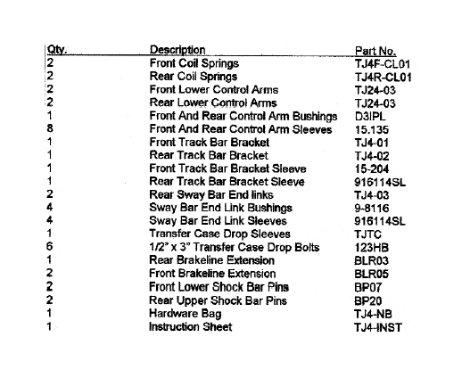
PARTS LIST:
Special Note: The Jeep TJ comes from the factory with a variety of options such as engine size, hard top or soft top. All of these options can and do effect the ride height of the vehicle. Other add on components such as winches, heavier bumper and tools boxes will also effect the lift height of the vehicle. The recommended tire size for this suspension system is 33" x 12.50" x 15"
Congratulations on your selection to purchase a Tuff Country Suspension System. We at Tuff Country are proud to offer a high quality product at the industries most competitive pricing. Thank you for your confidence in us, and our product.
Important Notes: Please read before beginning installation. OEM Manual should be used as a reference.
Check off parts list to be sure all parts are on hand. If any part is missing, you may call Tuff Country at: (800) 288-2190.
Read and understand all sections of instruction manual. Use locktite on all bolts associated with this installation.
TUFF COUNTRY SUSPENSION highly recommends a qualified and or certified mechanic to perform this installation.
WARNING
If you desire to return vehicle to stock make sure to save all stock components.
IMPORTANT CUSTOMER INFORMATION
This vehicle's reaction and handling characteristics may differ from standard cars and/or trucks. Modifications to improve and or enhance off road performance may raise the intended center of gravity. Extreme caution must be utilized when encountering driving conditions which may cause vehicle imbalance or loss of control. Drive Safely!, Avoid abrupt maneuvers, such as sudden sharp turns, which could cause a roll over, resulting in serious injury or death.
It is the customer's responsibility to make sure a re-torque is performed on all hardware associated with this suspension system after the first 100 miles of installation. It is also the customer's responsibility to do a complete re-torque after every 1000 miles or after every off road use.
After the original installation, Tuff Country also recommends having the alignment checked every 6 months to ensure proper tracking, proper wear on tires and front end components. Tuff Country takes no responsibility for abuse, improper installation, or improper suspension maintenance.
IMPORTANT NOTICE
DO NOT install a body lift in combination with a suspension system. If a body lift is used in conjunction with any Tuff Country Suspension product, your Tuff Country WARRANTY WILL BE VOID.
NOTICE
It is the responibilty of the customer or the mechanic to wear safety glasses at all times when working with air tools.
Product safety label must be installed inside the cab in plain view of all occupants.
Please Follow Instruction Carefully
Before installation begins, drive and check to make sure there are not any uncommon sounds and or frame damage. Also at this time measure from the center of the hub to the bottom of fender well and record:
Pre Installation Measurements:
Driver Side Front __________________________________________
Passenger Side Front ______________________________________
Driver Side Rear __________________________________________
Passenger Side Rear ______________________________________
At the end of the installation take the same measurements and compare to the pre installation measurements.
Post Installation Measurement:
Driver Side Front __________________________________________
Passenger Side Front ______________________________________
Driver Side Rear __________________________________________
Passenger Side Rear ______________________________________
Front End Installation:
1.To begin installation, block the rear tires of the vehicle so that the vehicle is stable and can't roll backwards. Safely lift the front of the vehicle and support the frame with jack stands. Place a jack stands on both the driver and the passenger side. Next remove the wheels and tires from both sides.
2. Working on the driver side, locate the top of the shock absorber stud and remove the nut, retainer washer and grommet. Repeat procedure on passenger side. Special Note: Some Jeep TJ's have a variation on the grommet sizes, save the stock grommets, they may need to be re-installed.
3. Using hydraulic floor jacks, support the front axle on the driver and passenger side. Next, remove the stock lower shock bolts and nuts and save for later re-installation. (stock shock absorbers can be discard). Longer shocks will be needed with this suspension system. (Shock not included).
4. On the driver side, disconnect the stock sway bar end links from the stock axle location and save hardware for later re-installation. Repeat procedure on passenger side. Next, remove the stock brake lines from inner frame rail and save hardware for later re-installation.
5. Double check to make sure that the hydraulic jacks are supporting the axle and remove the stock bolt that connects the stack track bar to the stock location on the passenger side axle. Save hardware for later re-installation.
6. Remove the passenger side bolt that connects the stock stabilizer to the stock location and save hardware, if so equipped.
7. On the driver side locate the stock lower control arm. On the front mounting bracket scribe a mark on the stock alignment cams and reinforcement bracket. This is done for a later installation reference. Repeat procedure on passenger side.
8. On the driver side, remove the stock lower control arm and discard. Save hardware for later re-installation. Repeat procedure on passenger side.
9. On the driver side, remove the stock coil clip and save hardware for later re-installation, if so equipped. Repeat procedure on passenger side.
10. Lower down on both hydraulic floor jacks at the same time. Lower jacks enough that the stock coil springs can be removed. On the driver side, remove the stock coil spring and discard. Repeat procedure on passenger side.
11. Locate the new front coil springs, on the driver side install the new coil spring into to stock location. Repeat procedure on passenger side.
12. On the driver side, re-install the stock coil spring clip with stock hardware, if so equipped. Repeat procedure on passenger side.
13. Raise up on the hydraulic floor jacks until the new coil springs seat properly. Note: Make sure the rubber spring isolator is flush with the upper stock frame brackets on each side.
14. Locate the (2) new front lower control arms, new poly bushings from poly bag label D3IPL and (4) lower control arm anti crush sleeves. Insert the new poly bushing into each end of the control arms. The bushing are a two piece bushing, so each arm should receive (4) bushings. Now press in the anti crush sleeves through the bushings on each end. Special Note: Use a lithium or moly base grease prior to inserting bushing into the new lower control arms. This will increase the life of the bushings as well as prevent squeaking.
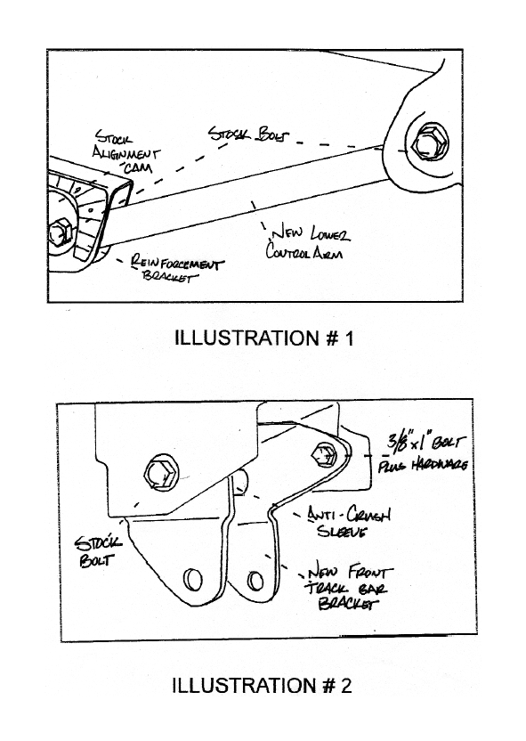
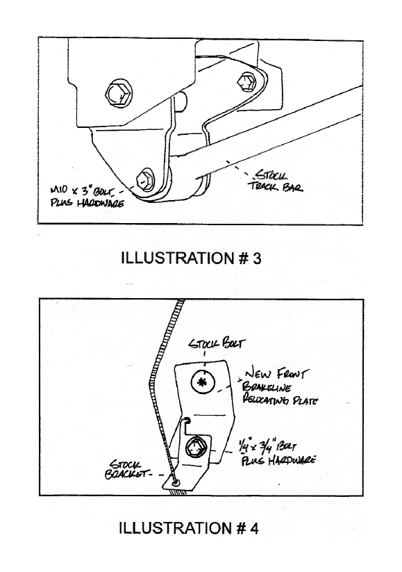
15. On the driver side, install the new lower control arm into the rear mount and secure using stock hardware. Do not fully tighten at this point. Insert the front of the lower control arm into the front bracket. Special Note: Slight prying of the stock control arm mounts may be needed to make installation easier. Also raising the axle to ride height and moving it slightly up and down will make for easier installation. Now re-install the stock cam bolt and nut. Refer to the reference mark that was make in step # 7 and re-bolt into the stock location.
Special Note: Torque both the front and rear mount to 80 ft. lbs. Repeat procedure on passenger side.
See Illustration # 1
16. Locate the new track bar relocating bracket, (1) lOmm x 3" bolt, (1) 10 mm Jock nut, (1) 3/8" x 1" bolt, (1) 318" unitorque nut, (4) 3/8" flat washers and (1) 15.204 track bar anti crush sleeve. Install new track bar relocation bracket into passenger side stock track bar location with the open end down. Install new spacer sleeve into the upper hole of new track bar bracket. Secure using stock hardware. Do not fully tighten at this point. Make sure that the newly installed track bar relocation bracket is level use the new bracket as a guide and drill a 3/8" hole into the back side of stock track bar bracket. Secure using new 3/8" hardware and torque to 32 ft lbs.
See Illustration # 2
17. Install the stock track bar into newly installed track bar bracket and secure using (1) 10 mm x bolt, (1) 10 mm lock nut and (2) 3/8" flat washers, Torque to 45 ft lbs. If you are not able to line up the hole in the stock track bar and the new track bar bracket, the weight of the vehicle may need to be on the ground, if this is the case perform this step after installation step # 21
See Illustration # 3
18. Locate (2) new front brakeline extensions, (2) 114" x 3/4" bolts, (2) 1/4" unitorque nuts and (4) 1/4" flat washers. On the driver side install new brakeline bracket to inner frame rail. Secure using stock hardware. Install stock brakeline brake to new brakeline bracket and secure using 1/4" hardware. Torque to 15 ft lbs. Repeat procedure on passenger side.
See Illustration # 4
19. Longer shock will be needed with this suspension kit. Tuff Country recommends a 23" fully extended hydraulic shock. In the poly bag with your instruction sheet locate the shock bar pins. Install the new bar pin into each shocks lower eyelet. Install the shock dust boot cover on both shocks. On the driver side, install the new shock into the lower stock location and secure using lower shock mounting hardware. Install the upper shock mount into the stock location and secure using new grommets and 3/8" nut. Special Note: Stock grommets may need to be re-installed if new grommets are to small.
20. Re-install the stock stabilizer into the stock location and secure using stock hardware.
21. Re-install the stock sway bar end links into stock location and secure using stock hardware Special Note: If the end links are not able to be reconnect the weight of the vehicle might have to be on the ground. Check and double check to make sure that all installation steps were performed properly and that all hardware is torqued to proper specifications. mount wheels and tire and safely lower vehicle to the ground.
if you were unable to line up the stock track bar and new track bar bracket from step # 17. Perform step # 17 at this time.
Front End Installation complete:
Rear End Installation:
22. Block the front tires of the vehicle so that the vehicle is stable and can't roll forward. Safely lift the rear of the vehicle and support the frame with jack stands. Place a jack stands on both the driver and the passenger side. Next remove the wheels and tires from both sides.
23. Position hydraulic floor jacks under both the driver and passenger side rear axle, Raise up on both floor jacks until contact is made on the axle.
24. On the driver side, remove the stock sway bar end link from the stock location and discard the stock end link. New end links are provided in this suspension system. Save stock hardware and repeat procedure on passenger side.
25. Remove both rear shock absorbers and discard. Save stock hardware for later re-installation. Longer shocks will be needed with suspension system. (Shock not included).
26. On the driver side, remove the stock bolt that connects the stock track bar to the stock location and save hardware for later re-installation. Special Note: Remove the stock plastic cover that overlaps the stock rear track bar bracket and discard.
27. On the driver side, remove the stock lower control arm and discard. Save hardware for later re-installation. Repeat procedure on passenger side.
28. On the driver side, remove the stock coil clip and save hardware for later re-installation, if so equipped. Repeat procedure on passenger side.
29. Lower down on both hydraulic floor jacks at the same time. Lower jacks enough that the stock coil springs can be removed. On the driver side, remove the stock coil spring and discard. Repeat procedure on passenger side.
30. Locate the new rear coil springs, on the driver side install the new coil spring into to stock location. Repeat procedure on passenger side.
31. On the driver side, re-install the stock coil spring clip with stock hardware, if so equipped. Repeat procedure on passenger side.
32, Raise up on the hydraulic floor jacks until the new coil springs seat properly into stock location. Note: Make sure the rubber spring isolator is flush with the upper stock frame brackets on each side.
33. Locate the (2) new rear lower control arms, new poly bushings from poly bag label D3IPL and (4) lower control arm anti crush sleeves Insert the new poly bushing into each end of the control arms. The bushing are a two piece bushing, so each arm should receive (4) bushings. Now press in the anti crush sleeves through the bushings on each end. Special Note: Use a lithium or moly base grease prior to inserting bushing into the new lower control arms. This will increase the life of the bushings as well as prevent squeaking.
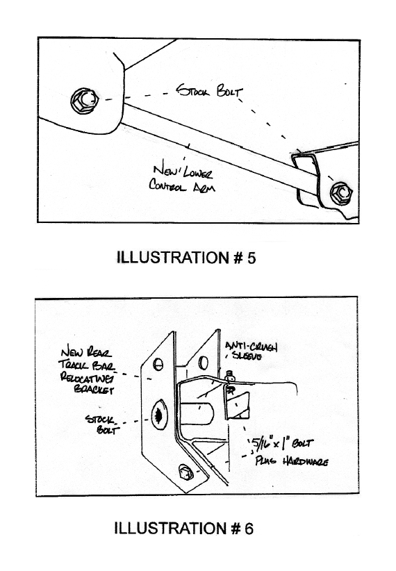
34. On the driver side, install the new lower control arm into the front mount and secure using stock hardware. Do not fully tighten at this point. Insert the rear of the lower control arm into the rear bracket. Special Note: Slight prying of the stock control arm mounts may be needed to make installation easier. Also raising the axle to ride height and moving it slightly up and down will make for easier installation. Secure using stock hardware. Note: Torque both the front and rear mount to 90 ft. lbs. Repeat procedure on passenger side.
See illustration # 5
35. Locate the new rear track bar bracket. (1) 12 mm x 3" bolt, (1) 12 mm lock nut, (2) 5/16' x 1" bolt, (2) 5/16" unitorque nuts, (4) 5/16" flat washers, (2) 7/16" flat washers and (1) rear track bar anti crush sleeve. Install the new rear track bar bracket over the stock track bar bracket and secure using stock hardware and new anti crush sleeve into the stock location. Torque to 75 ft lbs. Using the new bracket as a guide, drill a 5/16" hole in the bottom and the top of the stock track bar bracket. Secure using 5/16" x 1" bolt and hardware. Torque to 18 ft lbs.
See Illustration # 6
36. Install the stock track bar into newly installed track bar bracket and secure using (1) 12 mm x 3" bolt, (1) 12 mm lock nut and (2) 7/16" flat washers. Torque to 45 ft lbs. If you are not able to line up the hole in the stock track bar and the new track bar bracket, the weight of the vehicle may need to be on the ground, if this is the case perform this step after installation step # 38
See Illustration # 7
37. Locate (2) new rear sway bar end links, (4) sway bar end link bushings and (4) rear sway bar end link sleeves. Install new bushing and sleeves into each end of the new sway bar end links. Special Note: Use a lithium or moly base grease prior to inserting bushing into the new sway bar end links. This will increase the life of the bushings as well as prevent squeaking. On the driver side install the new sway bar end link into the stock location and secure using stock hardware. Torque to 85ft lbs. Repeat procedure on passenger side.
38. Longer shock will be needed with this suspension kit. Tuff Country recommends a 26" fully extended hydraulic shock. Install the shock dust boot cover on both shocks. In the poly bag with your instruction sheet locate the shock bar pins. Install the new bar pin into each shocks upper eyelet. On the driver side, install the new shock into the upper stock location and secure using upper shock mounting hardware. Install the lower shock mount into the stock location and secure using stock hardware.
39. Check and double check to make sure that all steps were performed properly. Re-install the tires and wheels and safely lower the vehicle to the ground.
If you were unable to line up the stock track bar and new track bar bracket from step # 36. Perform step # 36 at this time.
Rear End Installation Complete:
TRANSFER CASE LOWERING KIT
Before beginning these steps: Make sure vehicle is on a flat and level surface, block the front and rear tires and place transmission in neutral.
40. Place a jack stand under the transfer case crossmember and remove the six stock bolts that secures the stock transfer case skid plate to the frame. (Three on each side of the skid plate). Stock bolts may be discarded. Ease down on jack so that the skid plate lowers about 2".
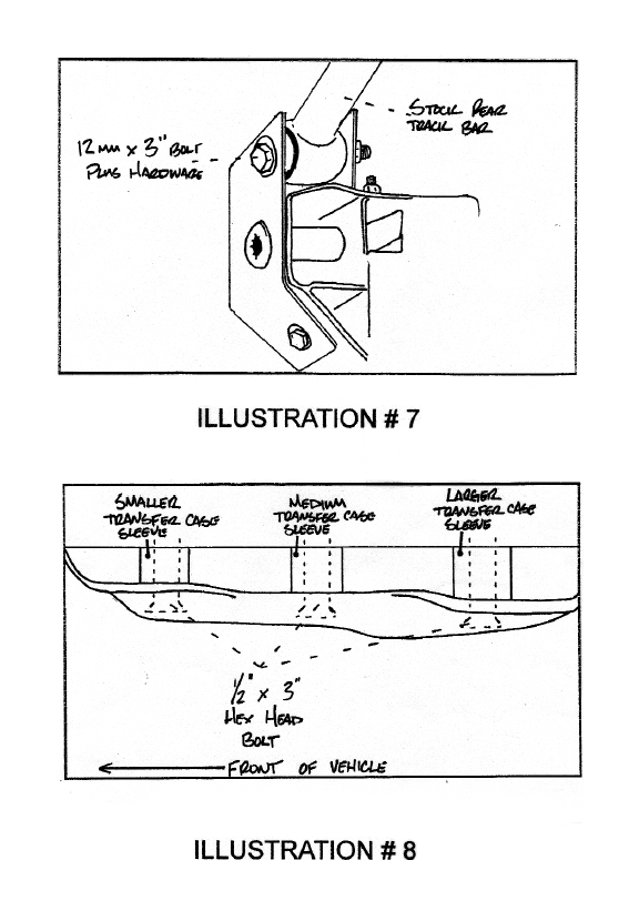
26. Locate (6) transfer case sleeves (Three different sizes) and (6) 1/2" x 3" hex head bolts. Install the new transfer case sleeves between the transfer case cross member and frame. Three per side. Special Note: There are three different size sleeves. The Longer sleeves will go towards the rear of the vehicle, the middle sleeves will go in the middle location and the smaller sleeves will go towards the front of the vehicle. Secure transfer case cross member to frame using the 1/2" x 3" hex head bolts and torque to 85 ft lbs. Make sure to use lock tight on the new transfer case bolts and Tuff Country highly recommended that a air ratchet is used. If a air gun is used the new bolts may strip.
See Illustration 8
Transfer Case Lowering Kit Installation Complete:
Check and double check to make sure all steps were performed properly and take directly to an alignment center for proper alignment.
Congratulations Installation Complete