 FREE 1 to 3-Day Delivery on Orders $149+ Details

How to Install Tuff Country 2 in. Suspension Lift Kit w/ Shocks (97-06 Wrangler TJ) on your Jeep Wrangler
Front End Installation:
1. To begin installation, block the rear tires of the vehicle so that the vehicle is stable and can’t roll backwards. Safely life the front of the vehicle and support the frame with jack stands. Place a jack stand on both the driver and passenger side. Next remove the wheels and tires from both sides.
2. Place a hydraulic floor jack on both the driver and passenger side of the front differential. Raise up on both hydraulic jack stands at the same time until they make contact with the front differential.
3. Working on the driver side, remove the stock front sway bar end link from the stock front axle and save hardware for later re-installation. Repeat procedure on passenger side.
4. Working on the driver side, remove the stock front shock from the stock location and save mounting hardware for later re-installation. Longer shocks will be needed, the stock shocks may be discarded. Repeat procedure on passenger side.
5. Working on the passenger side, remove the stock track bar from the stock axle location and save hardware for later re-installation.
6. Working on the driver side, remove the stock lower control arm from the stock frame location and save hardware for later re-installation. Repeat procedure on passenger side.
7. Carefully lower down on both hydraulic floor jacks at the same time approximately 3”. This will allow enough room for the stock coil springs to be removed. Special Note: Make sure that the stock brake lines do not over extend.
8. Working on the driver side, remove the stock coil spring retaining clip from the stock location and save clip and hardware for later re-installation. (If so equipped) Repeat procedure on passenger side.
9. Working on the driver side, remove the stock coil spring and set aside for later re-installation. Repeat procedure on passenger side.
10. Working on the driver side, remove the stock front bump stop and discard. Repeat procedure on passenger side.
11. Working on the driver side, remove the stock front bump stop cup and save hardware for later re-installation. Repeat procedure on passenger side.
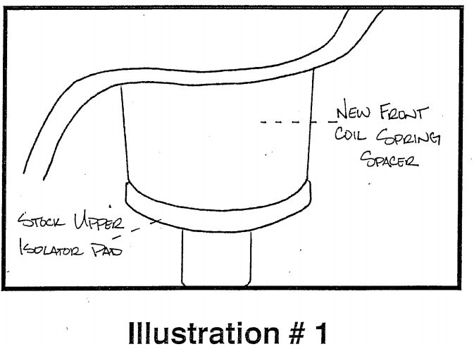
12. Locate (2) front coil spring spacers. Working on the driver side, install the front coil spring spacer into the stock front coil spring pocket. Special Note: To make installation easier, use a lithium or moly base grease to help the new spacer slide up into the stock pocket. Also make sure that stock upper isolator pad is installed on the bottom of the coil spring spacer. Repeat procedure on passenger side.
See Illustration #1
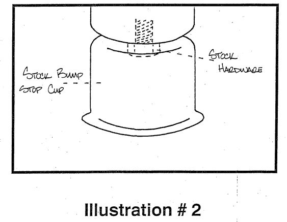
13. Working on the driver side, re-install the stock bump stop cup using the stock hardware that was removed in step #11. Repeat procedure on passenger side.
See Illustration #2.
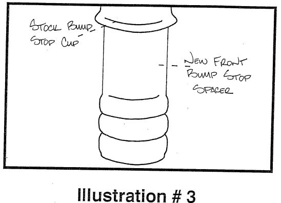
14. Locate (2) new front bump stop spacers. Working on the driver side, install the front bump stop spacer into the stock bump stop cup. Special Note: To make installation easier, use a lithium or moly base grease to help the new bump stop spacer slide up into the stock pocket. Repeat procedure on passenger side.
See Illustration #3.
15. Working on the driver side, re-install the stock coil spring that was removed in step #8. (If so equipped) Repeat procedure on passenger side.
16. Working on the driver side, re-install the stock coil spring retaining clip that was removed in step #8. (If so equipped) Repeat procedure on passenger side.
17. On the driver side, re-install the stock lower control into the stock frame location and secure using the stock hardware that was removed in step #6. Torque to 85 ft. lbs. Special note: Slight prying of the stock lower control arm mounts may be needed to make installation easier. Also raising the axle to ride height and moving it slightly up and down will make for easier installation. Repeat procedure on passenger side.
18. Working on the driver side, re-install the stock front track bar into the stock front track bar bracket and secure using the stock hardware that was removed from step #5. Torque to 30 ft. lbs. Special Note: If you are not able to line up the hole in the stock track bar and the stock track bar bracket, the weight of the vehicle may need to be on the ground. If this is the case perform this step, once the weight of the vehicle is on the ground.
19. Longer shocks will be needed with this suspension system. Tuff Country EZ-Ride Suspension recommends using a 20” fully extended hydraulic shock.
20. Working on the driver side, install the new shock into the stock location and secure using the stock hardware that was removed from step #4. Repeat procedure on the passenger side.
21. Working on the driver side, re-install the stock sway bar end link to the stock axle location and secure using the stock hardware that was removed from step #3. Repeat procedure on passenger side. Special Note: If you are not able to re-install the stock sway bar end link to the stock sway bar, the weight of the vehicle may need to be on the ground. If this is the case perform this step, once the weight of the vehicle is on the ground.
22. Carefully remove both hydraulic floor jacks. Install the tires and wheels, and safely lower the vehicle to the ground.
23. If you were not able to perform step #18 & #21, perform these steps at this point.
24. Check and double check to make sure that all steps associated with with front end suspension system were performed properly.
Front End Installation Complete!
Rear End Installation:
25. To begin installation, block the front tires of the vehicle so that the vehicle is stable and can’t roll forward. Safely lift the rear of the vehicle and support the frame with jack stands. Place a jack stand on both the driver and passenger side. Next remove the wheels and tires from both sides.
26. Place a hydraulic floor jack on both the driver and passenger side of the rear differential. Raise up on both hydraulic jack stands at the same time until they make contact with the front differential.
27. Working on the driver side, remove the stock rear sway bar end link from the stock sway bar location and save hardware for later re-installation. Repeat procedure on passenger side.
28. Working on the driver side, remove the stock rear shock from the stock location and save mounting hardware for later re-installation. Longer shocks will be needed, and stock shocks may be discarded. Repeat procedure on passenger side.
29. Working on the passenger side, remove the stock track bar from the stock frame location and save hardware for later re-installation.
30. Working on the driver side, remove the stock lower control arm from the stock frame location and save hardware for later re-installation. Repeat procedure on passenger side.
31. Carefully lower down on both hydraulic floor jacks at the same time approximately 3”. This will allow enough room for the stock coil springs to be removed. Special Note: make sure that the stock brake lines do not overextend.
32. Working on the driver side, remove the stock coil spring retaining clip from the stock location and save clip and hardware for later re-installation. (If so equipped). Repeat procedure on passenger side.
33. Working on the drive side, remove the stock coil spring and set aside for later re-installation. Repeat procedure on passenger side.
34. Working on the driver side, remove the stock rear bump stop and discard. Repeat procedure on passenger side.
35. Working on the driver side, remove the stock rear bump stop cup and save hardware for later re-installation. Repeat process on passenger side.
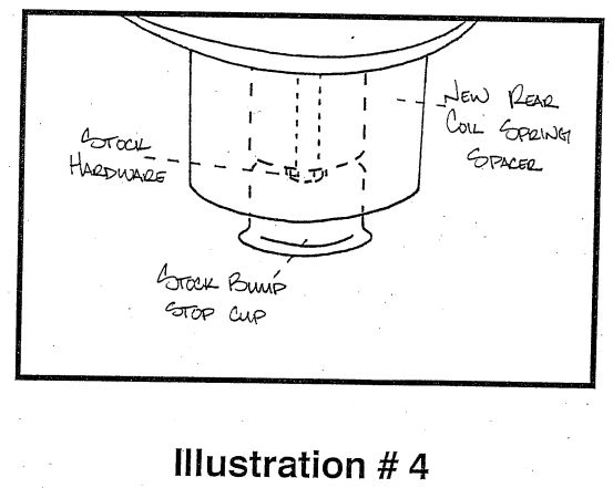
36. Locate (2) new rear coil spring spacers. Carefully press in the stock rear bump stop cup that was removed from step #35. Working on the driver side, install the rear coil spring spacer into the upper stock coil spring pocket using stock hardware for the stock bump stop cup. Repeat procedure on passenger side.
See Illustration #4.
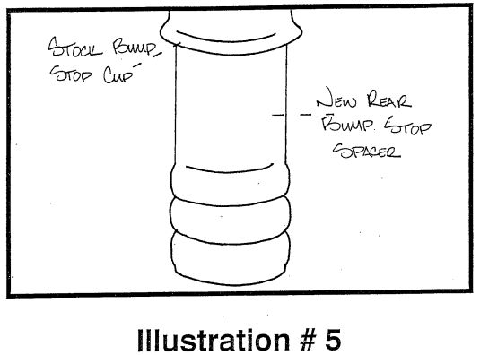
37. Locate (2) new rear bump stop spacers. Working on the driver side, install the rear bump stop spacer into the stock bump stop cup. Special Note: To make installation easier, use a lithium or moly base grease to help the new bump stop spacer slide up into the stock pocket. Repeat procedure on passenger side.
See Illustration #5.
38. Working on the driver side, re-install the stock coil spring that was removed in step #33. Repeat procedure on passenger side.
39. Working on the driver side, re-install the stock coil spring retaining clip that was removed in step #32. (If so equipped) Repeat procedure on passenger side.
40. On the driver side, re-install the stock lower control into the stock frame location and secure using the stock hardware that was removed in step #30. Torque to 85. ft. lbs. Special Note: Slight prying of the stock lower control arm mounts may be needed to make installation easier. Also raising the axle to ride height and moving it slightly up and down will make for easier installation. Repeat procedure on passenger side.
41. Working on the driver side, re-install the stock rear track bar into the stock frame rear track bar bracket and secure using the stock hardware that was removed from step #29. Torque to 30 ft. lbs. Special Note: If you are not able to line up the hole in the stock track bar and the stock track bar bracket, the weight of the vehicle may need to be on the ground. If this is the case perform this step once the weight of the vehicle is on the ground.
42. Longer shocks will be needed with this suspension system. Tuff Country EZ-Ride Suspension recommends using a 23” fully extended hydraulic shock.
43. Working on the driver side, install the new shock into the stock location and secure using the stock hardware that was removed from step #28. Repeat procedure on the passenger side.
44. Working on the driver side, re-install the stock sway bar end link to the stock location and secure using the stock hardware that was removed from step #27. Repeat procedure on passenger side. Special Note: If you are not able to re-install the stock sway bar end link to the stock sway bar, the weight of the vehicle may need to be on the ground. If this is the case, perform this step once the weight of the vehicle is on the ground.
45. Carefully remove both hydraulic floor jacks. Install the tires and wheels and safely lower the vehicle to the ground.
46. If you were not able to perform step #41 & #44, perform these steps at this point.
47. Check and double check to make sure that all steps associated with the rear end suspension system were properly performed.
Rear End Installation Complete!
Transfer Case Lower Kit
Before beginning these steps, make sure the vehicle is on a flat level surface, block the front and rear tires and place the transmission in neutral.
48. Place a hydraulic jack stand under the transfer case cross member and raise up until the hydraulic jack makes contact with the transfer case cross member.
49. Working on the driver side, remove the (3) stock bolts that hold the transfer case cross member to the frame. New bolts will be used, the stock bolts may be discarded. Repeat procedure on passenger side.
50. Carefully lower down on the hydraulic floor jack so that the transfer case cross member lowers about 2”.
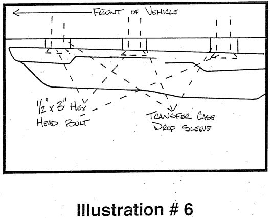
51. Locate (6) transfer case sleeves, (three different sizes) and (6) 1/2” x 3” hex head bolts. Working on the driver side, install the new transfer case drop sleeves between the transfer case cross member and the frame, (3) per side. Special Note: There are three different sizes of sleeves, the longer sleeve will go towards the rear of the vehicle, the middle size sleeve will go in the middle location nad the smaller sleeve will go towards the front of the vehicle. Securely the transfer case cross member to the frame using the new 1/2” by 3” hex head bolts and torque to 85 ft. lbs. Special Note: Make sure to use locktite on the new transfer case bolts. Also Tuff Country does not recommend using an air gun on these bolts, if an air gun is used the new bolts may strip. Repeat procedure on passenger side.
See Illustration #6.
52. Safely remove the hydraulic floor jack from under the vehicle.
Transfer Case Lower Kit Installation Complete!

