 FREE 1 to 3-Day Delivery on Orders $149+ Details

How to Install Teraflex Elite LCG Long Arm Upgrade Kit-Arms and Brackets on your 1997-2006 Wrangler
Read this first:
Installation of this kit requires removal of the factory control arm mounts from the frame. The preferred removal method is a combination of zip wheel and plasma cutter, with some cleanup grinding required. The new brackets must be welded in place as part of the installation of the kit. If you are not properly equipped to safely do this level of fabrication and welding, please contact TeraFlex for the name of a qualified installer in your area. Plan to spend 20 or more hours for installation.
With proper patience and care it is possible to leave the fuel tank in place during this installation. The photos accompanying our installation guide show just how to cut and remove the rear brackets without damaging the fuel tank.
Kit includes:
Front lower control arms - Qty 2
Front upper control arms - Qty 2
Rear upper control arms - Qty 2
Left Rear lower control arm - Qty 1
Right Rear lower control arm - Qty 1
Hardware kit
Frame brackets - 2 Front, 2 Rear
Installation:
The steps in this installation guide cover removal of the factory control arm brackets and installation of the new TeraFlex JK long arms brackets. Other lift and shock installation steps are covered in the installation guide that comes with each basic lift size and configuration.
1. Remove all of the factory control arms
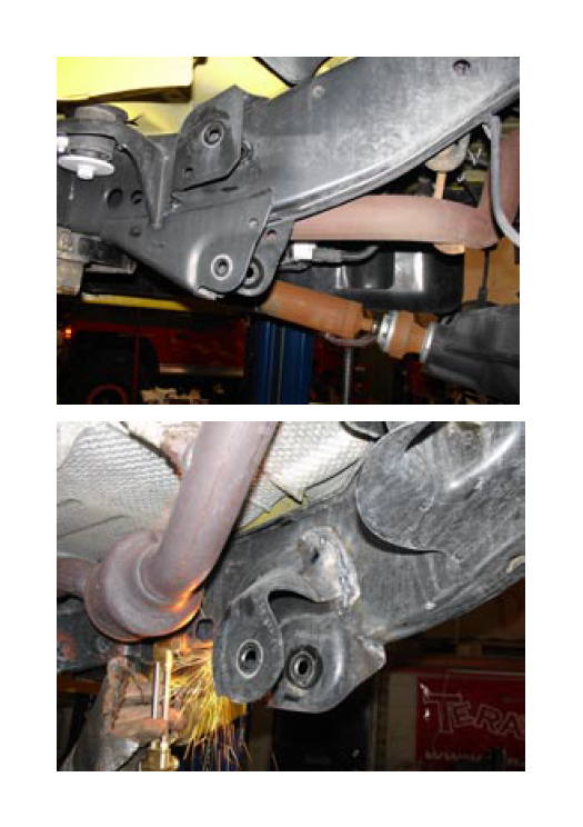
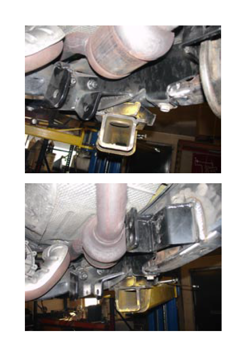
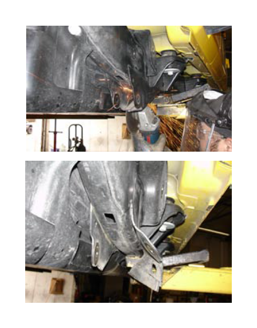
2. Use a plasma cutter, oxy/acetylene torch or zip cutoff wheel to remove just the bracket. Be very careful to avoid undercutting into the frame. Use the following photos to determine where to cut. In the case of the rear lower control arm bracket, it is easier to cut the bracket into sections and then remove each section to minimize heat buildup near the fuel tank.
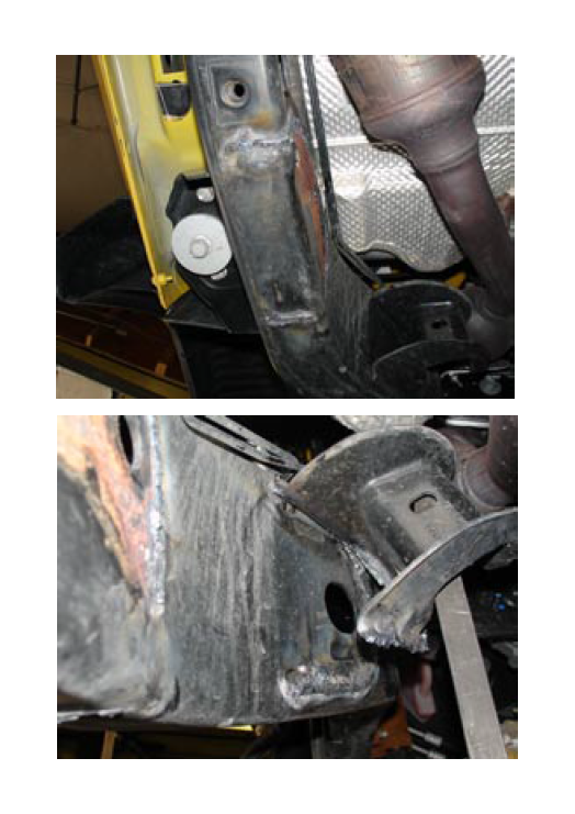
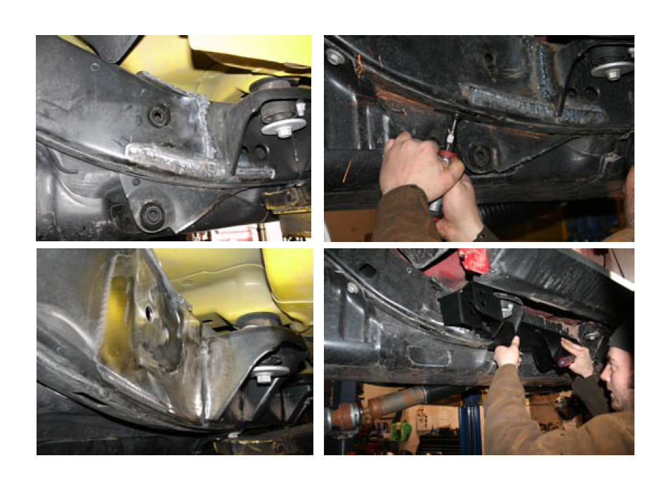
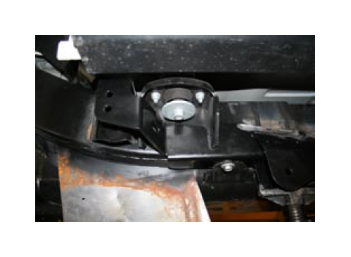
3. Remove both front upper and lower brackets and grind the remaining weld smooth with the frame in preparation for installing the new combination front bracket. The new front bracket mounts to the cross member bolts, locates to an existing hole in the frame with a single bolt up through the bottom of the frame (some models may not have threads in this frame hole). Push the new bracket up tight against the frame before welding in place.
4. Fully weld the front long arm brackets to the frame, then paint the welds to avoid rust. Repaint any bare metal exposed areas on the frame from the cutting and grinding process.
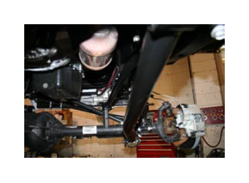
5. The front lower arms are installed with the rubber bushing at the frame end and the angled modular urethane joint at the axle end. The front upper arms have the open end at the axle mount as shown in the photo. Position grease zerks for access and where they will be most protected from rocks or other damage.
NOTE: The following photos show cutting the right rear lower frame bracket in half and then spreading it to be able to cut it off in sections.
Be very careful to avoid damage to the fuel tank.
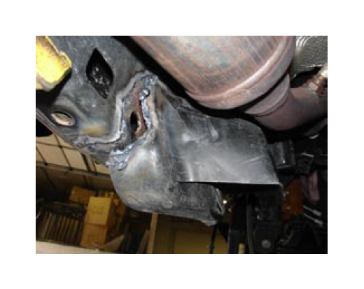
Use a cutoff zip wheel to trim the inner bracket even with the bottom of the frame. Grind the paint off where the new bracket will sit to ensure a good weld.
6. Use a heat shield as shown in the photo below to protect the fuel tank during final grinding and installation and welding of the new right rear long arm bracket.
Additional information:
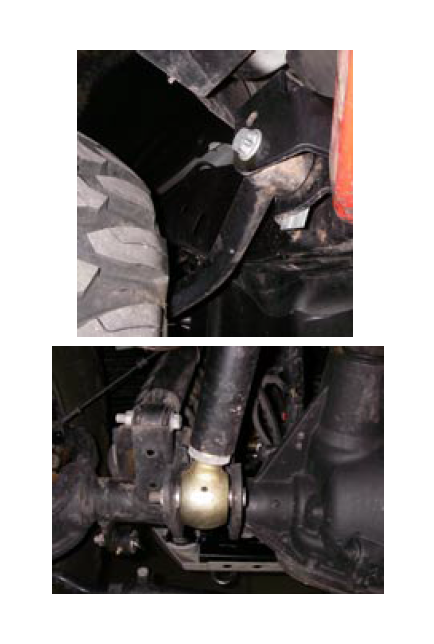
On the front lower arms the forged modular end that goes on the axle bracket is angled slightly so the joint is centered or “neutral” when the vehicle is sitting centered and level on the gournd. The rear upper arms are angled away from the tire to provide maximum clearance for larger tires. See photos to the right.
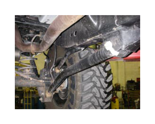
Front and rear upper arms can be installed in two locations on the new long arm bracket. This is for tuning of “anti-squat”. On most installations you should use the lower of the two holes for both the front and the rear upper control arms.
Suggested alignment information:
For initial settings on control arm length, suggested settings only, I will tell you what we use at our installation center. Final adjustments need to be made on the alignment rack. The following dimensions are what we use on a 4 door JK with 4 inch lift. These settings will be very close for a 2 door as well. Each vehicle will vary.
Front adjustable track bar - 33 1/8 inches
Rear adjustable track bar - 40 1/8 inches
Front upper control arms - 27 3/4 inches
Driver side front lower control arm - 33 9/16 inches
Passenger side front lower control arm - 33 11/16 inches
Rear upper control arms - 19 1/2 inches
Rear lower control arms - 35 1/8 inches
The different caster from left to right on the front works well on the highway crown we have in Utah to keep the vehicle from drifting to the side. You may find a slight change is required where you live.
All other standard TeraFlex terms and conditions apply to the long arm upgrade kit.
PRODUCTMAINTENANCE INFORMATION:It is the buyer’s responsibility to have all suspension, drivetrain, steering, and other components checked for proper tightness and torque after the first 100 miles and every 3,000 miles after that.
NOTICE TO INSTALLER: The enclosed “Warning to Driver” sticker must be installed in the vehicle in driver’s view. This sticker is to act as a constant safety reminder when operating the vehicle. It is your responsibility as the equipment installer to install the provided sticker and to forward the product instructions to the vehicle’s owner for review. If a “Warning to Driver” sticker or product installation guide were not included in the kit, FREE replacement stickers and instructions are available by request. It is the installer’s duty to ensure a safe and controllable vehicle after the modifications have been performed.
WARNING: Neither the seller nor the manufacturer will be liable for any loss, damage, or injury directly or indirectly arising from the use of or inability to determine the use of these products. Before using, the user shall determine the suitability of the products for its intended use, and the user shall assume all responsibility and risk in connection therewith.
WARNING TO DRIVER: This vehicle has been modified to enhance off road performance and has unique handling characteristics. Because of the higher center of gravity and larger tires, this vehicle handles and reacts differently than many passenger cars, both on and off road. You must drive it safely! Extreme care should be taken to prevent vehicle rollover or loss of control, which can result in serious injury or death. Avoid sudden sharp turns or abrupt maneuvers. Generally, braking performance and capabilities are decreased when significantly larger/heavier tires are used, especially when used in combination with transfer case low-range reduction kits. Take this into consideration while driving. Do not add, alter or fabricate any factory or aftermarket parts to increase vehicle height over the intended height of the Tera Manufacturing product purchased. Mixing component brand is not recommended. Tera Manufacturing will not be responsible for any altered product or any improper installation or use of our products. We will be happy to answer any questions concerning the design, function, and correct use of our products. It is ultimately the buyer’s responsibility to have all bolts/nuts checked for tightness after the first 100 miles and then every 3,000 miles. Wheel alignment, steering system, suspension and drive line systems must be inspected by a qualified professional mechanic at least every 3,000 miles.
TERAFLEX PRODUCT WARRANTY:
Tera Manufacturing warrants TeraFlex Suspension products to the original retail purchaser to be free of defects in material and workmanship for as long as the original purchaser owns the vehicle on which products were originally installed.
Failure to complete regular maintenance (grease every 3,000 miles) on TeraFlex FlexArms will void this warranty. All other conditions of the standard Tera Mfg. product warranty apply.
All TeraLow products are covered by Tera’s two (2) year warranty to be free of defects in material and workmanship for two year’s from date purchased.
Tera axles are covered by a 12-month warranty to be free of defects in materials and workmanship.
The TeraFlex T-Locker is covered by a three (3) year warranty to be free of defects in materials and workmanship. This warranty does not cover or include product finish, improperly installed or applied products, improperly maintained products, products or components used for racing or competition or damage due to abuse or neglect, products that fail due to the use of larger tire and wheel combinations. All returns must be accompanied by an original invoice. It is the customer’s responsibility to remove the product from the vehicle. Shipping charges are the responsibility of the customer. Tera Manufacturing will pay the return freight.
This warranty is for the replacement or repair of defective TeraFlex products only and does not include freight charges, labor charges for removal of or installation of TeraFlex or related products or components, costs incurred due to down time of the vehicle, or lost profits due to vehicle down time.
A returned goods authorization number (RGA#) must accompany any returned products. For more information please contact a TeraFlex customer service representative.
