 FREE 1 to 3-Day Delivery on Orders $149+ Details

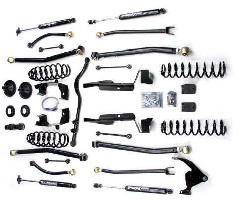
How to Install Teraflex 3 in. Lift Kit w/o Shocks on your Wrangler
Tools Required
- 6mm Allen Wrench
- 18mm Box Wrench
- 18mm Socket
- 19mm End Wrench
- Rachet
- Thread Locking Compound

Shop Parts in this Guide
Contents:
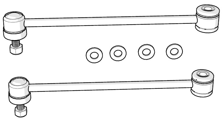
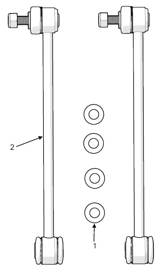
Rear Sway Bar Link Instructions
Spring Instructions
Bumpstop Instructions
Rear Track Bar Bracket Instructions
Extended Brake Line Instructions
Quick Disconnect Links Instructions
Spring Spacer Instructions
Rear Lower Spring Retainer Instructions
Rear Brake Line Extension Bracket Instructions
This packet may not include all necessary instruction sets for your lift kit. Check every received box for additional instruction sets.
Important Notes:
Prior to beginning this or any installation read these instructions to familiarize yourself with the required steps and evaluate if you are experienced and capable to personally perform these modifications. A factory service manual should be used in conjunction with these installation instructions.
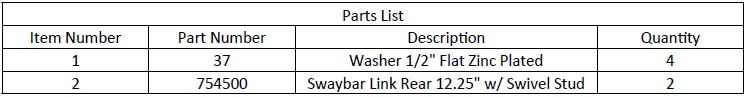
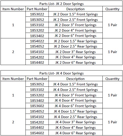
Refer to the parts list to ensure that all necessary components and hardware has been included. If any parts are missing please contact your local TeraFlex dealer for assistance.
1. Park the vehicle on a level surface and chock the front tires. Break the rear lug nuts loose with the vehicle on the ground but do not remove the nuts completely. Jack the rear of the vehicle off the ground and lower it onto jack stands. Remove the wheels.
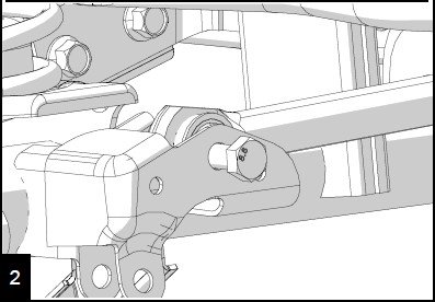
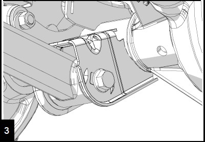
2. Using the 18mm socket and wrench, remove the bolt holding the factory link to the axle bracket.
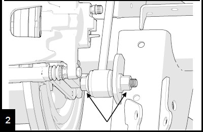
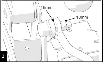
Using a 19mm wrench to hold the stud from turning and an 18mm to remove the nut, remove the link form the swaybar. Repeat steps 2 and 3 on other side.
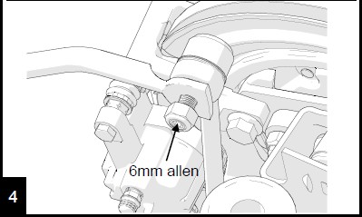
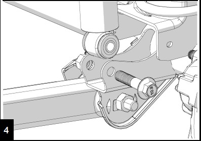
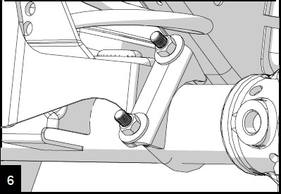
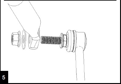
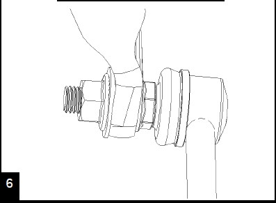
With both factory links removed, install the swivel end of the link into the swaybar from the outside. Install the new lock nut using the 19mm end wrench and the 6mm allen wrench. Torque to 66 ft-lbs
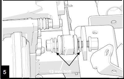
5. Using the 18mm install the factory hardware and two provid-ed washers on the lower end of the link. Place the washers on either side of the bushing. Torque to 75 ft-lbs.
6. Replace the wheels, torque to 110 ft-lbs. Raise off the jack stands, lower to the ground and remove the chocks.
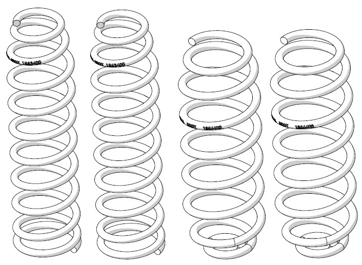
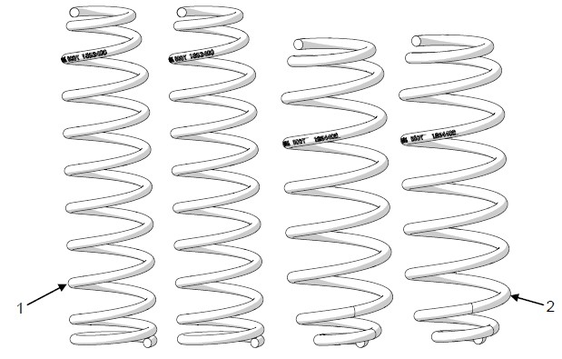
JK Spring Removal and Installation
Important Notes:
Prior to beginning this or any installation read these instructions to familiarize yourself with the required steps and evaluate if you are experienced and capable to personally perform these modifications. A factory service manual should be used in conjunction with these installation instructions.
This product will change the highway handling characteristics of your vehicle, exercise caution.
Refer to the parts list to ensure that all necessary components and hardware has been included. If any parts are missing please contact your local TeraFlex dealer for assistance.
FRONT REMOVAL
1. Refer to the factory service manual for lift locations. Raise and support the vehicle. Remove the tires and wheels and support the axle with a jack or jack stands.
2. Remove the track bar at the axle with a 21mm. The nut is a flag nut. (See 999208 Front Track Bar/Removal)
Loosen all front control arm bolts with a 21mm. DO NOT REMOVE ARMS OR BOLTS.
Remove the shocks at the axle with an 18mm wrench and socket. (See 999207 Shocks/Front/Removal)
Remove the sway bar links with an 18mm wrench and socket at the axle. If you are replacing the links, remove completely. (See 999027 Front Quick Disconnect/Removal)
Lower the jack until the spring is free. Remove the coil spring. Be sure to watch the ABS, brake lines and breathers that they are not over stretched..
FRONT INSTALLATION
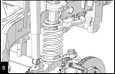
Install both coil springs, drivers side first followed by the passenger side. Rotate the spring until they are fully seated.
Raise the jack high enough to install the shocks. Torque to 56 ft-lbs (76 Nm). (See 999207 Shocks/Front/Installation)
Reinstall the sway bar links or install new links if supplied. Torque top and bottom to 75 ft-lbs. (See 999027 JK Quick Disconnect Links/Installation)
Reinstall the front track bar once the vehicle is sitting on the ground. Torque to 125 ft-lbs. (See 999208 Front Track Bar/ Installation)
Reinstall wheels and tires. Torque lug nuts to 95-115 ft-lbs. Once the vehicle is on the ground, torque upper control arm bolts to 75 ft-lbs and all lowers to 125 ft-lbs.
REAR REMOVAL
12. Refer to the factory service manual for lift locations. Raise and support the vehicle. Remove the tires and wheels and support the axle with a jack or jack stands.
13. Remove the rear track bar at the axle with a 21mm. The nut is a flag nut. (See 999043 Rear Track Bar/Removal)
With a 21mm loosen all rear control arm bolts. DO NOT REMOVE ARMS OR BOLTS.
Remove the shock at the axle with an 18mm. (See 999207 Shocks/Rear/Removal)
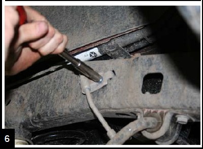
Remove the clips that secure the ABS wiring harness to the upper control arm mount.
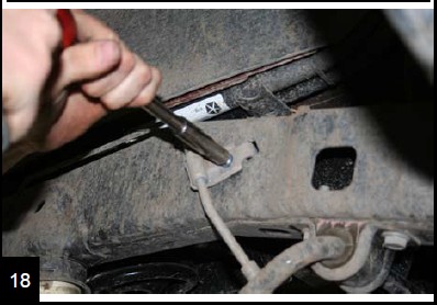
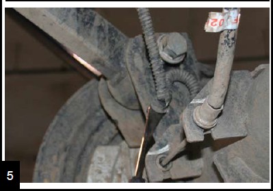
Remove the parking brake cable bracket from the underside of the body with a 10mm deep socket and discard.
Remove the brake line mount from the frame with a 10mm.
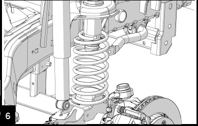
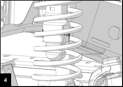
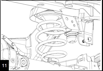
Carefully lower the axle enough to remove the spring. Be sure to watch the ABS, brake lines and breather tubes for overextension. Remove the old spring.
REAR INSTALLATION
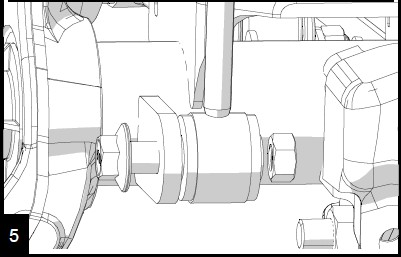
Install the new springs. Make sure to reuse the factory spring isolator.
Raise the axle high enough to reinstall the lower shock bolts. Torque to 56 ft-lbs. (See 999207 Shocks/Rear/Installation) Using a drop bracket if necessary, reinstall the brake line mount to frame. Torque to 16 ft-lbs.
Reinstall wheels and tires, torque to 95-115 ft-lbs. Lower to the ground. Torque all upper control arm bolts to 75 ft-lbs and all lower control arms to 125 ft-lbs.
23. Reinstall the rear track bar at the axle. Have someone push on the body to help align the bolt holes. Torque to 125 ft-lbs. (See 999043 Rear Track Bar/Installation) Recheck every bolt for torque . Re-torque all bolts after 100 miles.
24. To straighten the steering wheel, loosen the adjuster sleeve on the drag link with a 15mm. Make a mark across the sleeve and threads to indicate the original position. Looking from the drivers side, rotate the adjuster sleeve counter clockwise 3/4 of a turn. This should be pretty close. Every vehicle is different, test drive yours and adjust as needed. Torque the pinch clamp bolts to 45 ft-lbs.
Important Notes:
Prior to beginning this or any installation read these instructions to familiarize yourself with the required steps and evaluate if you are experienced and capable to personally perform these modifications. A factory service manual should be used in conjunction with these installation instructions.
Refer to the parts list to ensure that all necessary components and hardware has been included. If any parts are missing please contact your local TeraFlex dealer for assistance.
INSTALLATION
1. Refer to the factory service manual for lift locations. Raise and support the vehicle. Remove the tires and wheels and support the axle with a jack or jack stands.
2. Remove the shocks from the axle using a 13mm. Remove the ABS lines at the frame if equipped.
Remove the shocks at the axle with an 18mm. (See Shocks/ Front Removal 999207)
Disconnect the swaybar links front the axle with an 18mm. (See 999027 Quick Disconnect Links/Removal)
Lower the axle and remove the springs. (See Springs/Front Removal 999206) Upper bumpstop extensions installation see page 5 now.
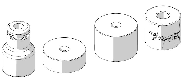
Locate the center of the spring pad and drill a 5/16” hole for standard pad installation. For speedbump pads, drill a 3/8” hole.
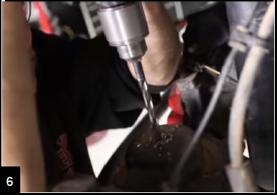
Use the standard bumpstop as a guide and thread the self tapping bolt into the hole. After threads are cut, remove the bolt and bumpstop.
Reinstall the springs and spacer together. Install the pad mounting bolt and tighten.
For Speedbump applications, install the bolt through the bumpstop with the nut below the spring pad.
Reinstall the shocks. (See 999207 Shocks/Front/Installation) Torque lower bolt to 56 ft-lbs.
Reconnect the swaybar links to the axle. Torque to 75 ft-lbs.
Reinstall the tires, remove supports and lower to the ground. Reinstall the front trackbar. (See Front Trackbar/Installation)
UPPER INSTALLATION
1. Park the vehicle on a level surface and set the parking brake. Raise the vehicle and support the frame to allow axle droop. Support the axle with a hydraulic jack. Remove the wheels and tires.
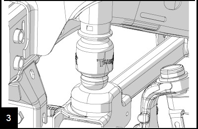
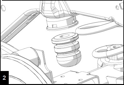
2. Perform steps 2-5 of the lower instructions. Then remove the factory bumpstop from the jounce tube by working it back and forth while twisting and pulling to the side.
Reinstall the bumpstop by aligning the bumpstop, extension, and jounce tube. Use the hydraulic jack and raise the axle until they are seated together. A grease coating will help.
Reinstall the spring and perform steps 10-12 of the lower instructions.
Important Notes:
Prior to beginning this or any installation read these instructions to familiarize yourself with the required steps and evaluate if you are experienced and capable to personally perform these modifications. A factory service manual should be used in conjunction with these installation instructions.
Refer to the parts list to ensure that all necessary components and hardware has been included. If any parts are missing please contact your local TeraFlex dealer for assistance.
UPPER INSTALLATION
1. Refer to the factory service manual for lift locations. Raise and support the vehicle. Remove the tires and wheels and support the axle with a jack or jack stands.
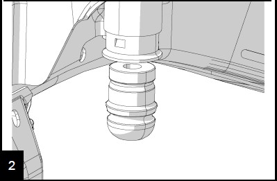
2. Remove the factory bumpstop from the cup on the frame by working it back and forth while twisting a puling to the side.
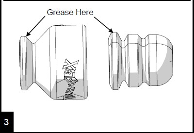
Apply grease to the bumpstop and the extension. Or just the strike pad.
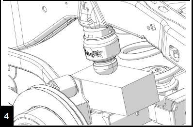
Align the bumpstop, extension and frame cup. Place a block between the frame and the axle bump pad. Raise the axle with a jack until the bumpstop and extension seat.
LOWER INSTALLATION
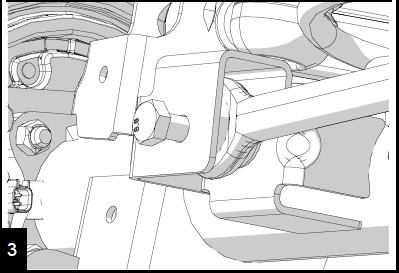
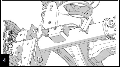
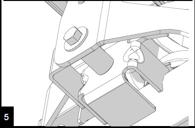
5. Park the vehicle on a level surface and set the parking brake. This installation can be done with the vehicle on the ground. Installation is the same for the Speedbump lower strike pad.
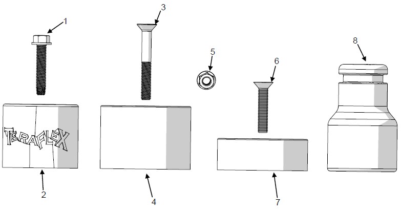
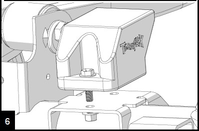
6. Align the extension on the factory pad with the “shelf” towards the front of the vehicle. Install the provided bolts with washers into the two holes. Torque to 25 ft-lbs.
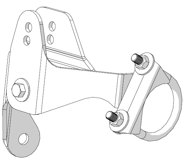
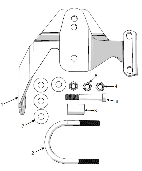
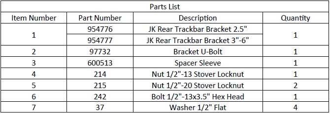
JK Rear Axle Track Bar Bracket
Important Notes:
Prior to beginning this or any installation read these instructions to familiarize yourself with the required steps and evaluate if you are experienced and capable to personally perform these modifications. A factory service manual should be used in conjunction with these installation instructions.
Refer to the parts list to ensure that all necessary components and hardware has been included. If any parts are missing please contact your local TeraFlex dealer for assistance.
REMOVAL
1. Properly raise and support the vehicle. See the factory service manual for proper support locations. Remove the left tire.
2. Remove the left lower control arm bolt at the axle end with a 21mm.
Remove the trackbar from the axle bracket with a 21mm. The nut is a flag nut.
INSTALLATION
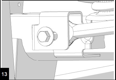
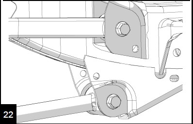
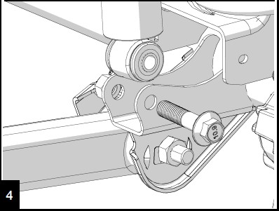
Position the TeraFlex bracket so it installs over the factory bracket and lines up with the lower control arm bolt. Reinstall the control arm bolt finger tight.
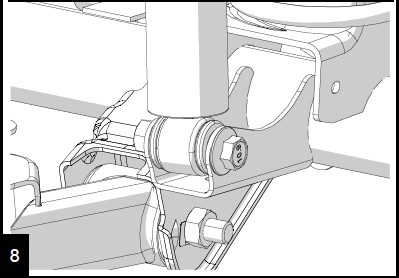
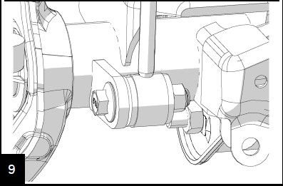
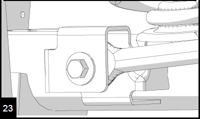
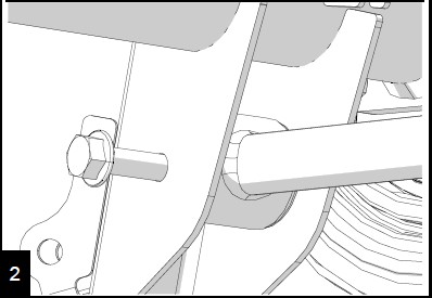
Use the provided sleeve as a spacer and install the 1/2”x3.5” bracket bolt with washers on either side and a locknut. Torque to 75 ft-lbs.
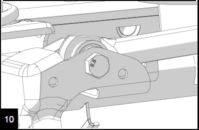
Install the u-bolt around the axle and into the bracket. Torque the nuts to 85 ft-lbs.
Torque lower control arm bolt to 125 ft-lbs. Reinstall the tires and torque the lug nuts to 90-115 ft-lbs. Remove supports and lower.
Reinstall the trackbar into the bracket using the upper hole and the factory hardware. Torque to 125 ft-lbs.
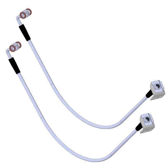
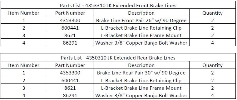
JK Extended Brake Lines
Important Notes:
Prior to beginning this or any installation read these instructions to familiarize yourself with the required steps and evaluate if you are experienced and capable to personally perform these modifications. A factory service manual should be used in conjunction with these installation instructions.
Refer to the parts list to ensure that all necessary components and hardware has been included. If any parts are missing please contact your local TeraFlex dealer for assistance.
FRONT REMOVAL
1. Park the vehicle on a level surface and set the parking brake. This installation can be done with the vehicle on the ground. Turn the tires to gain better access to brake components. Seperate the ABS line from the brake line.
2. Remove the banjo bolt from the caliper with a 9/16”. Use a pan to catch the released fluid.
Remove the soft line from the hard line with a 12mm then remove the brake line from the frame with a 10mm.
FRONT INSTALLATION
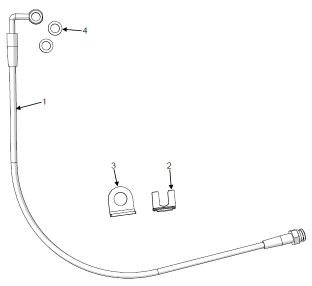
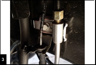
Mount the new L bracket to the frame with the original bolt. Insert the new line through the bracket. Hand tighten the hard line into the new line.
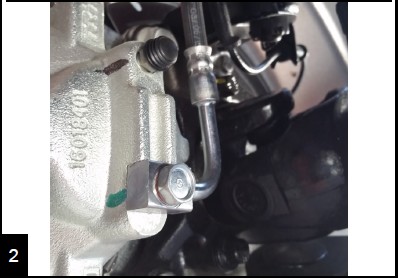
Place a new copper washer on the banjo bolt and insert though the end of the brake line. Place another copper washer between the fitting and the caliper.
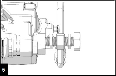
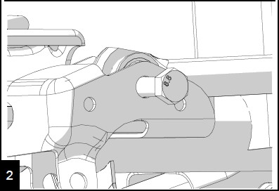
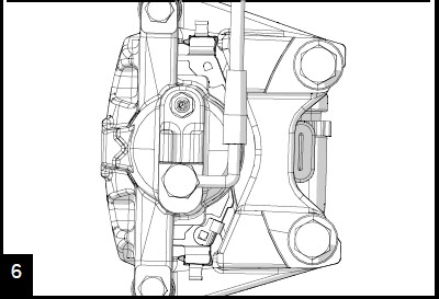
Orient the line as shown on the caliper. Torque banjo bolt to 23 ft-lbs.
Make sure the brake lines will not snag on any components as the suspension cycles and steering moves. Torque hard line connection to 14 ft-lbs and install the retainer clip. If only replacing front lines, bleed brakes according to standard procedure.
REAR REMOVAL
8. Refer to the factory service manual for lift locations. Raise and support the vehicle. Remove the tires and wheels and support the axle with a jack or jack stands.
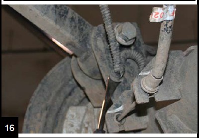
9. Remove the banjo bolt from the caliper with a 9/16”. Use a pan to catch the released fluid.
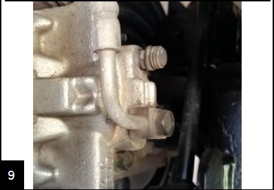
Remove the brake line from the hard line with a 12mm. Remove the line from the frame with a 10mm.
REAR INSTALLATION
Install the new L bracket onto the frame with the original bolt. Insert the new line through the bracket. Hand tighten the hard line into the new line.
Place a new copper washer on the banjo bolt and insert though the end of the brake line. Place another copper washer between the fitting and the caliper.
Orient the line as shown on the caliper. Torque banjo bolt to 23 ft-lbs.
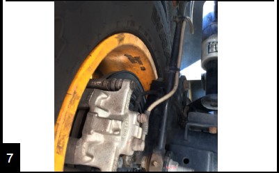
14. Be sure that the new brake line will not rub the tire or other components as the suspension cycles. Torque hard line con-nection to 14 ft-lbs. Install the retainer clip.
15. Bleed the brakes according to standard procedure. Starting with the rear right tire, the right to left, back to front.
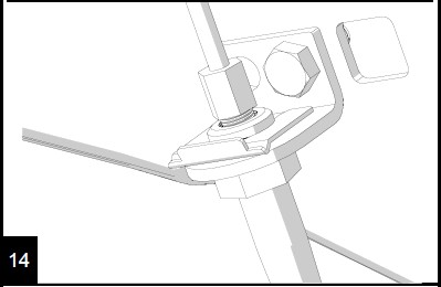
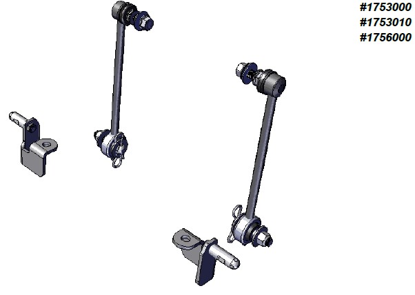
JK FRONT SWAY BAR QUICK DISCONNECTS
Important Notes:
Prior to beginning this or any installation read these instructions to familiarize yourself with the required steps and evaluate if you are experienced and capable to personally perform these modifications. A factory service manual should be used in conjunction with these installation in-structions.
Refer to the parts list to ensure that all necessary components and hardware has been included. If any parts are missing please contact your local TeraFlex dealer for assistance.
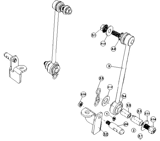
Remove the factory sway bar link.
Save the nut from the upper stud of the factory link
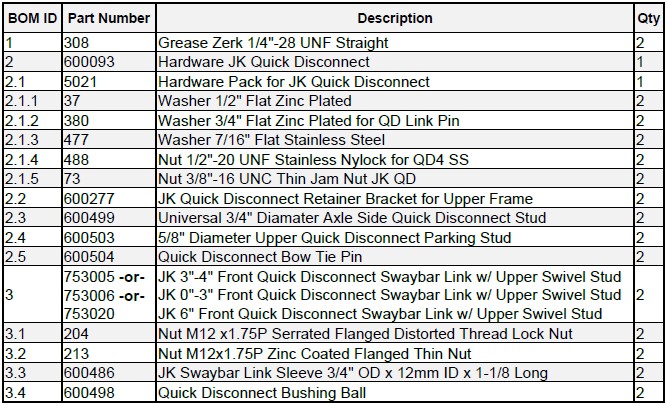
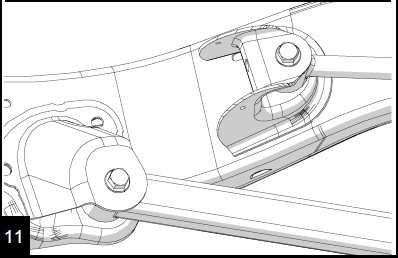
Insert 2.3 into axle bracket as shown. Place 2.1.1 and 2.1.4 on 2.3. (Use thread locking compound)
Torque 2.1.4 to 75 ft-lbs
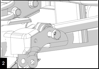
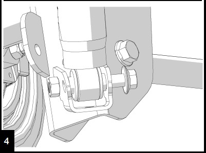
Insert the upper stud of 3 into the factory sway bar. Place 2.1.3 and 3.1 on stud. (use thread locking compound)
Torque 3.1 to 75 ft-lbs
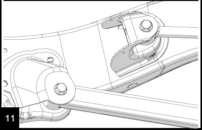
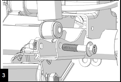
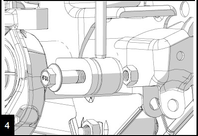
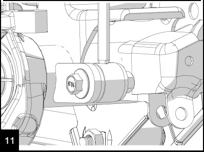
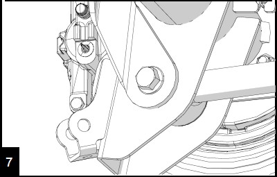
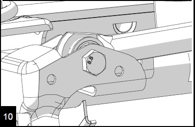
Slide lower end of 3 onto the stud installed in Step 3. Place 2.1.2 on stud and insert 2.5.
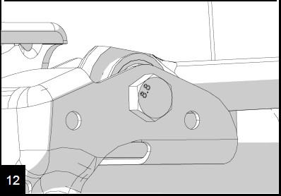
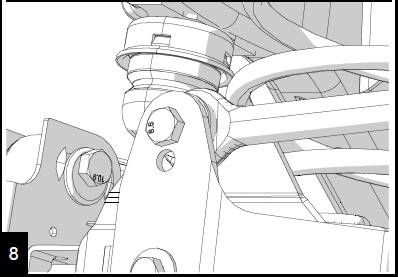
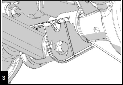
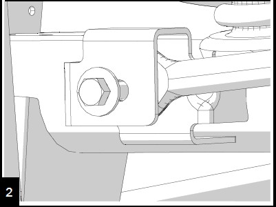
Remove the nut from the front body mount. Insert 2.4 into 2.2. Tighten 2.1.5 onto stud as shown. (Use thread locking compound)
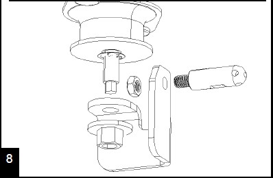
9. Slide 2.2 assembly onto the body mount and tighten body mount using nut saved from Step 2. Torque to 75 ft-lb (Use thread locking compound)
10. Repeat Steps 1 through 9 for the other side.
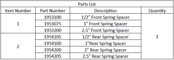
JK Spring Spacers
Important Notes:
Prior to beginning this or any installation read these instructions to familiarize yourself with the required steps and evaluate if you are experienced and capable to personally perform these modifications. A factory service manual should be used in conjunction with these installation instructions.
Refer to the parts list to ensure that all necessary components and hardware has been included. If any parts are missing please contact your local TeraFlex dealer for assistance.
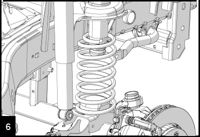
FRONT INSTALL
1. Raise and support the vehicle by the frame so the ax-les can droop. Remove the wheels and tires. See the factory service manual for safe support locations.
2. Support the front axle and disconnect the track bar at the axle with a 21mm.
Loosen all control arm bolts with a 21mm and an 18mm. DO NOT REMOVE ARMS OR BOLTS.
Disconnect the shocks at the axle with an 18mm.
Remove the brake line from the axle side brackets by prying them open. Remove the bracket with a 10mm. Lower the axle until the springs can be removed. Do not overstretch the ABS and breather lines.
Remove the spring and the spring isolator. Some applications require disconnecting the sway bar links.
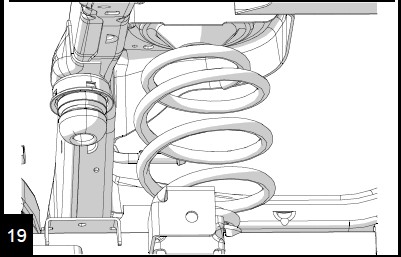
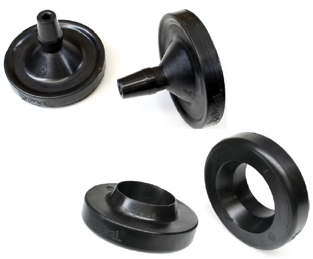
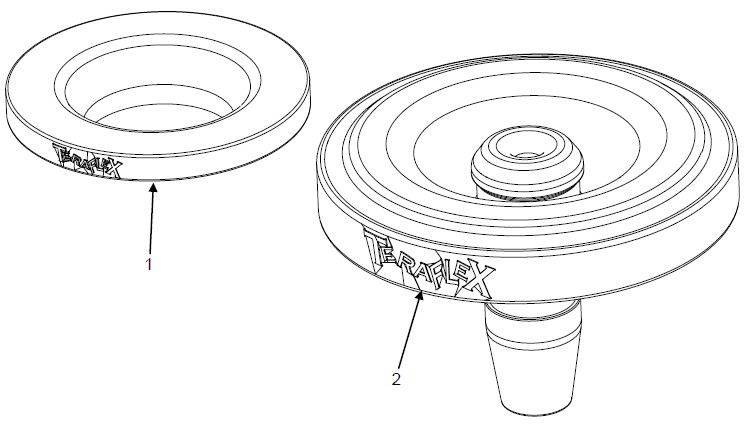
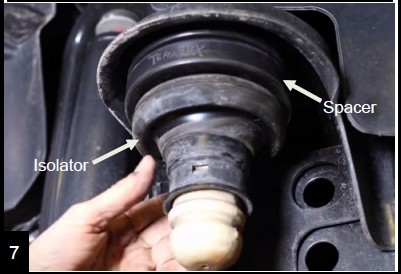
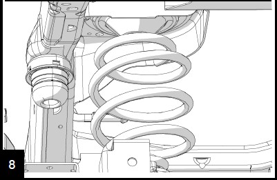
Slide the spacer, then the isolator up the jounce tube, spacer first with the flare facing down.
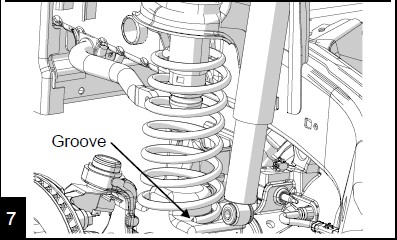
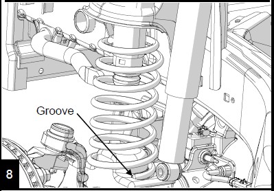
Reinstall the spring. Be sure to seat the bottom of the spring into the groove in the spring pad.
Reconnect the shocks with an 18mm. Torque to 56 ft-lbs (76 Nm). If installing on a lift, proceed to rear step 1 and in-stall the rear spacers.
Reconnect the track bar once the vehicle is on the ground. Torque bolt to 125 ft-lbs (170 Nm) Torque wheel lug nuts to 95-115 ft-lbs (129-155 Nm).
11. With the jeep on the ground at ride height, torque the upper control arms to 75ft-lbs (102 Nm), the lower control arms to 117 ft-lbs (159 Nm) at the axle and 125 ft-lbs (169 Nm) at the frame.
REAR INSTALL
1. Raise and support the vehicle by the frame so the axles can droop. Remove the wheels and tires. See the factory service manual for safe support locations.
2. Remove the track bar from the axle with a 21mm.
Loosen all control arm bolts with a 21mm and an 18mm. DO NOT REMOVE ARMS OR BOLTS.

Remove the shocks at the axle with an 18mm
Remove the clips that secure the ABS wiring harness to the upper control arm mount.
Remove the brake line mount from the frame with a 10mm.
Remove the parking brake cable bracket from the outside of the body with a 10mm deep socket and discard.
Lower the axle and remove the springs. Do not over stretch the ABS, breather and brake lines. Some kits may require disconnecting the rear sway bar links.
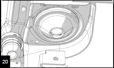
Remove the factory isolator from the upper spring perch and install onto the new spring spacer.
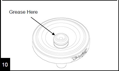
To aid in installation, apply grease to the top of the new spacer. Press the isolator and spacer assembly into the upper spring perch. You can use a piece of wood as a spacer between spring spacer and the axle, then raise the axle to press the spacer in.
Install the spring. Raise the axle high enough to reinstall the shocks. Torque shock bolts to 56 ft-lbs (76 Nm).
Reinstall the brake lines to the frame. Torque to 84 inch-lbs (9 Nm).
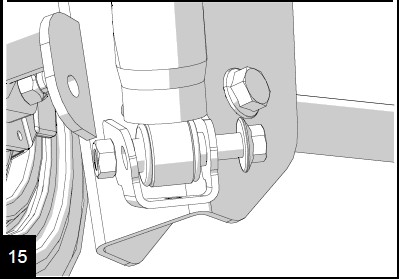
If removed, reconnect the sway bar links. Torque the top stud to 66 ft-lbs (90 Nm) and the lower bolt to 75 ft-lbs (102 Nm).
Reinstall wheels and tires. Lower to the ground and install the track bar. Torque bolt to 125 ft-lbs (170 Nm) Torque wheel lug nuts to 95-115 ft-lbs (129-155 Nm).
Torque all rear control arm bolts to 125 ft-lbs (169 Nm)
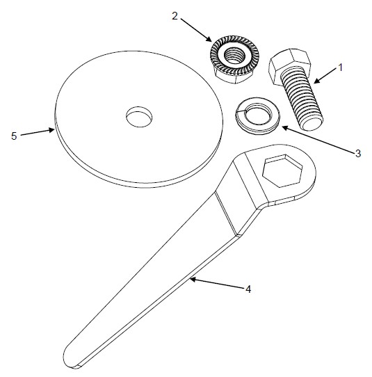
JK Rear Lower Spring Retainer
Important Notes:
Prior to beginning this or any installation read these instructions to familiarize yourself with the required steps and evaluate if you are experienced and capable to personally perform these modifications. A factory service manual should be used in conjunction with these installation instructions.
Refer to the parts list to ensure that all necessary components and hardware has been included. If any parts are missing please contact your local TeraFlex dealer for assistance.
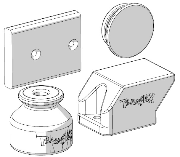
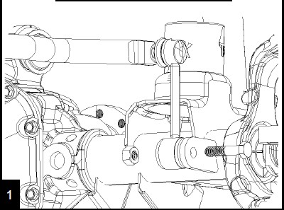
1. Park the vehicle on a level surface and set the parking brake. This installation can be done with the vehicle on the ground.
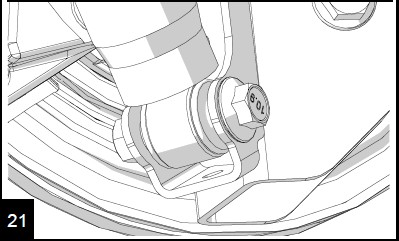
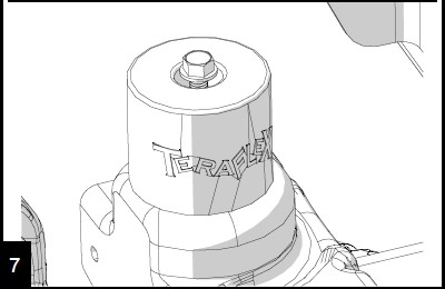
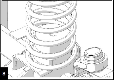
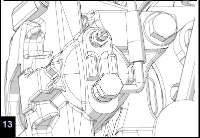
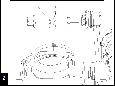
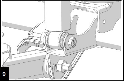
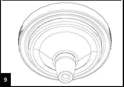
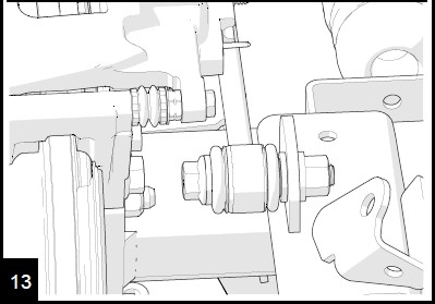
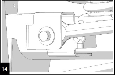
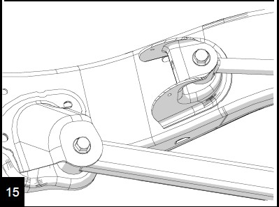
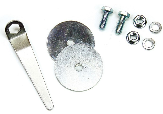
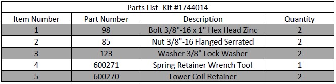
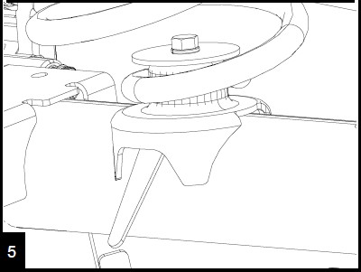
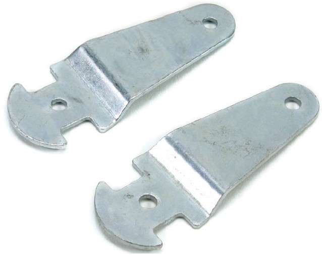
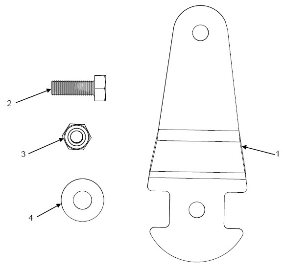
2. Place the retainer on the lower spring pad.
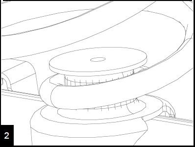
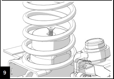
Install the 3/8” bolt and lock washer through the spring retainer and spring pad.
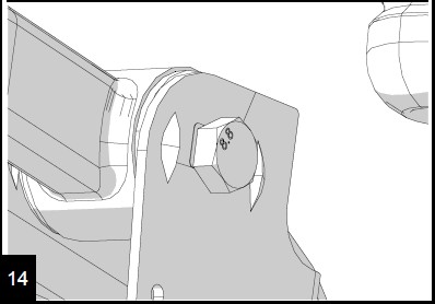
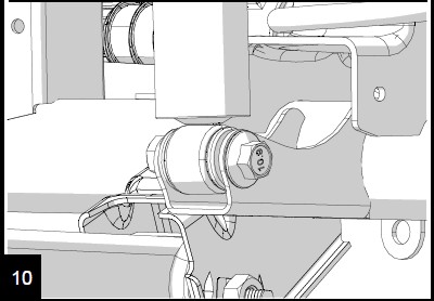
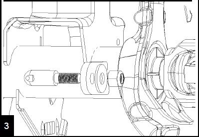
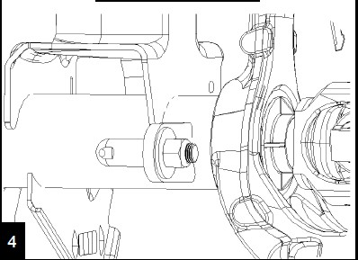
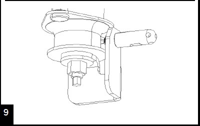
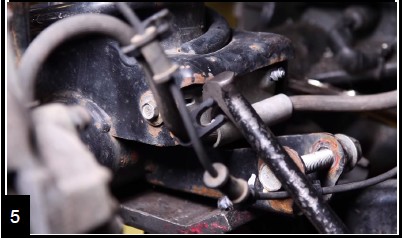
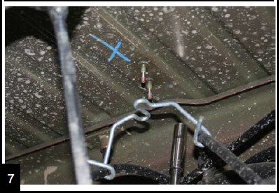
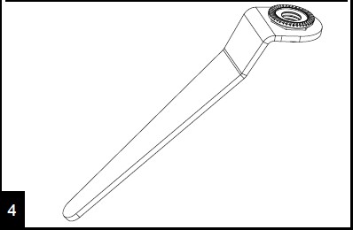
Place a nut into the provided tool. Slide the tool underneath the spring pad from the front of the axle and thread the bolt into the nut.
Torque the bolts to 30 ft-lbs (41 Nm)
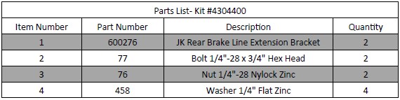
JK Rear Brake Line Extension Brackets
Important Notes:
Prior to beginning this or any installation read these instructions to familiarize yourself with the required steps and evaluate if you are experienced and capable to personally perform these modifications. A factory service manual should be used in conjunction with these installation instructions.
Refer to the parts list to ensure that all necessary components and hardware has been included. If any parts are missing please contact your local TeraFlex dealer for assistance.
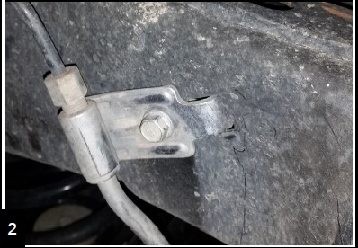
1. Park the vehicle on a level surface and set the parking brake. This installation can be done with the vehicle on the ground.
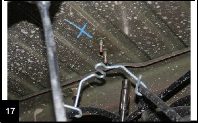
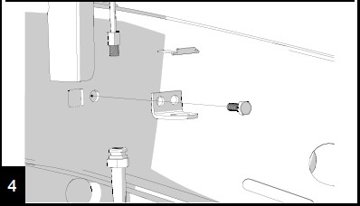
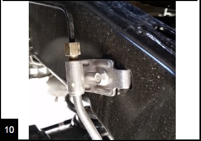
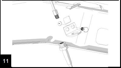
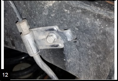
2. Unbolt the rear brake line bracket from the frame with a 10mm.
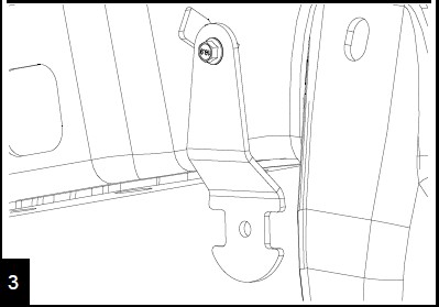
Install the bracket to the frame using the factory bolt. Note orientation with the bend inwards. Torque to 48 inch-lbs (5.4 Nm)
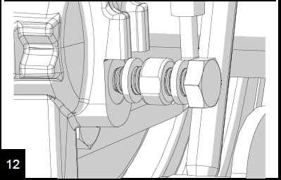
Using a 7/16” wrench and the supplied hardware, bolt the brake line to the bracket with a washer on both sides. Torque bolt to 120 inch-lbs (13 Nm)
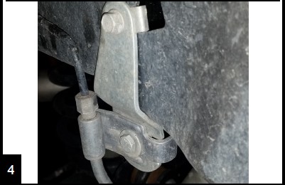
Press the hard brake line against the frame to avoid contact with the sway bar links as the suspension cycles.


