 FREE 1 to 3-Day Delivery on Orders $149+ Details

How to Install Teraflex 3 in. Elite LCG Long Arm Lift Kit w/o Shocks on your Wrangler
Installation Time
5 minutes
Tools Required
- This installation guide
- Basic mechanics tool set
- Cutting Torch or equivalent
- Welder
- Grinder with Flapper Wheel
Important Notes:
Prior to beginning this or any installation read these instructions to familiarize yourself with the required steps and evaluate if you are experienced and capable to personally perform these modifications. A factory service manual should be used in conjunction with these installation instructions.
This product requires structural welding. If you doubt you welding ability, a certified welding is always a good option.
This product will change the highway handling characteristics of your vehicle, exercise caution.
2010-11 models will require cutting and modifying the exhaust.
Refer to the parts list to ensure that all necessary components and hardware has been included. If any parts are missing please contact your local TeraFlex dealer for assistance.
Parts List
| Item Number | Part Number | Description | Quantity |
|---|---|---|---|
| 1 | 657839 | JK Front Upper Long FlexArm w/ Joint | 2 |
| 2 | 653719 | JK Front Lower Long FlexArm w/ Joint | 2 |
| 3 | 654729 | Right JK Rear Lower Long FlexArm w/ Joint | 1 |
| 4 | 654719 | Left JK Rear Lower Long FlexArm w/ Joint | 1 |
| 5 | 654820 | JK Rear Upper Long FlexArm w/ Joint | 2 |
| 6 | 4915161 | Large Clevite Rubber Bushing | 4 |
| 7 | 308 | Grease Zerk 1/4"-28 Straight | 4 |
| 8 | 20890 | Grease Zerk 1/4"-28 90 Degree | 2 |
| 9 | 3088 | Grease Zerk 1/4"-28 Flush Hex Style | 2 |
| 10 | 307 | Set Screw 1/4"-28 x 1/4" Long | 8 |
| 11 | 750860 | JK Rear Passenger Side Bracket OEM Width | 1 |
| 12 | 750870 | JK Rear Driver Side Bracket OEM Width | 1 |
| 13 | 953020 | JK Front Right FlexArm Mount | 1 |
| 14 | 953010 | JK Front Left FlexArm Mount | 1 |
| 15 | 954021 | JK Rear Driver Side Frame Plate | 1 |
| 16 | 954022 | JK Rear Passenger Side Frame Plate | 1 |
| 17 | 243 | Bolt M12-1.75x130mm Long Grade 10.9 | 4 |
| 18 | 111 | Bolt 9/16"-12 x 3.5" Long Hex Head Zinc | 4 |
| 19 | 277 | Bolt 9/16"-12 x 4.5" Long Hex Head Zinc | 4 |
| 20 | 178 | Nut 9/16"x12 Nylock Zinc | 8 |
| 21 | 318 | Washer 9/16" Flat Zinc | 12 |
| 22 | 112 | Bolt M12-1.5 x 40mm Long Full Thread | 2 |
| 23 | 134 | Washer 7/16" Flat Zinc | 2 |
| 24 | 611012 | Rear Upper Control Arm Bushing | 2 |
Important Notes
This installation is much easier if the Jeep is low on gas as you will be removing the fuel tank. If you have access to a lift, the best place to position the lift arms is directly under the body mounts to allow access for cutting, welding, axle droop, and placement of your new brackets. We recommend adding a jack stand to the rear of the vehicle for extra support. Place the vehicle in neutral to allow for easy driveline removal.
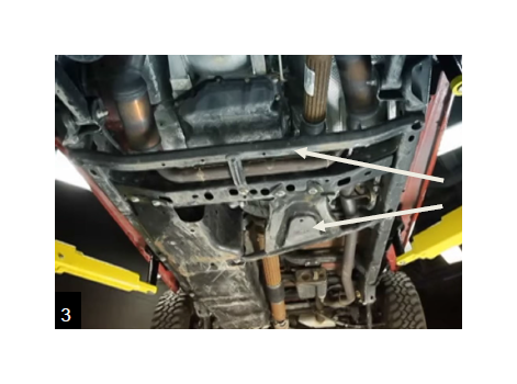
1. Remove the transfer case skid plate and exhaust skid plate/cross member. The exhaust skid plate will not be reused.
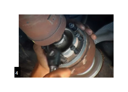
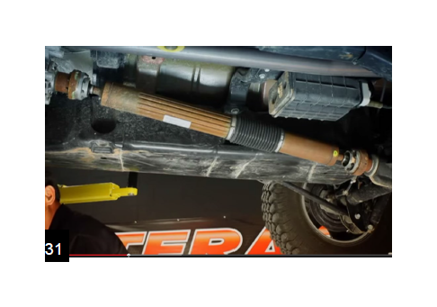
2. Skip steps 4-5 if you are not replacing the factory drivelines. Make a mark across the flanges at the axles and transfer case. Remove the 8 bolts at each CV end with a 5/16” socket. The front axle end is 4 bolts and a 15mm.
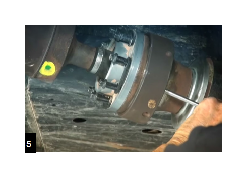
3. Through the two access holes in the rear flange, use a punch to free the driveline from the axle. Do not let the axle hang from the CV joint. The transfer case end will be easier to remove.
4. Removing the fuel tank is optional but highly recommended. Remove the filler neck with a 6mm.
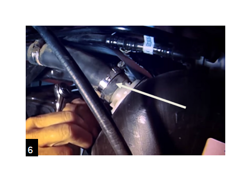
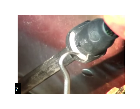
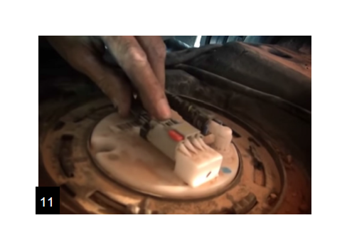
5. Use a screwdriver or equivalent to depress the white release to disconnect the vent line.
6. Disconnect the supply and return lines by squeezing the blue tabs. Caution! The supply line may still be under pressure. Have a rag ready to absorb any fuel leaks.
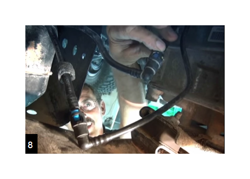
7. Be sure to cap/protect any open fuel lines. On most models the supply and return lines can be snapped together.
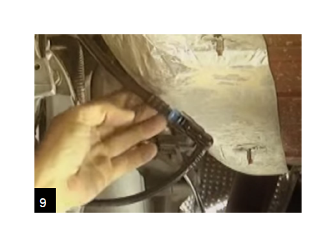
8. Disconnect the EVAP lines that run between the EVAP system and the fuel tank.
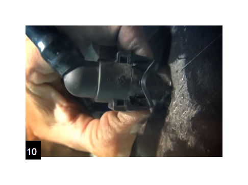
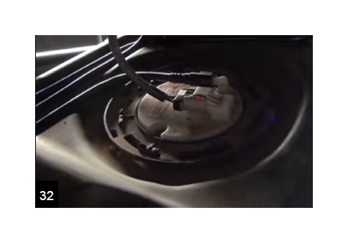
9. Remove the 8 bolts supporting the tank and slowly lower it. Beware of fuel/electrical lines that are still connected. Once you have access, remove the remaining electrical connections.
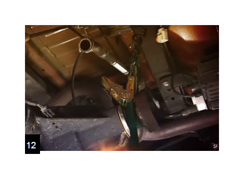
10. Lower the rear axle. Use a small strap around the rear pinion to help keep the axle in place, once the control arms are removed.
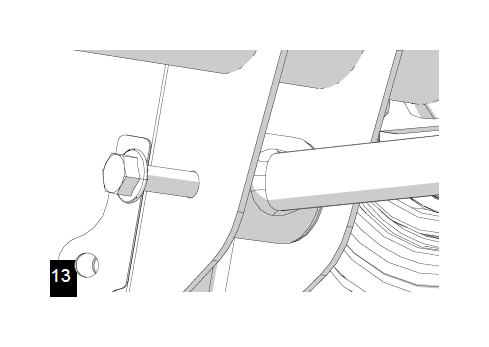
11. With the axle supported, remove all four rear control arms with a 21mm or an 18mm. Keep the hardware. Most nuts are captured nuts.
12. Support the front axle, un-bolt the bottom of the shocks with an 18mm (See 999207 Shocks/Front Removal).
13. Remove/un-clip all hoses and electrical wires that may bind. Lower the axle. Place a strap on the pinion.
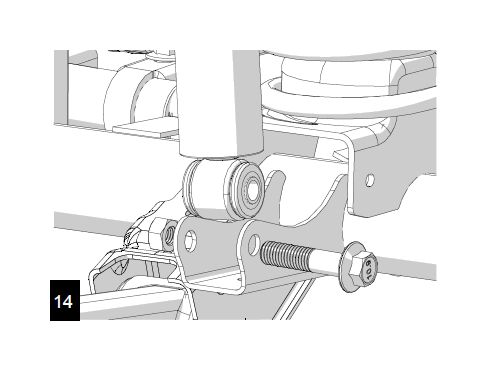
14. Remove all four front control arms with a 21mm or an 18mm. Keep the hardware.
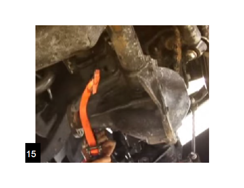
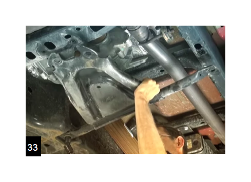
15. Un-clip all wire loom and fuel lines near where you will be cutting and welding. Tuck them above the frame or where they will not be damaged. With all control arms removed, begin cutting and removing the control arm brackets. Take extra care not to cut into the frame. Pay special attention to the direction of your flames and sparks as well as any hoses or wires that could be effected by the heat. Beware of any brake lines above the upper control arm mount on the drivers side as well. Avoid long, vertical welds on the frame; this may lead to cracking and frame failure.
16. After cutting is complete, grind down all remaining slag and metal to make a smooth surface for mounting the new brackets. We suggest using a flapper wheel on a 4” grinder.
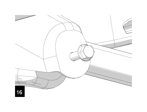
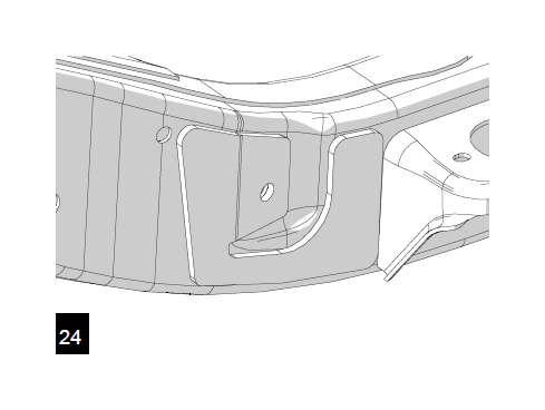
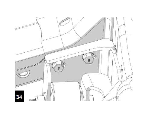
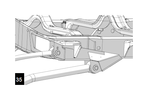
17. The front brackets index to a hole in the bottom of the frame and two bolts in the cross-member. Replace the cross-member bolts with longer, provided bolts. 2010-2011 See page 9-10 now.
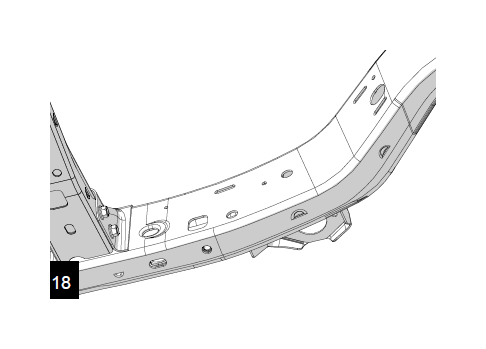
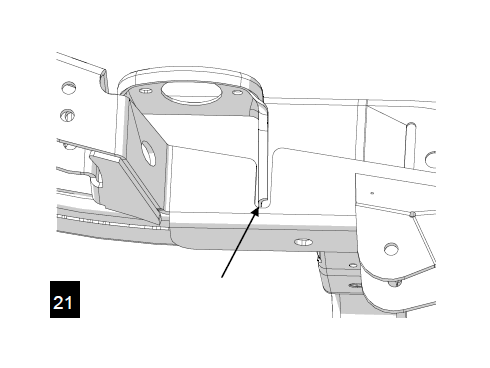
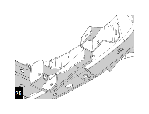
18. The rear gusset plate locates to a control arm hole in the frame. This will be welded in place before the rear bracket.
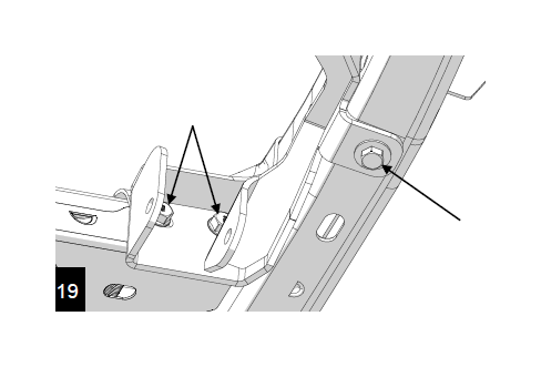
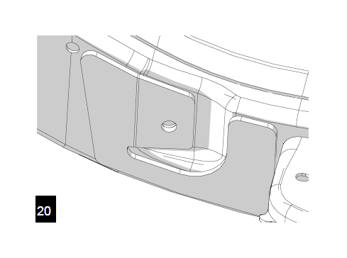
19. The rear brackets index around a body mount bracket. Cen-ter the slot in the bracket around the body mount.
20. Mark where the brackets and gussets will contact the frame. Clean off any paint within 1” of where welding will occur. A clean surface is key to a strong, lasting weld.
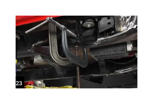
21. Use C-clamps to eliminate any gaps between the new brack-ets and the frame. Do several tack welds around the bracket to keep it from warping as you weld. Minimizing the bracket gap will make for a much better weld.
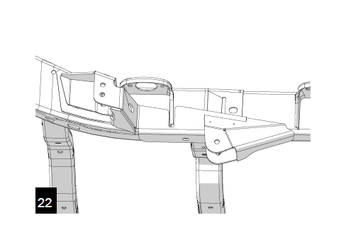
22. Weld the rear frame gussets on first. The rear brackets will weld to the new gussets. Weld on the rear brackets next.
23. Weld the front brackets. Take some time after welding to clean these sections and paint to prevent rust.
24. Lengthen the new arms. (Estimated lengths for a 4” lift, center to center)
Front Uppers: 27 3/4”
Front Lowers:33 11/16”
Rear Uppers: 19 1/2”
Rear Lowers: 35 1/8”
All lifts must have a four wheel alignment after installation.
This is essential to have a great driving Jeep.
25. Install the new long arms with the flex joints at the axles. The new hardware will be used in the new frame brackets, Original hardware will be used at the axles. Do not completely tighten any joint or bushing until the Jeep is on the ground. This is important for bushing life, flex and ride quality.
26. For most applications the rear upper arms will be mounted in the lower holes. Use the 9/16” x3.5” bolt and washers.
27. The rear lower arms are mounted with the bends up and in for maximum clearance. Use the 9/16” x 4.5” bolt and washers.

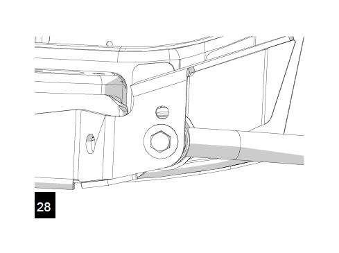
28. Raise the axle and reinstall the front shocks. (See 999207 Shocks/Front Installation)
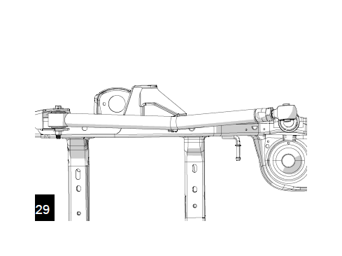
29. Reinstall drivelines if applicable. Align the flange marks. At the transfer case; torque to 15 ft-lbs. Front axle flange; toque to 81 ft-lbs. Rear axle flange; torque to 15 ft-lbs.
30. Reinstall the fuel tank in the reverse order removed. Don’t forget any fuel lines, EVAP lines or electrical connections. Torque strap bolts to 30 ft-lbs.
31. Reinstall the transfer case skid plate. Torque bolts to 48 ft-lbs.
32. Torque the front bracket cross-member bolts to 90 ft-lbs.
33. Reinstall the tires, torque lug nuts to 95-110 ft-lbs. Remove supports and lower the vehicle to the ground. With the vehicle on the ground, torque front upper control arms to 75 ft-lbs, all other control arms to 125 ft-lbs.
2010-11 Exhaust Modification
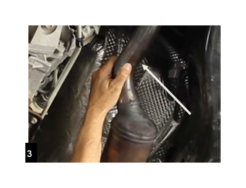
These years have a large, intrusive catalytic con-verter which will need to be cut out and moved. While orienting your catalytic converter, keep in mind that you may need access to your O2 sensor sooner or later. Place it in a location that will allow for removal of the sensor probe (1”).
Disconnect the sensor from the wiring harness by pinching the release and separating the plug.
1. Use a reciprocating saw and cut as straight as possible in the straight pipe area just past the bend in front of the converter.
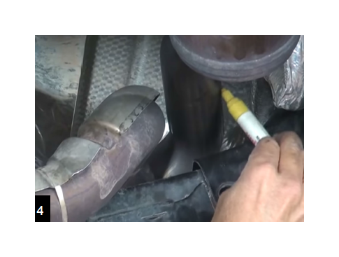
2. For the rear cut, give yourself plenty of room and cut in a straight section of pipe at least 2.5” from the bend into the converter.
3. Clean frame and front bracket of paint everywhere you will be welding. Clamp the bracket into place to close any gaps between the bracket and frame. Weld it on.
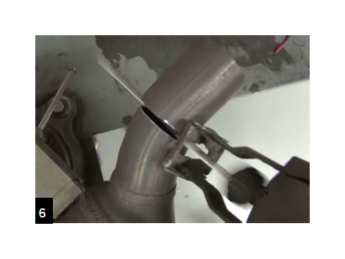
4. Cut about 2.5” of pipe off of the rear of the converter. Cut as square as possible, you will be reusing this section of pipe.
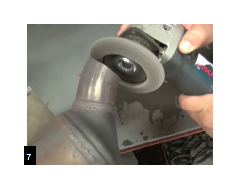
5. Use a grinder and clean up the cut ends of the exhaust pipe.
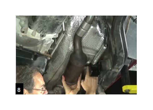
6. With the bracket welded in, hold the converter in place. The 2.5” section that was removed from the back will be moved to the front. You can either butt weld the pipes back together or use couplings.
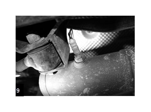
7. If the converter is properly oriented, the O2 sensor will be easy to remove and clear the new control arm bracket. With all clearances checked, weld in place.
PRODUCT INFORMATION
MAINTENANCE INFORMATION:
It is the buyer’s responsibility to have all suspension, drivetrain, steering, and other components checked for proper tightness and torque after the first 100 miles and every 3000 miles after that.
NOTICE TO INSTALLER:
The enclosed “Warning to Driver” sticker must be installed in the vehicle in driver’s view. This sticker is to act as a constant safety reminder when operating the vehicle. It is your responsibility as the equipment installer to install the provided sticker and to forward the product instructions to the vehicle’s owner for review. If a “Warning to Driver” sticker or product installation guide were not included in the kit, FREE replacement stickers and instructions are available by request. It is the installer’s duty to ensure a safe and controllable vehicle after the modifications have been performed.
WARNING:
Neither the seller nor the manufacturer will be liable for any loss, damage, or injury directly or indirectly arising from the use of or inability to determine the use of these products. Before using, the user shall determine the suitability of the products for its intended use, and the user shall assume all responsibility and risk in connection therewith.
WARNING TO DRIVER:
This vehicle has been modified to enhance off road performance and has unique handling characteristics. Use in harsh environments can cause extreme stress on the components. Vehicle should be inspected after being off road to make sure that all the components are in working order and safe to travel on the highway. All fasteners should be checked so that they are at the correct torque specifications as the vibration and stresses from off roading may cause critical fasteners to work loose. Extra care should be taken to inspect the critical components, steering, and brake systems. During each oil change components such as arms, tie rod ends, etc should be greased and checked for excessive wear. Any worn components should be replaced. When returning to the pavement always set or restore tire air pressure to the factory recommendation and connect or engage any disabled sway bar mechanisms. Because of the higher center of gravity and larger tires, this vehicle handles and reacts differently than many passenger cars, both on and off road. You must drive it safely! Extreme care should be taken to prevent vehicle rollover or loss of control, which can result in serious injury or death. Avoid sudden sharp turns or abrupt maneuvers. Generally, braking performance and capabilities are decreased when significantly larger/heavier tires are used, especially when used in combination with transfer case low-range reduction kits. Take this into consideration while driving. Do not add, alter or fabricate any factory or aftermarket parts to increase vehicle height over the intended height of the Tera-Flex product purchased. Mixing component brand is not recommended. TeraFlex Inc. will not be responsible for any altered product or any improper installation or use of our products. We will be happy to answer any questions concerning the design, function, and correct use of our products. It is ultimately the buyer’s respon-sibility to have all bolts/nuts checked for tightness after the first 100 miles and then every 3000 miles. Wheel alignment, steering system, suspension and drive line systems must be inspected by a qualified professional mechanic at least every 3000 miles.
TERAFLEX PRODUCT WARRANTY:
TeraFlex Inc. warrants TeraFlex Suspension products to the original retail purchaser to be free of defects in material and workmanship for as long as the original purchaser owns the vehicle on which products were originally installed.
Failure to complete regular maintenance (grease every 3000 miles) on TeraFlex FlexArms will void this warranty. All other conditions of the standard TeraFlex product warranty apply.
All TeraLow products are covered by the TeraFlex two (2) year warranty to be free of defects in material and workmanship for two years from date purchased.
TeraFlex axles are covered by a 12-month warranty to be free of defects in materials and workmanship.
This warranty does not cover or include product finish, improperly installed or applied products, improperly maintained products, products or components used for racing or competition or damage due to abuse or neglect, products that fail due to the use of larger tire and wheel combinations.
All returns must be accompanied by an original invoice. It is the customer’s responsibility to remove the product from the vehicle. Shipping charges are the respon-sibility of the customer. TeraFlex Inc. will pay the return freight if the product meets the terms of warranty.
This warranty is for the replacement or repair of defective TeraFlex products only and does not include freight charges, labor charges for removal of or installation of TeraFlex or related products or components, costs incurred due to down time of the vehicle, or lost profits due to vehicle down time.
A returned goods authorization number (RGA#) must accompany any returned products. For more information please contact a TeraFlex customer service repre-sentative.
COPYRIGHT
©Copyright 2014. All rights reserved, TeraFlex Inc. Reproduction of this catalog and/or any of its contents without written permission is strictly prohibited.
TeraFlex® is a registered trademark of TeraFlex Inc. All trade names and logos including but not limited to TeraFlex, FlexArms, RockGuard, Monster, and LCG are protected by law and duplication of trade names and/or logos are strictly prohibited.
TeraFlex Inc. reserves the right to update, discontinue, redesign, modify finish, part number or component build parts if deemed necessary without written notice. TeraFlex Inc., and any associated dealers are not responsible for misprints or typographical errors that may have inadvertently been made within this instruction sheet.
