 FREE 1 to 3-Day Delivery on Orders $149+ Details

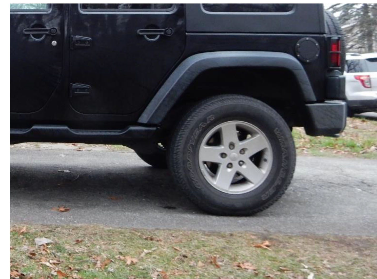
How To Install a Teraflex 2.5 IN. Lift Kit w/ Shocks on your 2007-2016 Jeep Wrangler JK 4 Door
Installation Time
6 hours
Tools Required
- Floor Jack
- Jack Stands
- Ratchet
- Torque Wrench
- 15mm Socket
- 15mm Wrench
- 16mm Socket
- 16mm Wrench
- 18mm Socket
- 18mm Wrench
- 19mm Socket
- 19mm Wrench
- 21mm Socket
- 21mm Wrench
- Dykes

Shop Parts in this Guide
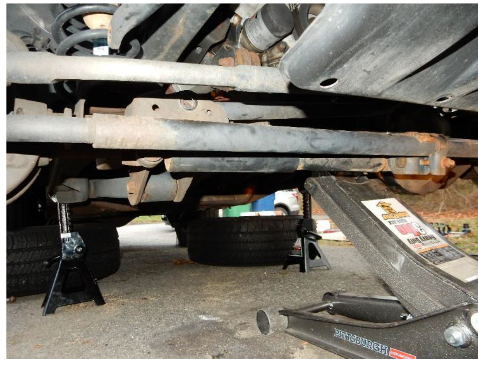
Park on level ground and chock wheels – for rear install, chock front wheels – for front install, chock rear wheels.
Installation Instructions:
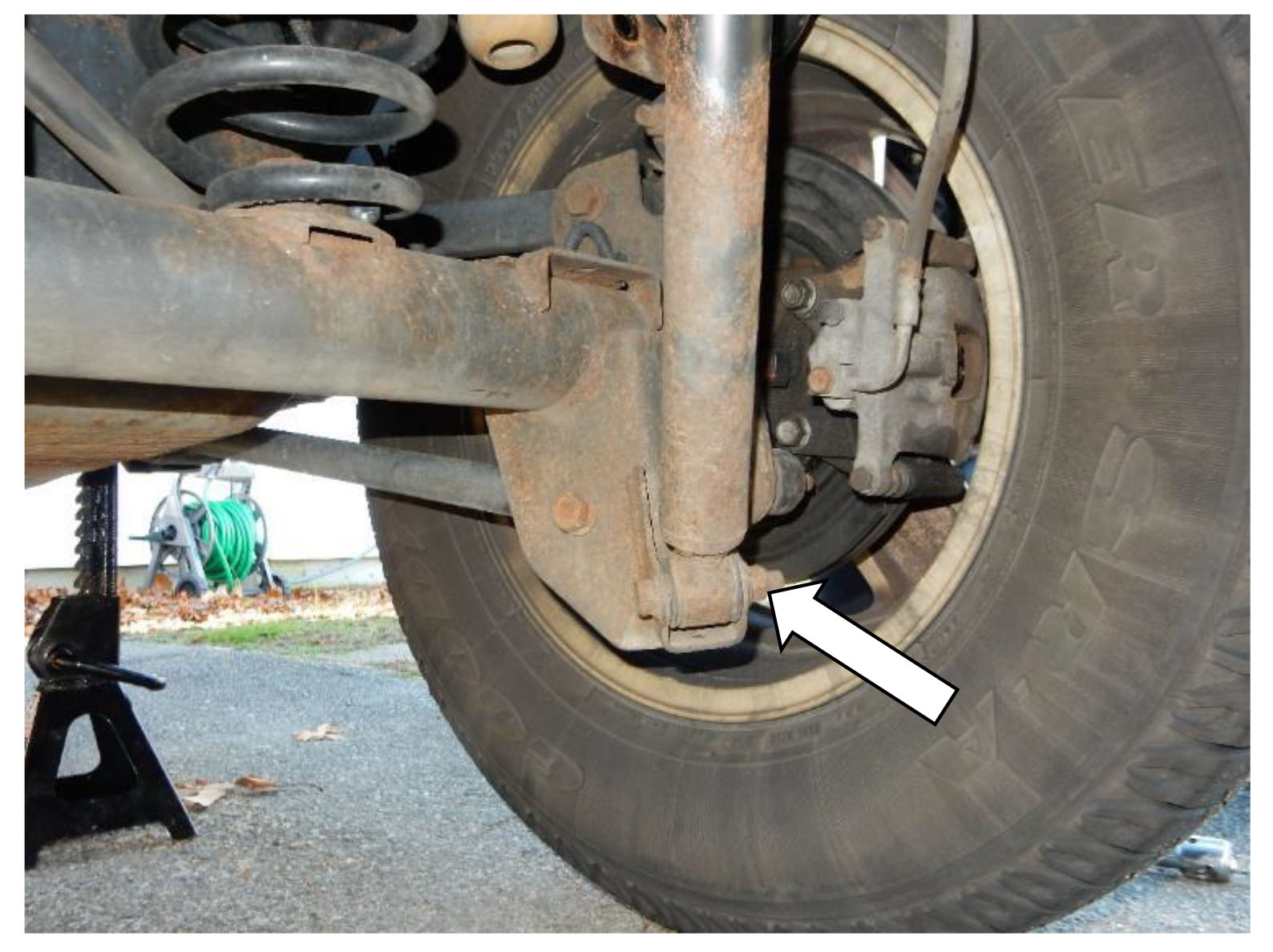
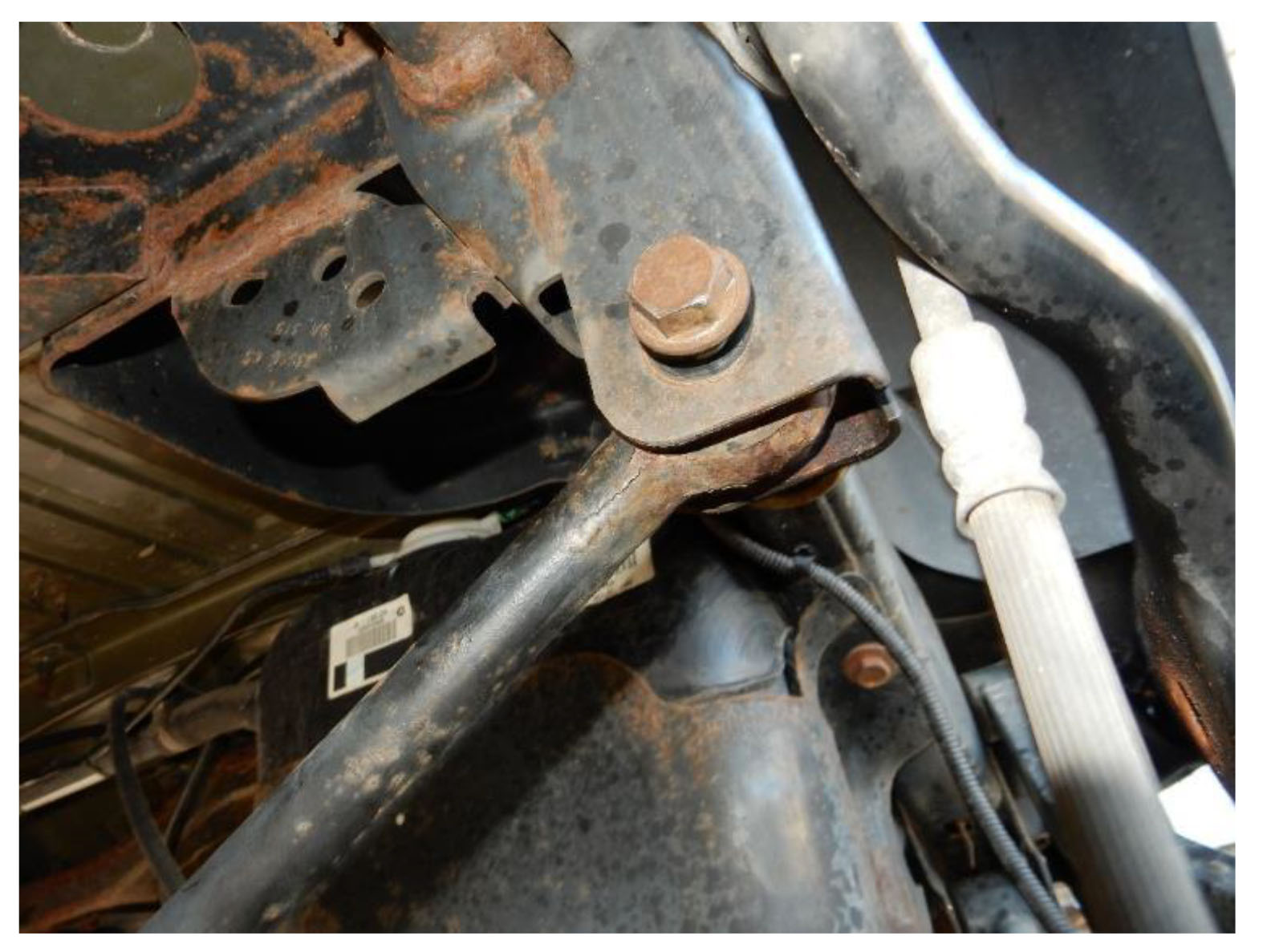
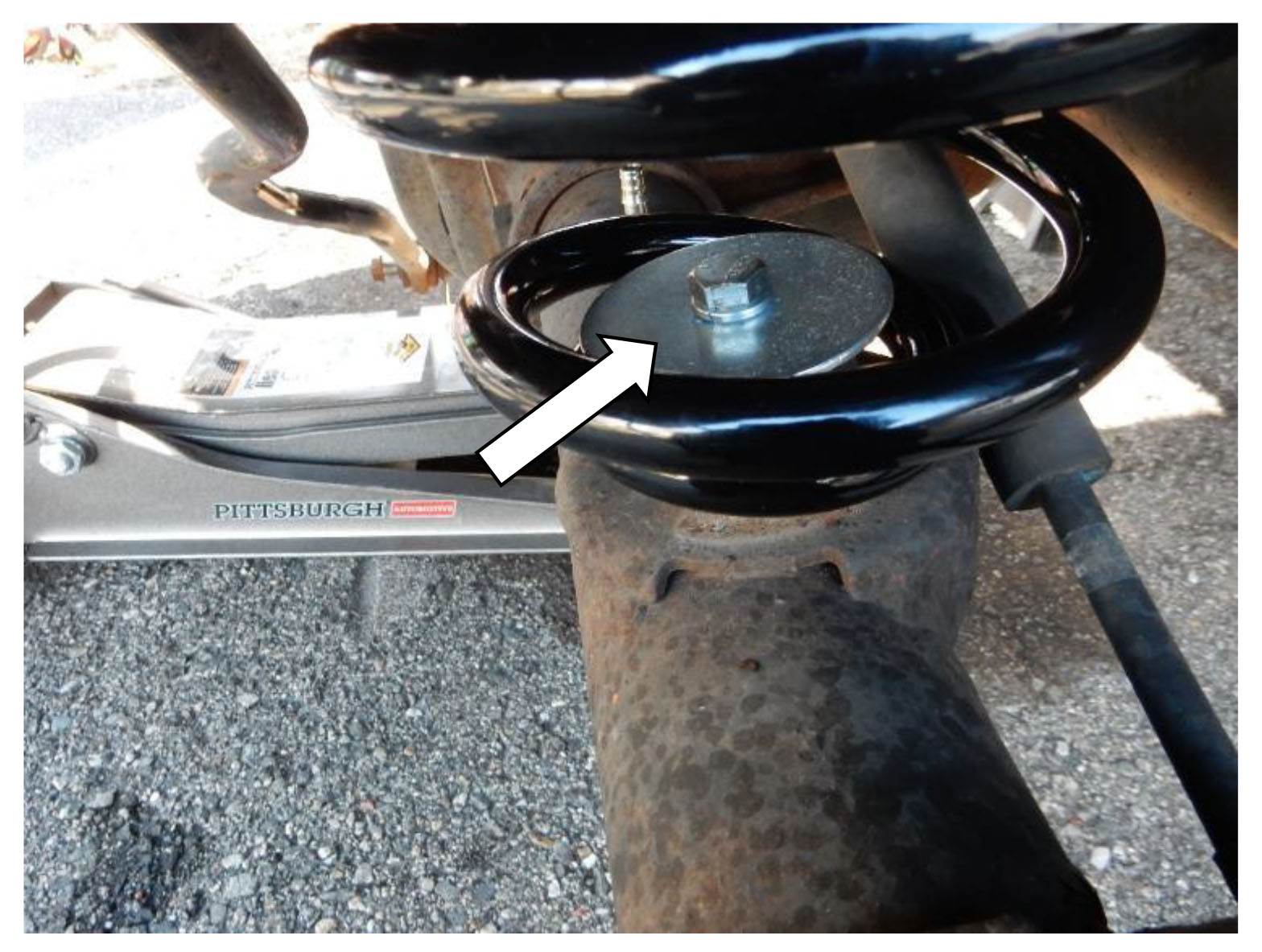
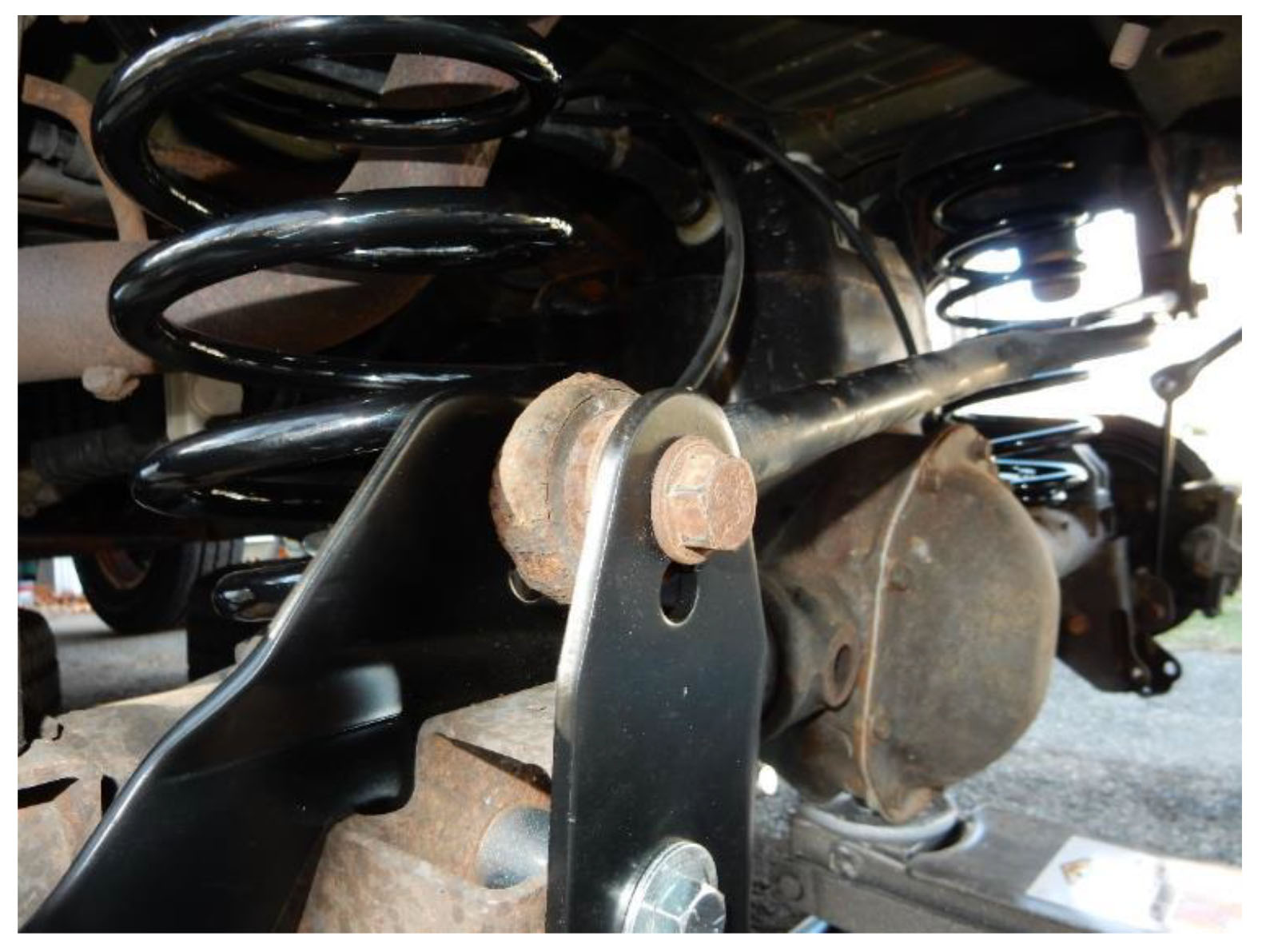
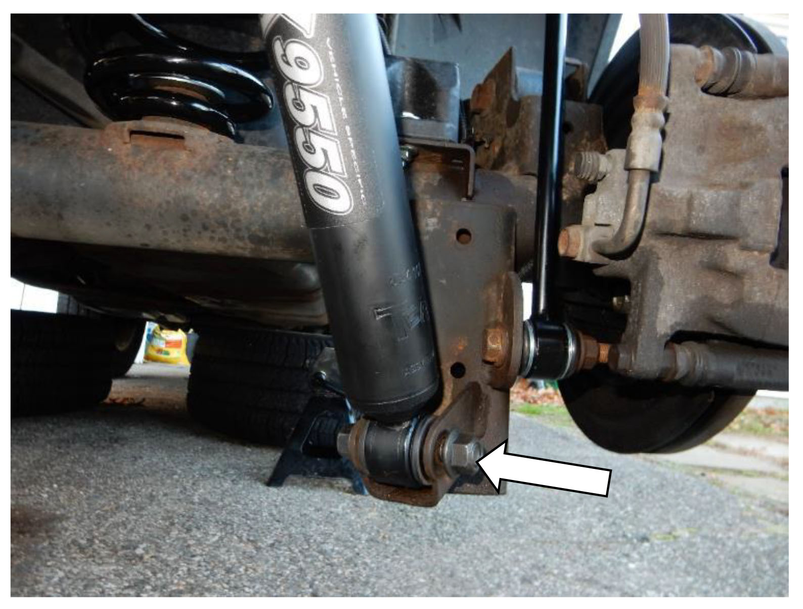
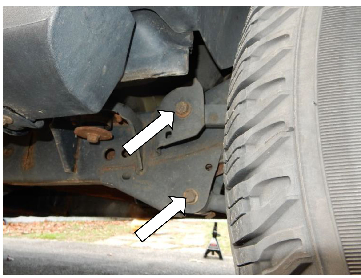
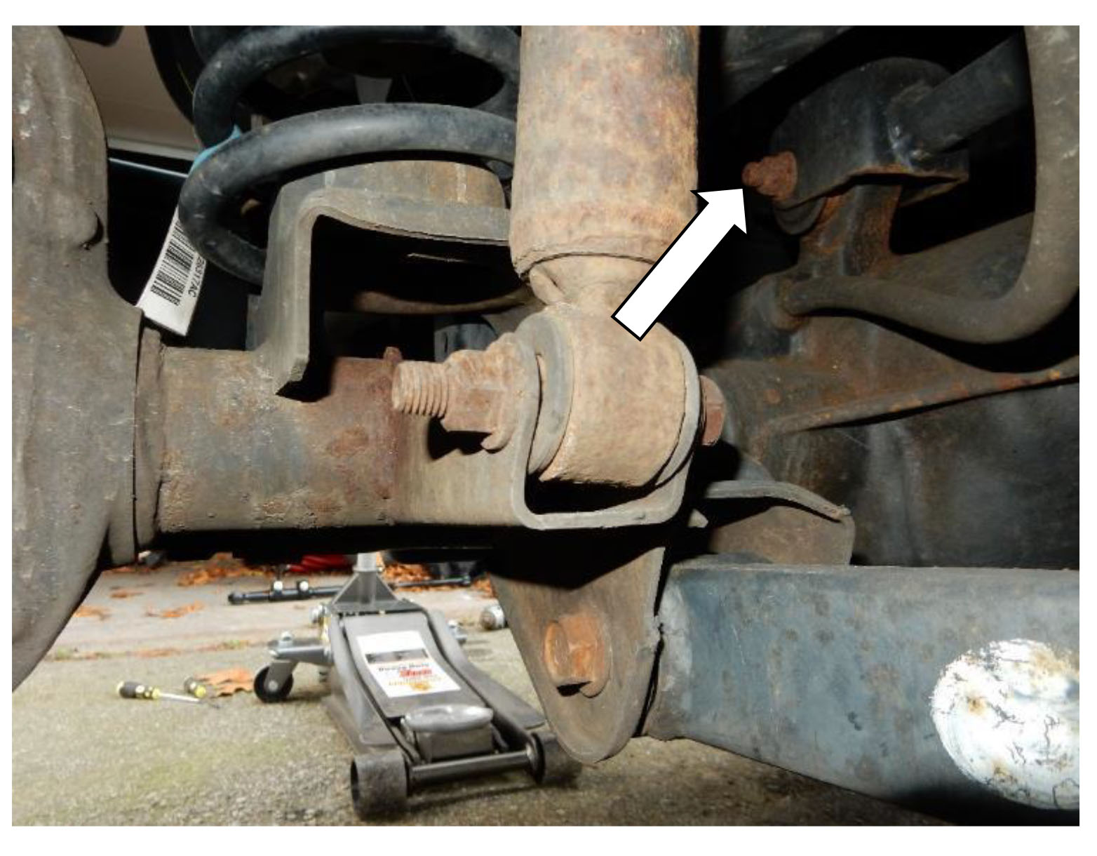
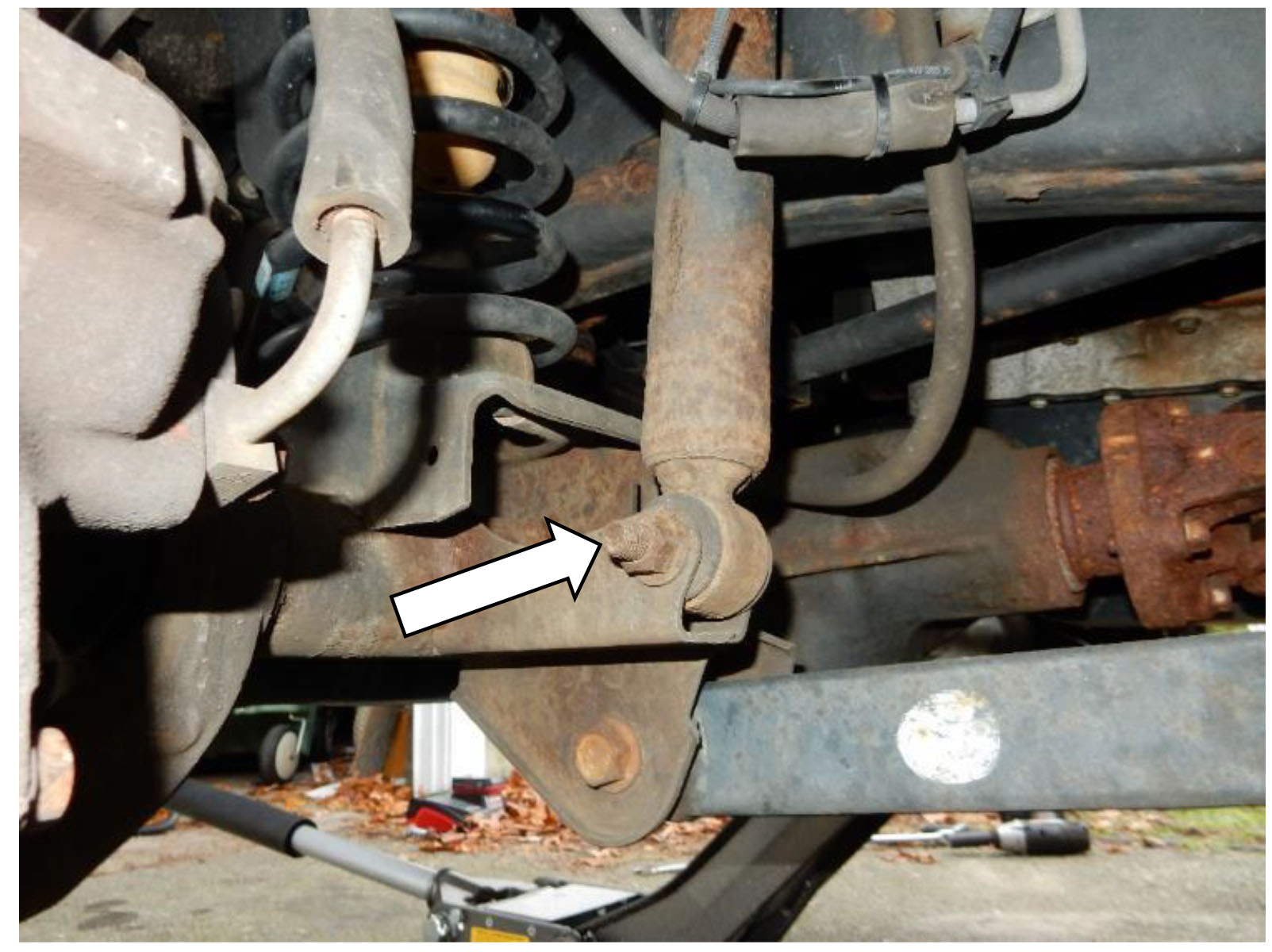
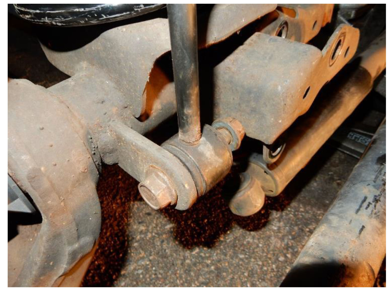
1. Using a 21mm socket, remove the bolt connecting the rear track bar to the axle bracket.
Note: A flag nut is used on this bolt.
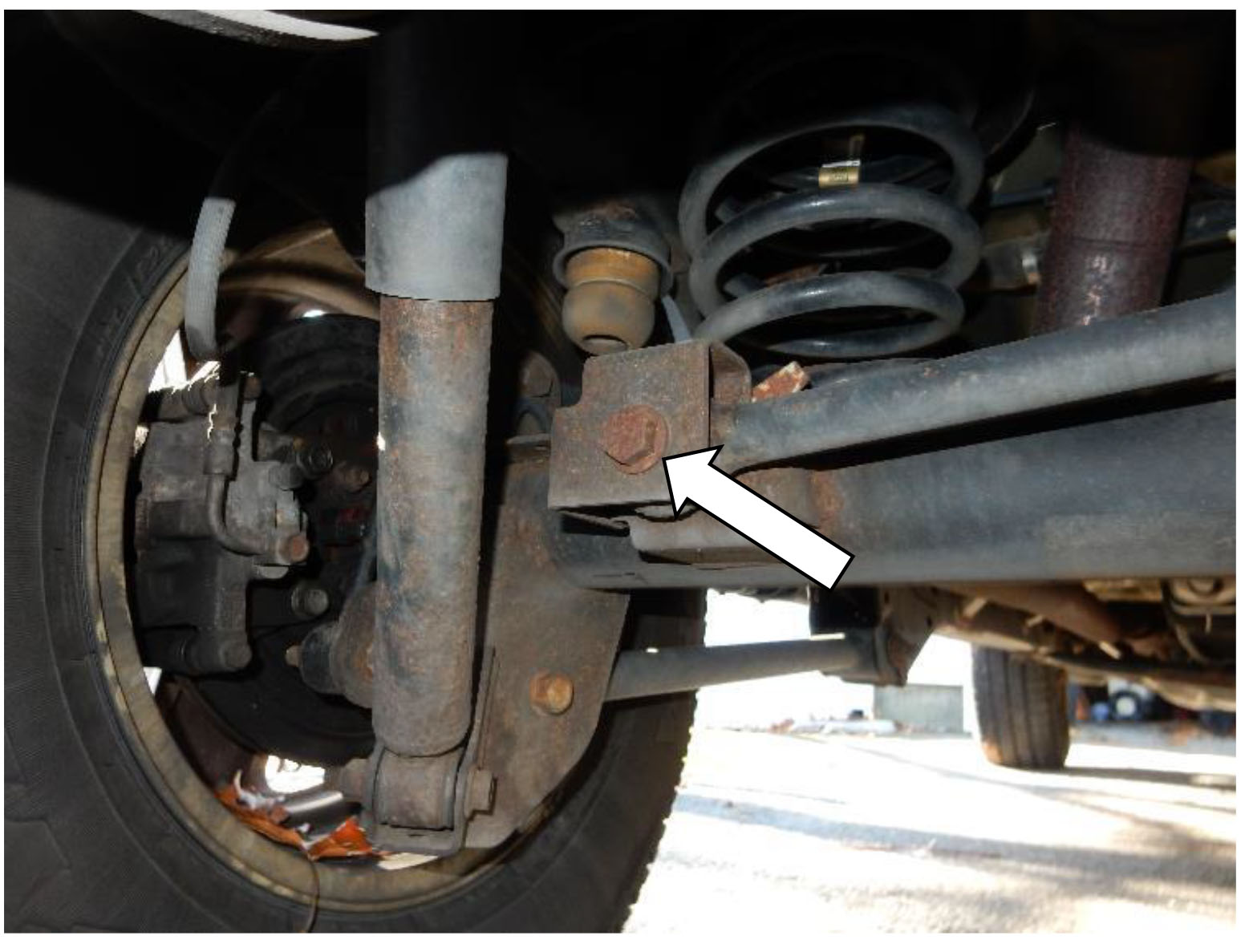
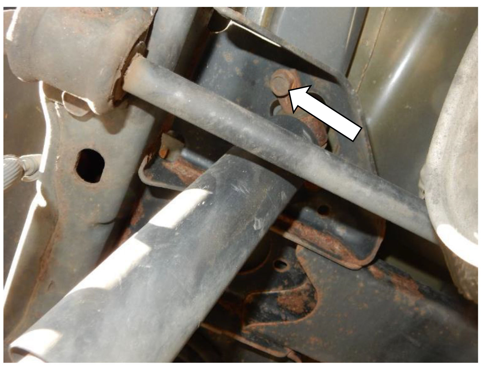
2. Using a 21mm socket and wrench, remove the bolt connecting the rear track bar to the frame, remove the rear track bar.
3. Using a 21mm socket, loosen the bolts on the rear upper control arm on the driver and passenger sides.
Note: DO NOT REMOVE THE BOLTS OR CONTROL ARMS
4. Using a 21mm socket, loosen the bolts on the rear lower control arm on the driver and passenger sides.
Note: DO NOT REMOVE THE BOLTS OR CONTROL ARMS
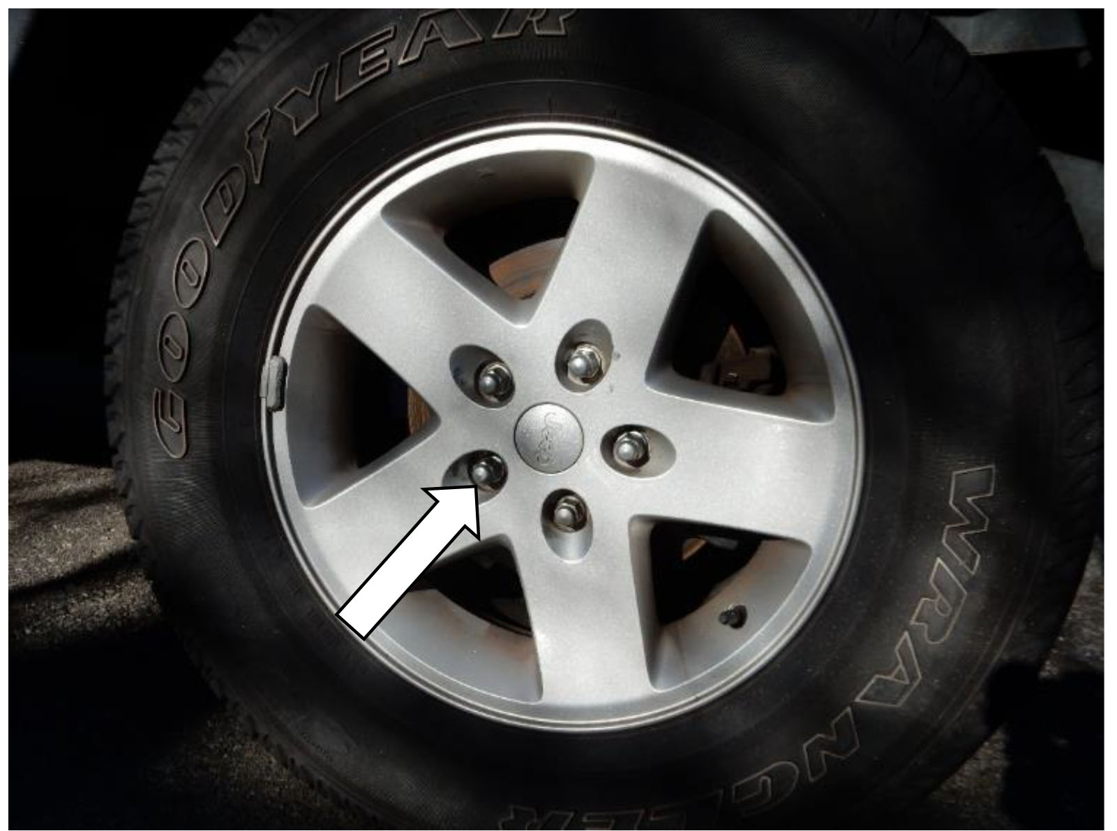
5. Using a 19mm socket, break loose the lug nuts on the rear wheels, do not remove the nuts completely.
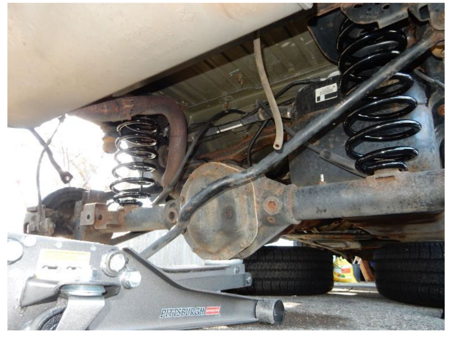
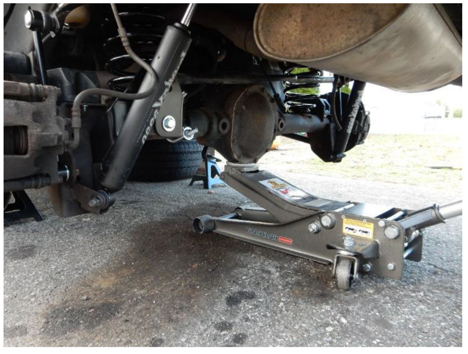
6. Using a floor jack, aligned under the rear differential, lift the Jeep high enough to raise the rear wheels off the ground.
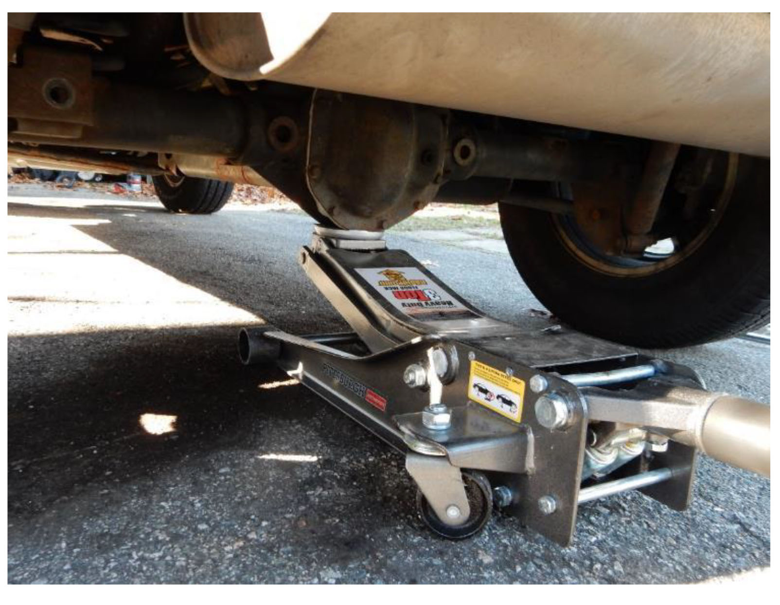
7. Place jack stands under the frame, lower the floor jack until the vehicles weight is fully supported by the jack stands.
Note: Leave the floor jack under the rear axle to be used later.
8. Using a 19mm socket, remove the lug nuts from the rear wheels. Remove rear wheels from the driver and passenger sides.
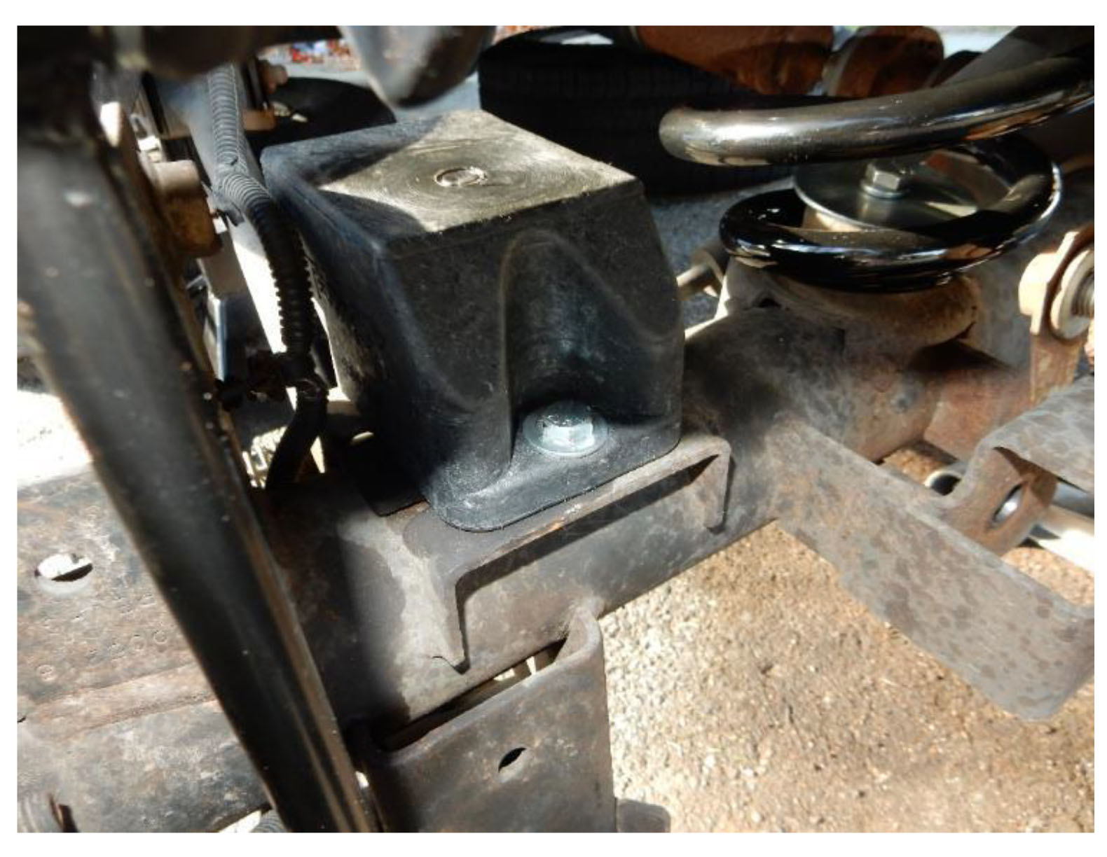
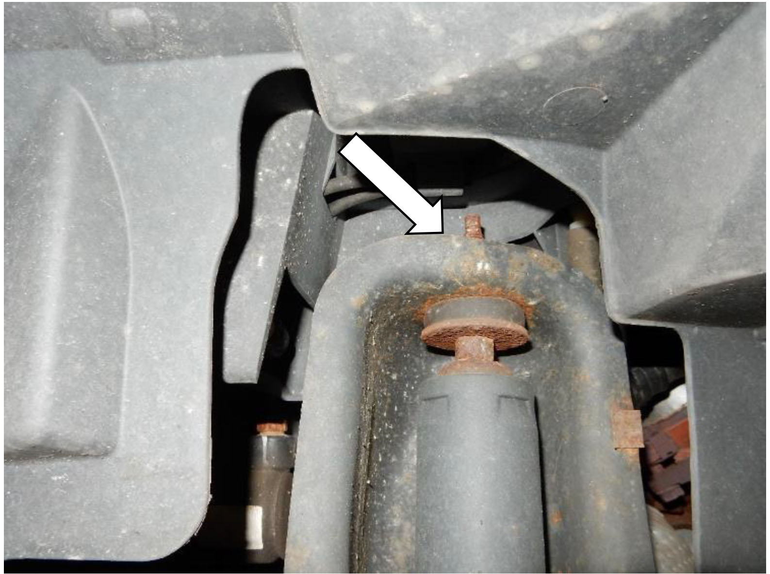
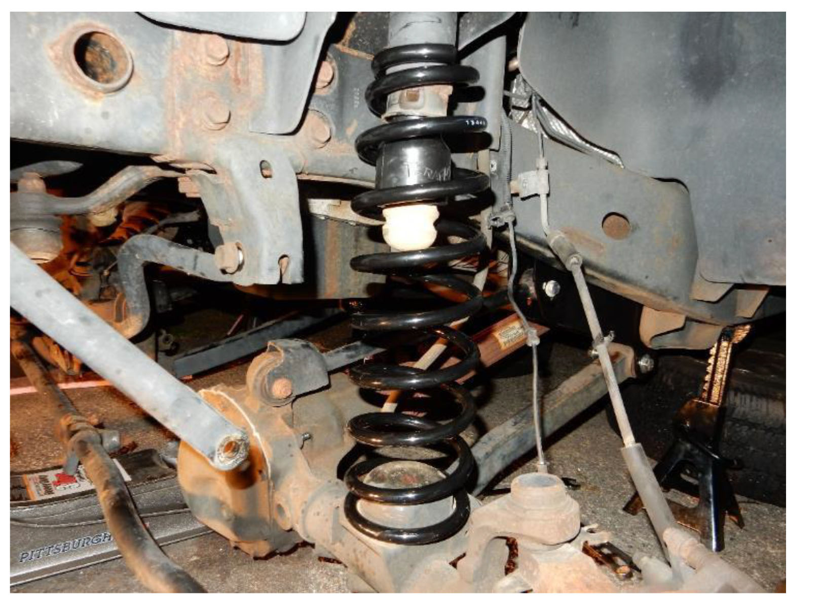
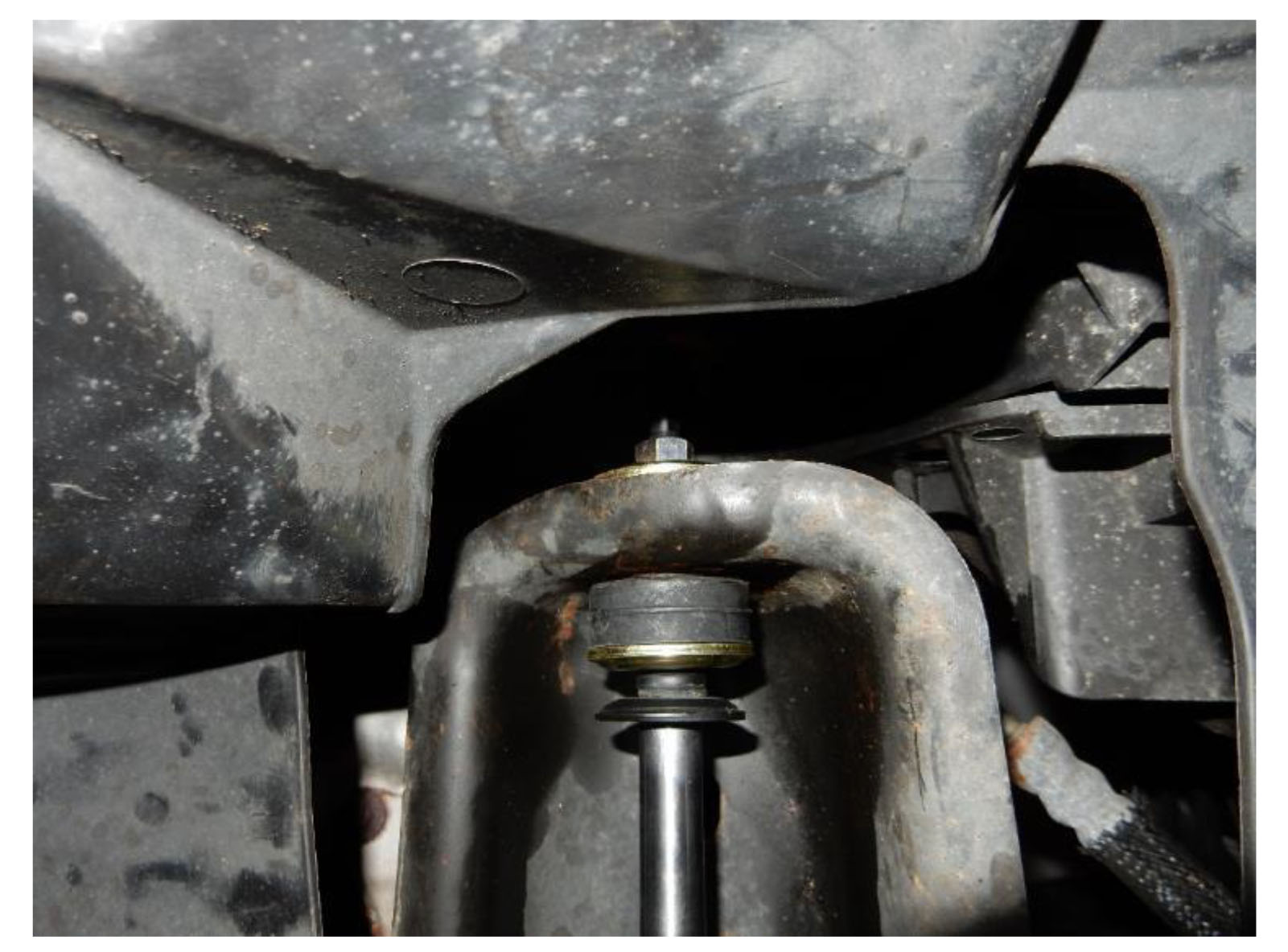
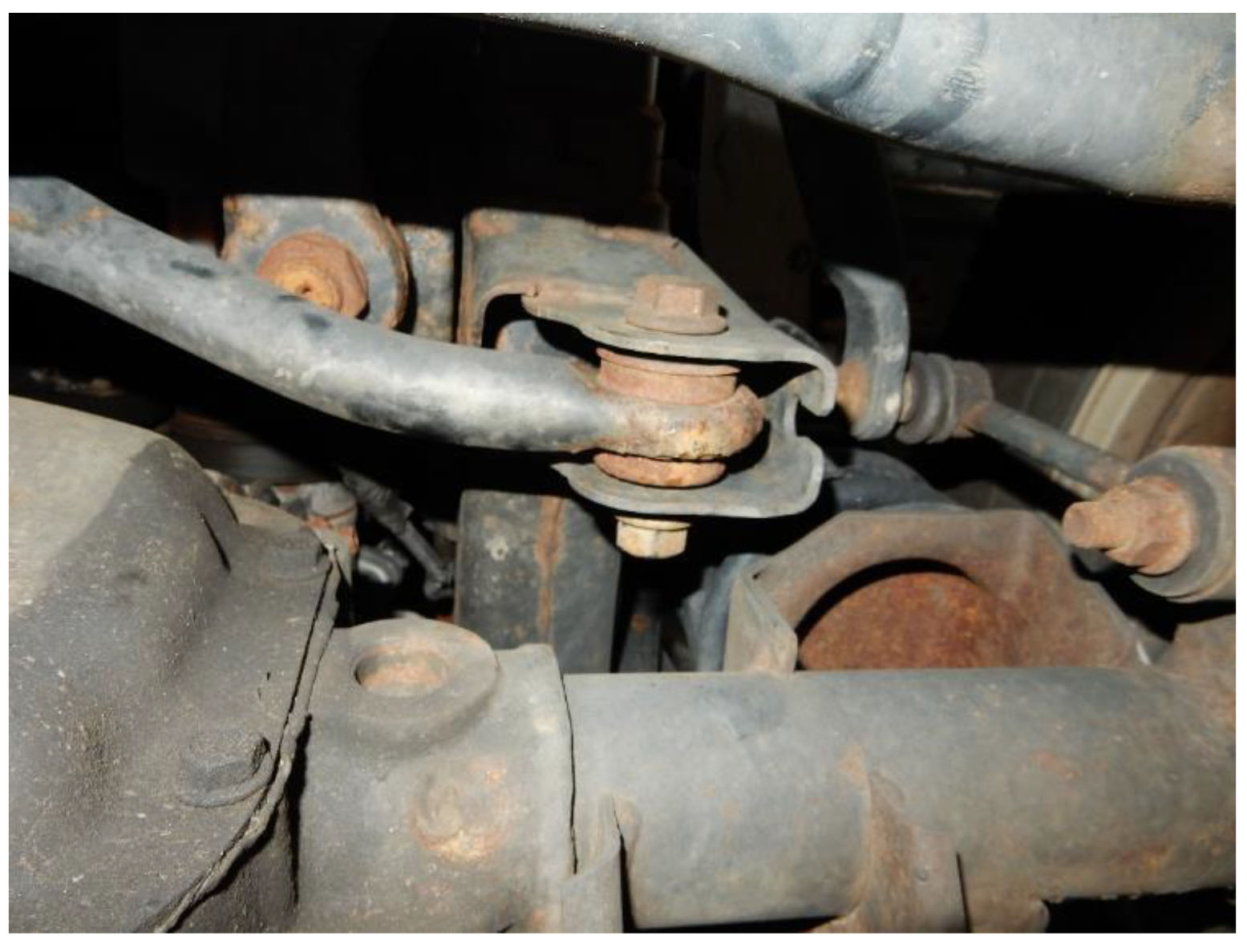
9. Using an 18mm socket and wrench, remove lower nut and bolt from the rear shocks on the driver and passenger sides.
10. Using a 16mm socket, remove upper bolts from rear shocks on the driver and passenger sides, remove the rear shocks.
Note: Apply penetrating oil to the bolts prior to removal, as captured nuts are utilized at these locations.
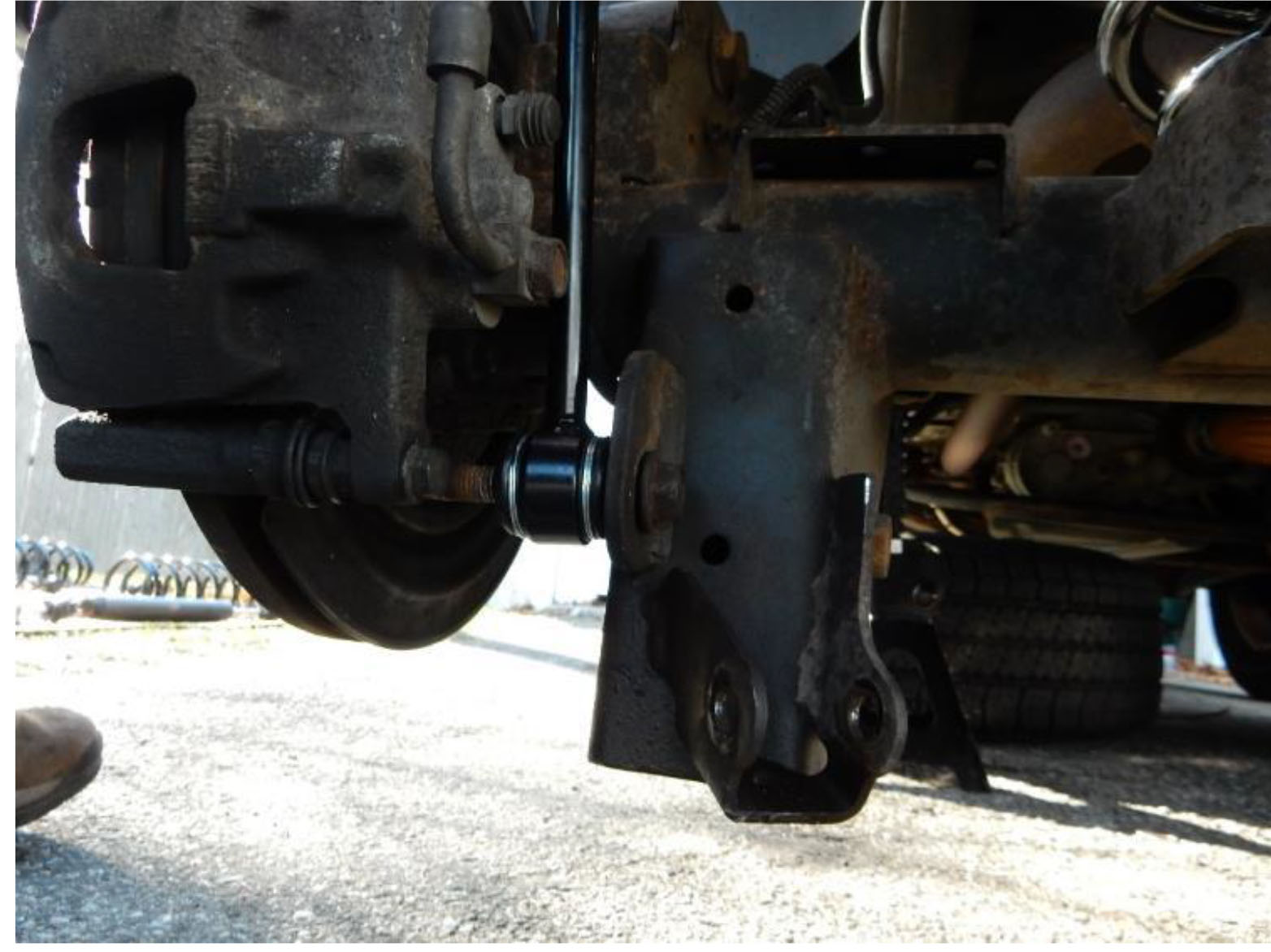
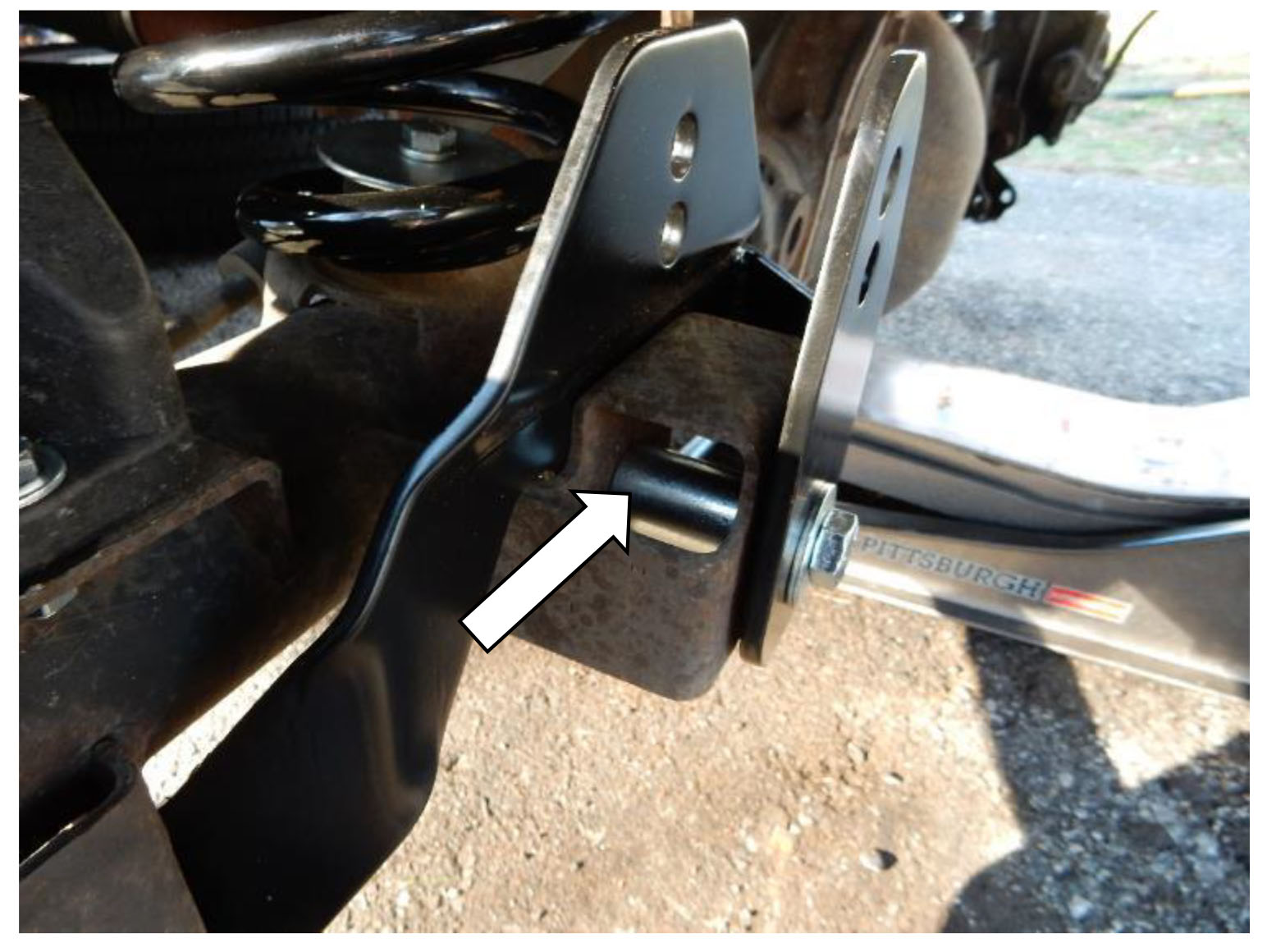
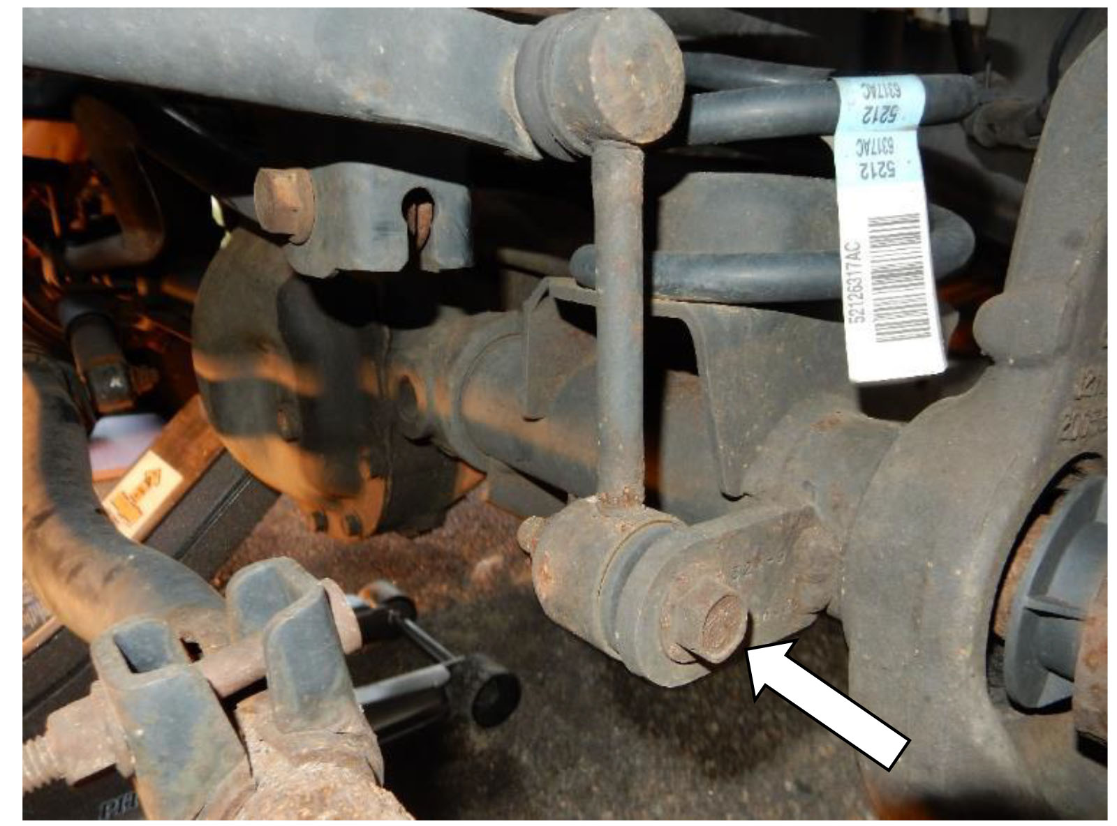
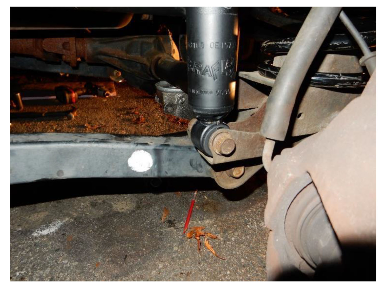
11. Using and 18mm socket and wrench, remove the bolt on the axle side of the rear sway bar links on the driver and passenger sides.
12. Using an 18mm socket, and a 19mm wrench to keep the stud opposite the nut from spinning, remove the nut from the sway bar side of the sway bar link on the driver and passenger sides. Remove sway bar links.
Note: Set factory sway bar links aside to be reused during front lift installation
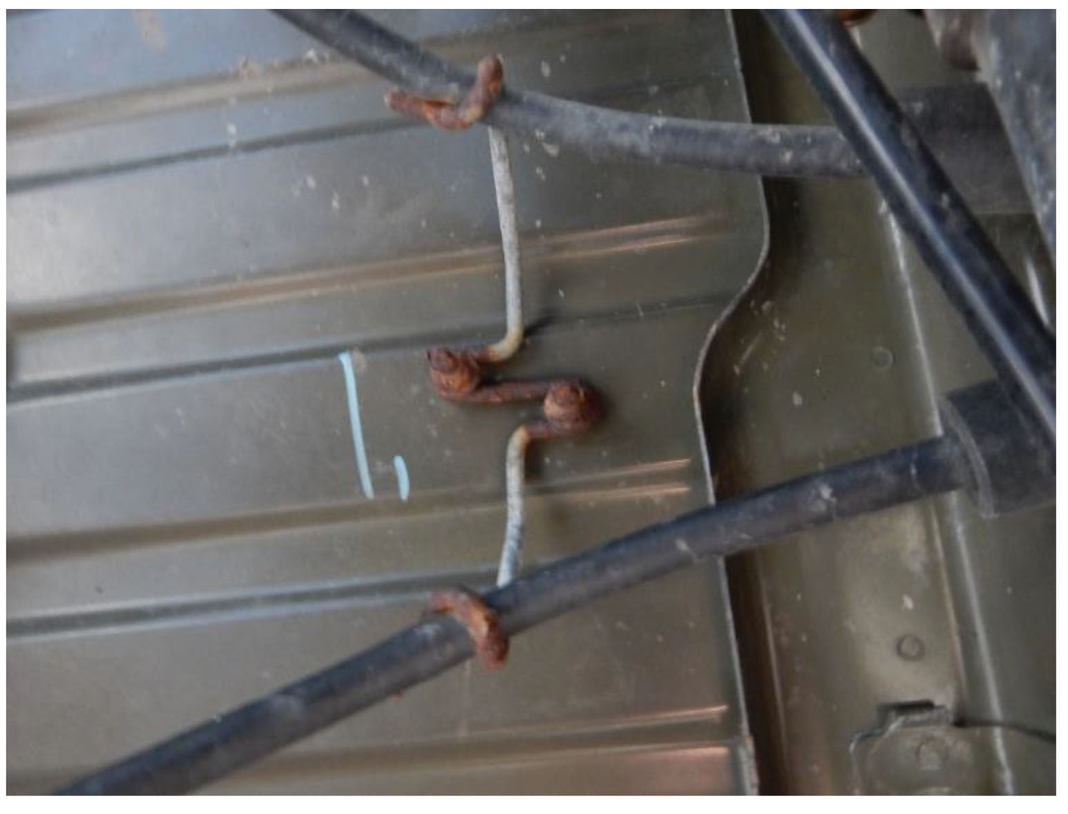
13. Cut or remove the clips securing the ABS wiring harness to the upper control arm mounts.
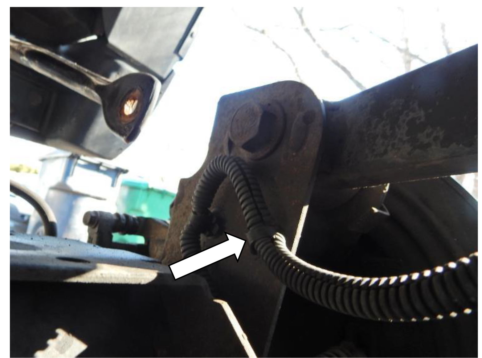
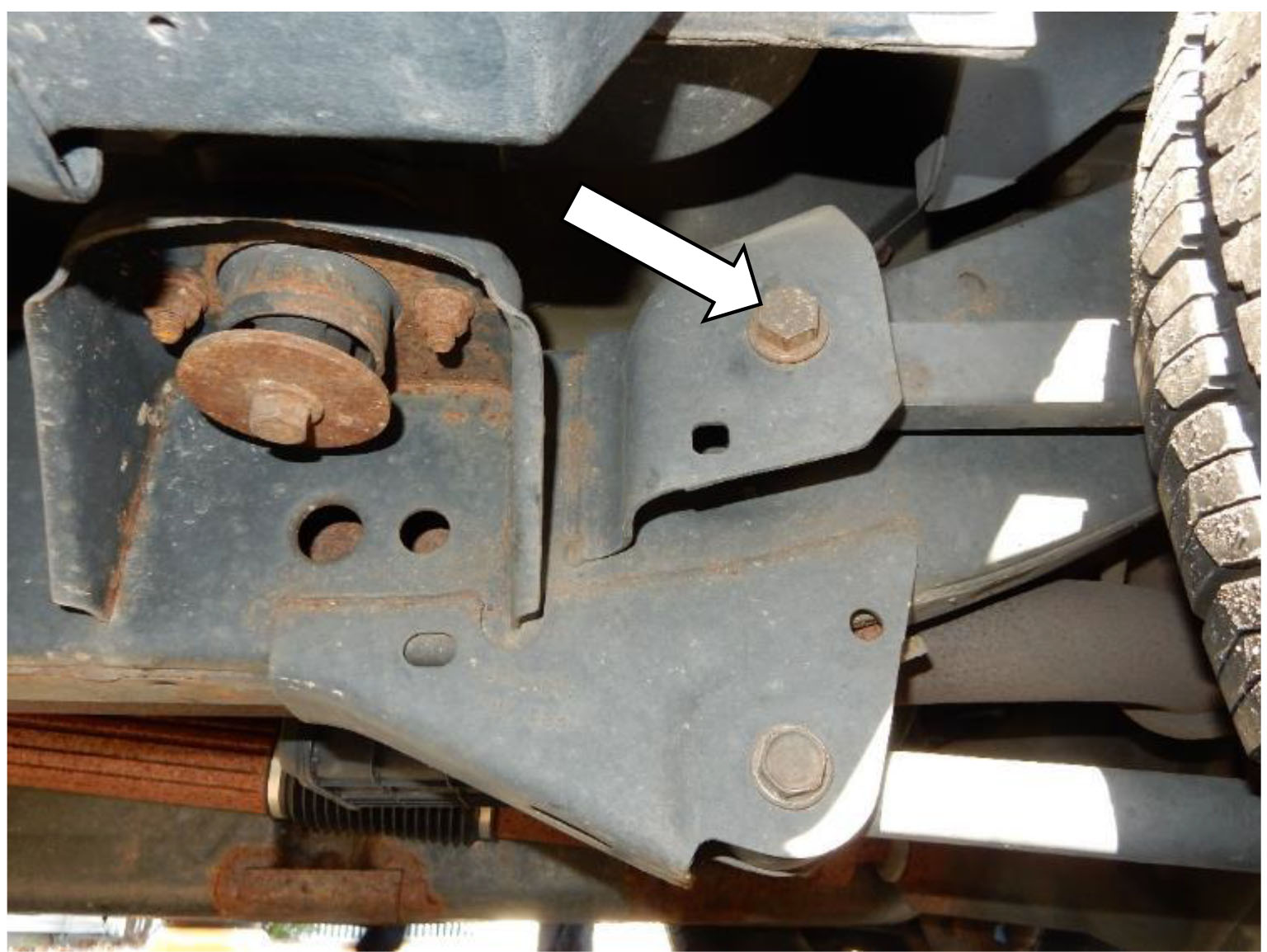
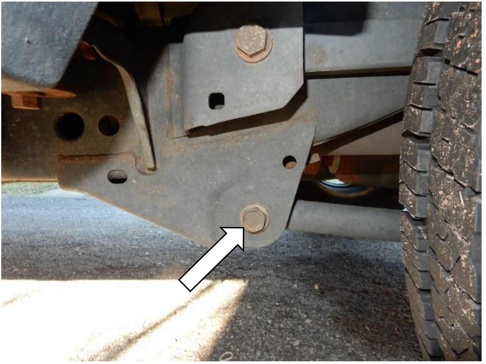
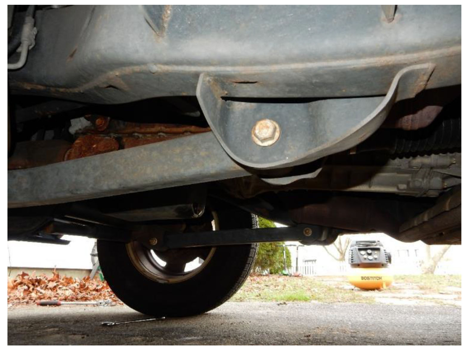
14. Using a 10mm socket, remove and discard the parking brake cable bracket from the underside of the body.
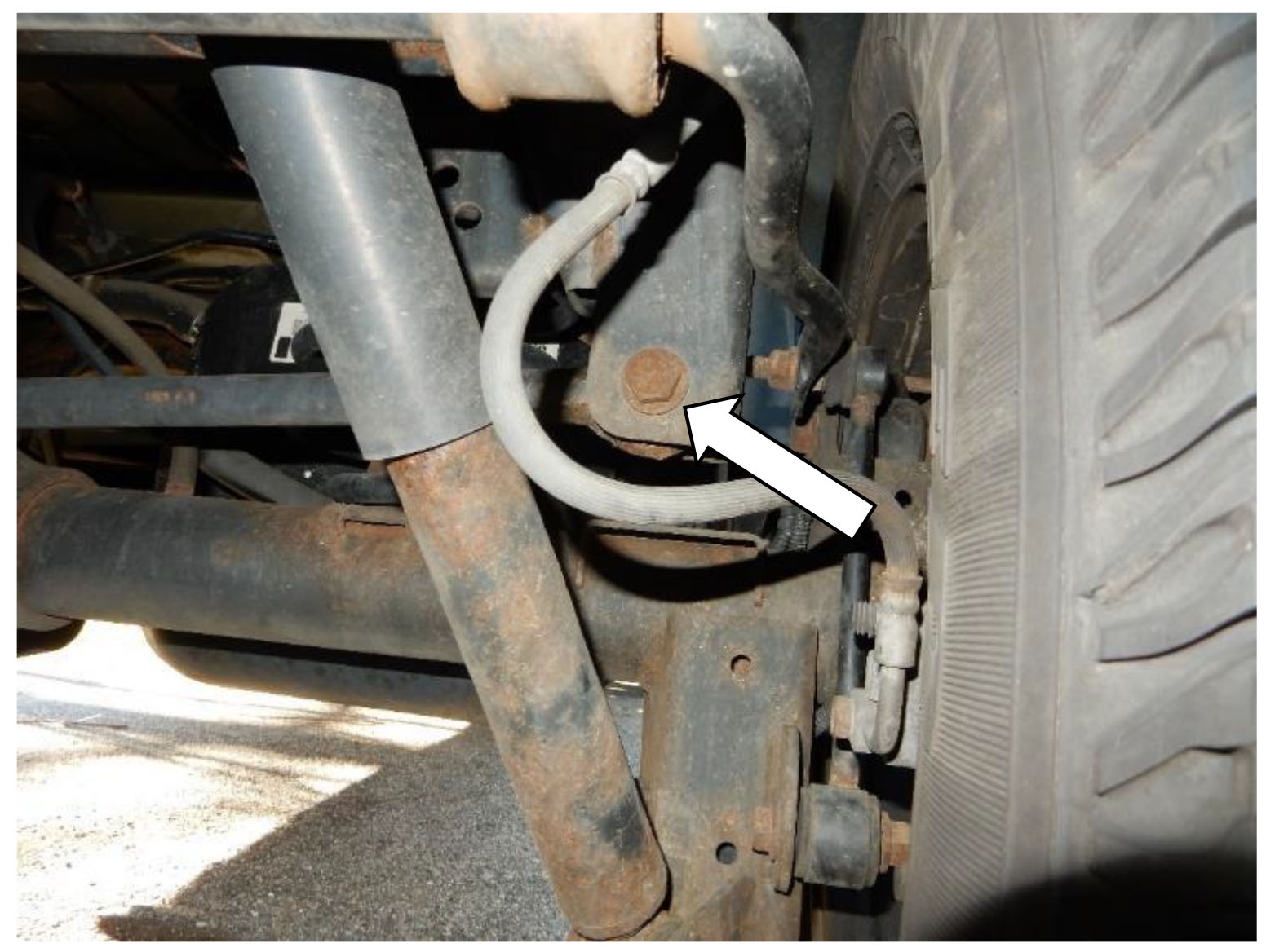
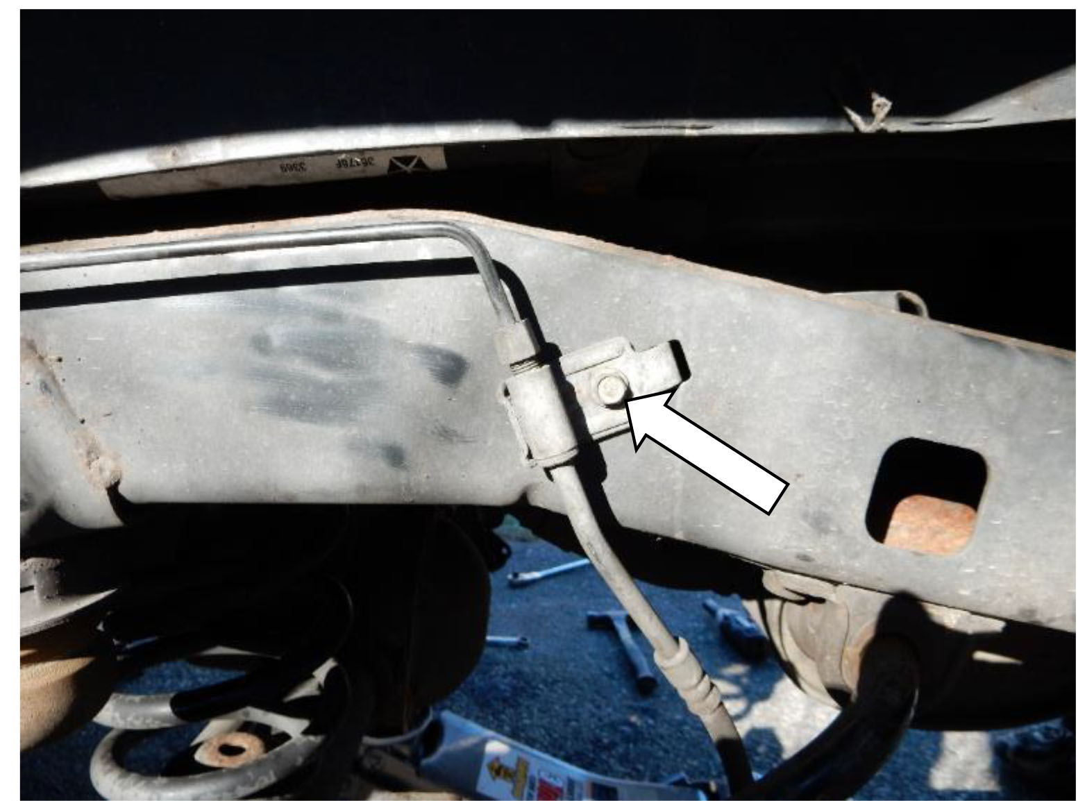
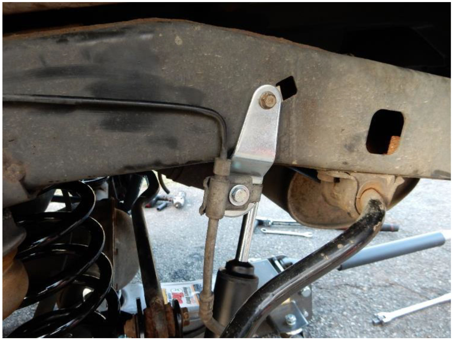
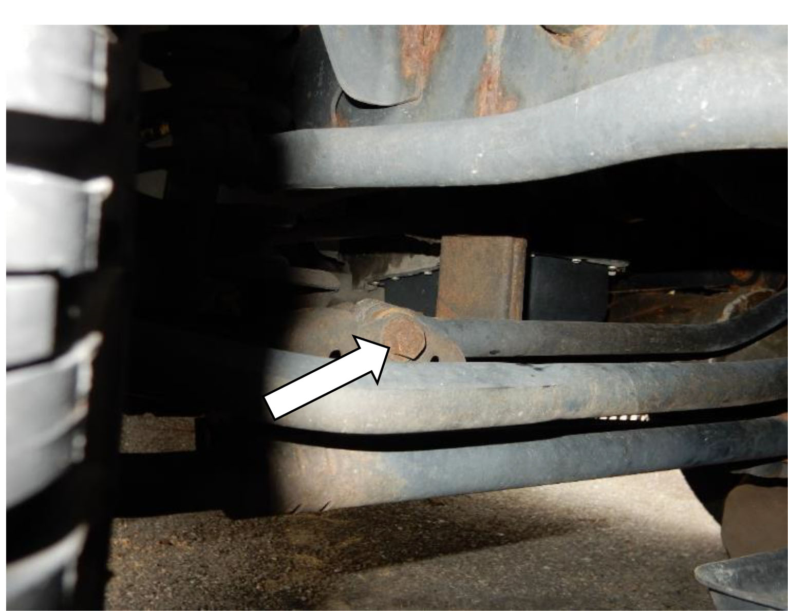
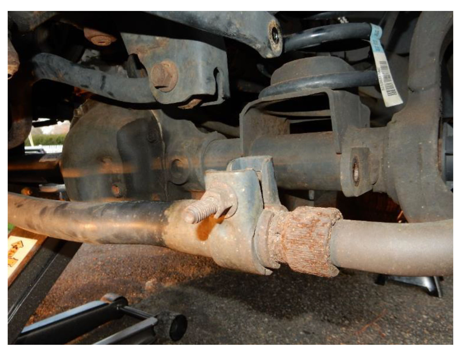
15. Using a 10mm socket, remove the bolt attaching the brake line mounting bracket to the frame.
Note: Do not remove the bracket from the brake line.
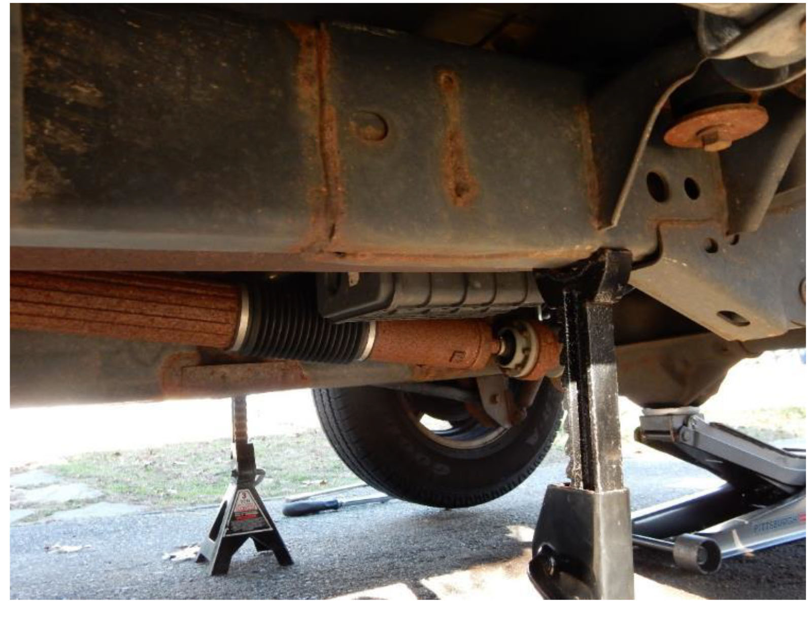
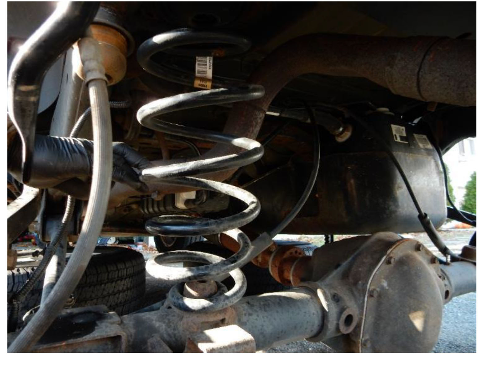
16. Using the floor jack, carefully lower the rear axle far enough to remove the springs from the driver and passenger sides.
Note: Be careful not to overextend the ABS, break lines, and breather tubes.
Note: Set factory spring isolator aside to be used with new springs.
17. Position the rear track bar into place at the frame, Using a 21mm socket and wrench reinstall the factory bolt and nut. Torque to 125 ft-lbs.
Note: Do not torque bolt until vehicle is on the ground and at ride height.
18. Install factory spring isolators onto the tops of the new springs.
Note: The tight wrapped coil is the located at the bottom of the spring.
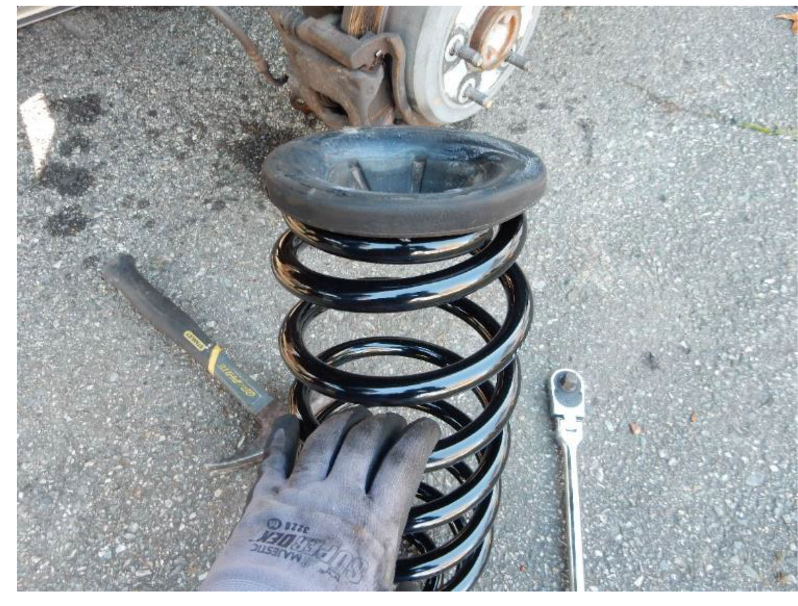
19. Install the new springs and isolators into position on the driver and passenger sides.
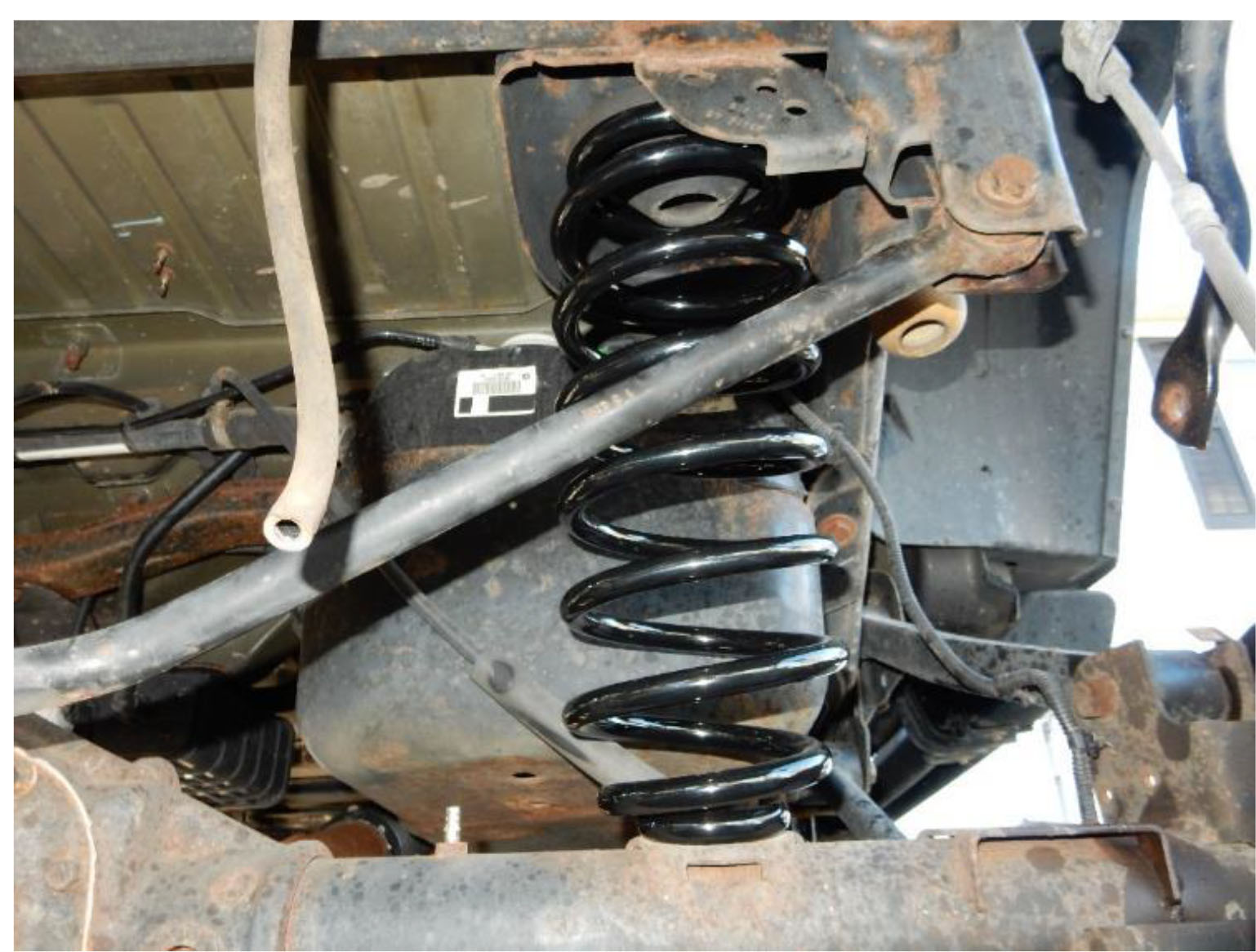
20. Using the floor jack, raise the rear axle just high enough to put pressure on the springs and hold them in place.
21. Install the spring retainer plates, on the driver and passenger sides, using a 14mm wrench on the bolt and the supplied wrench on the nut below the mount.
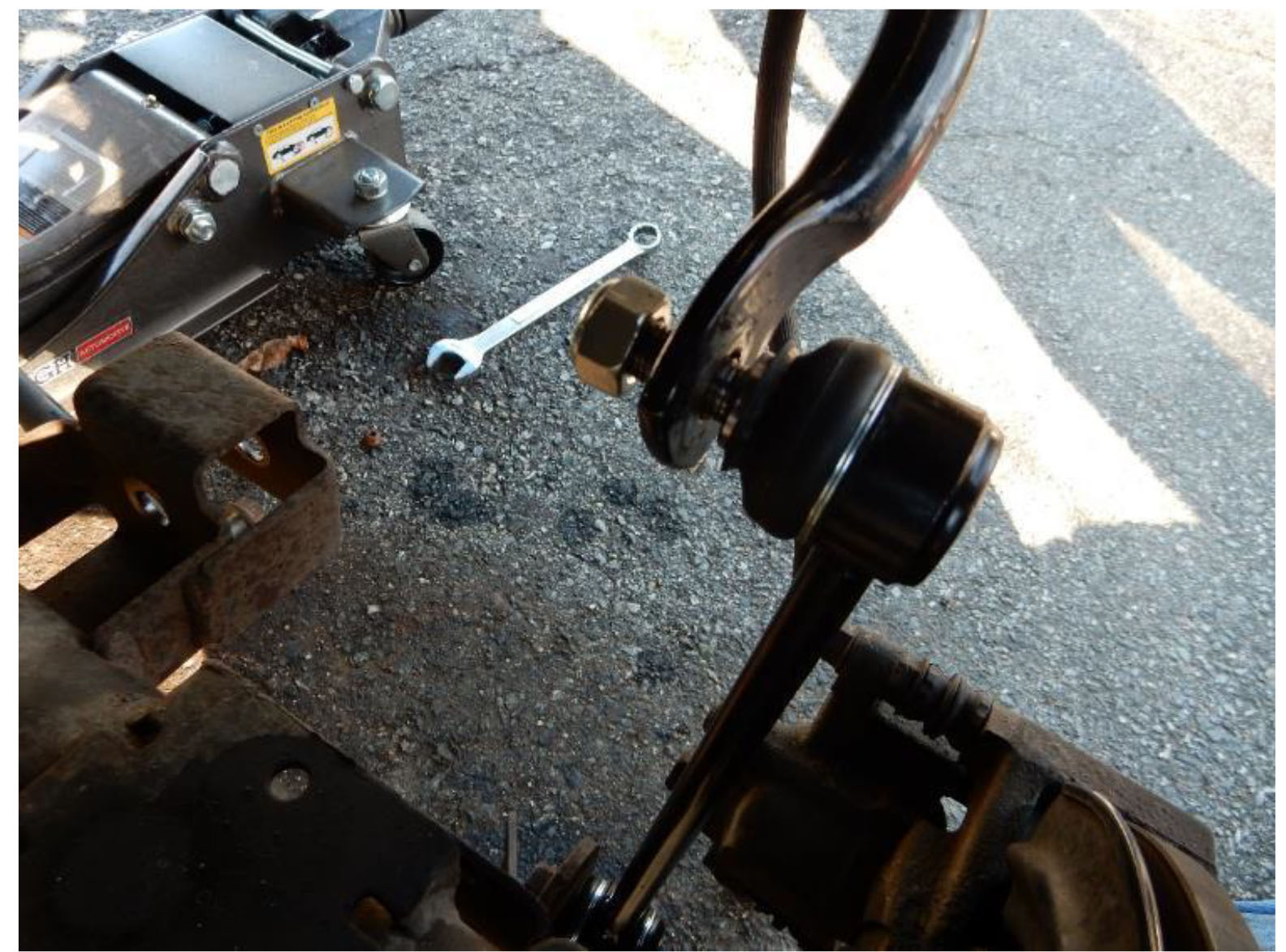
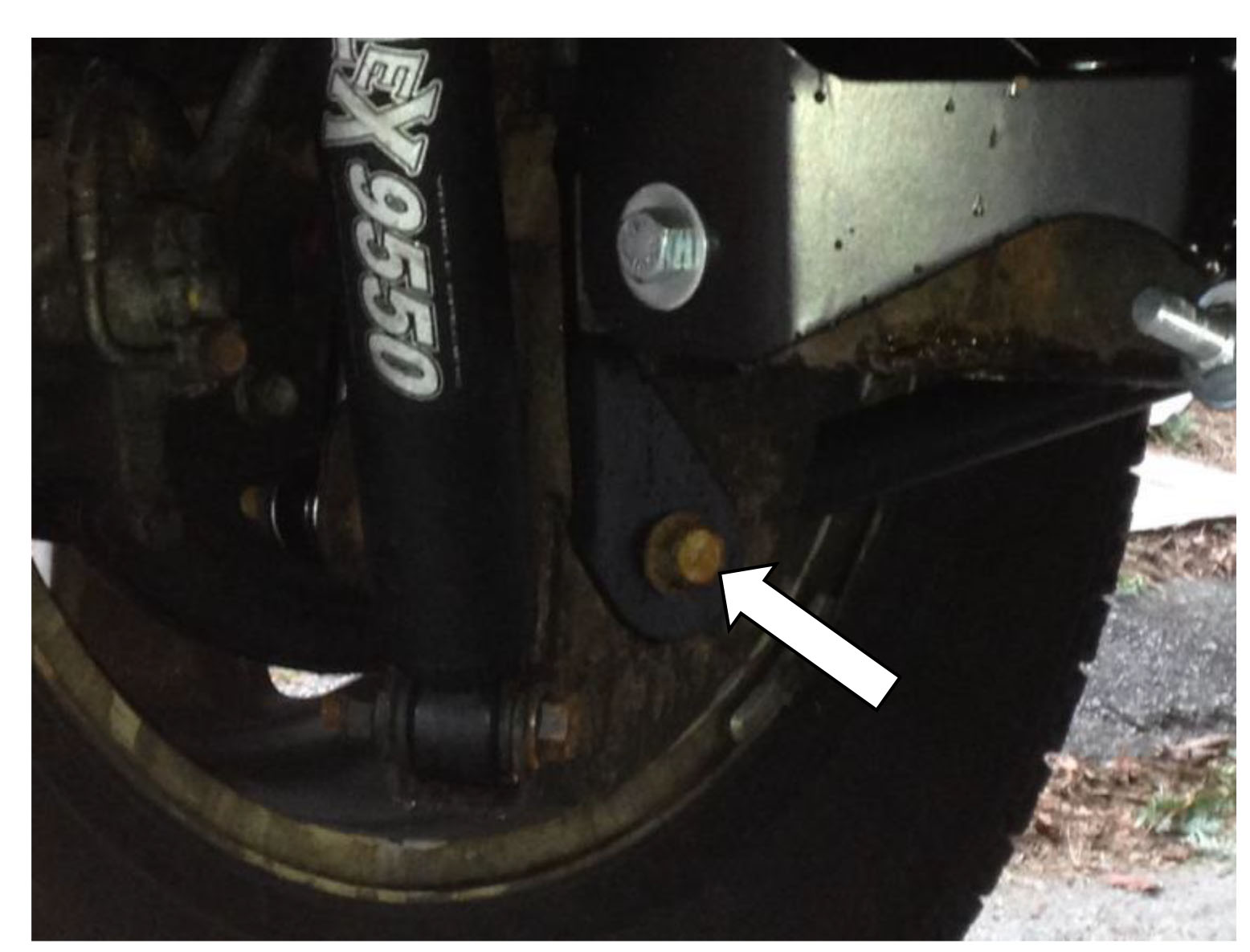
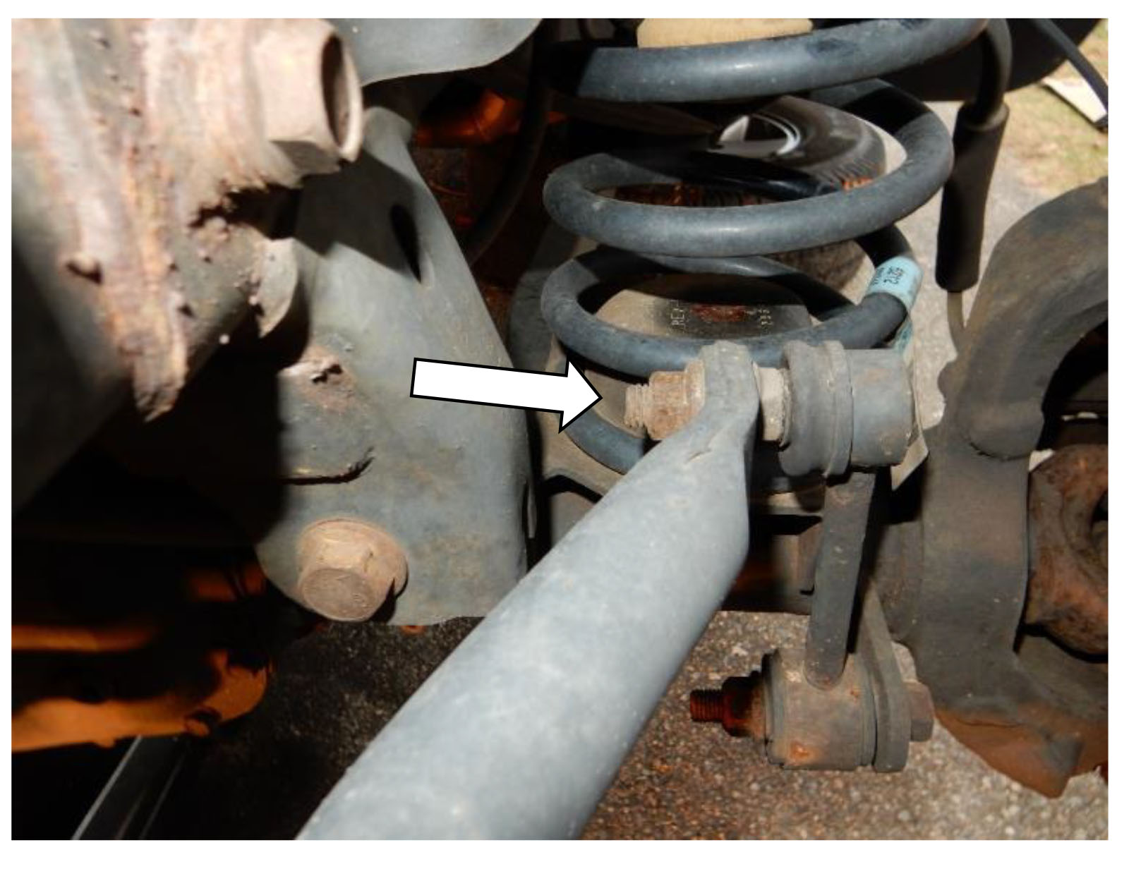
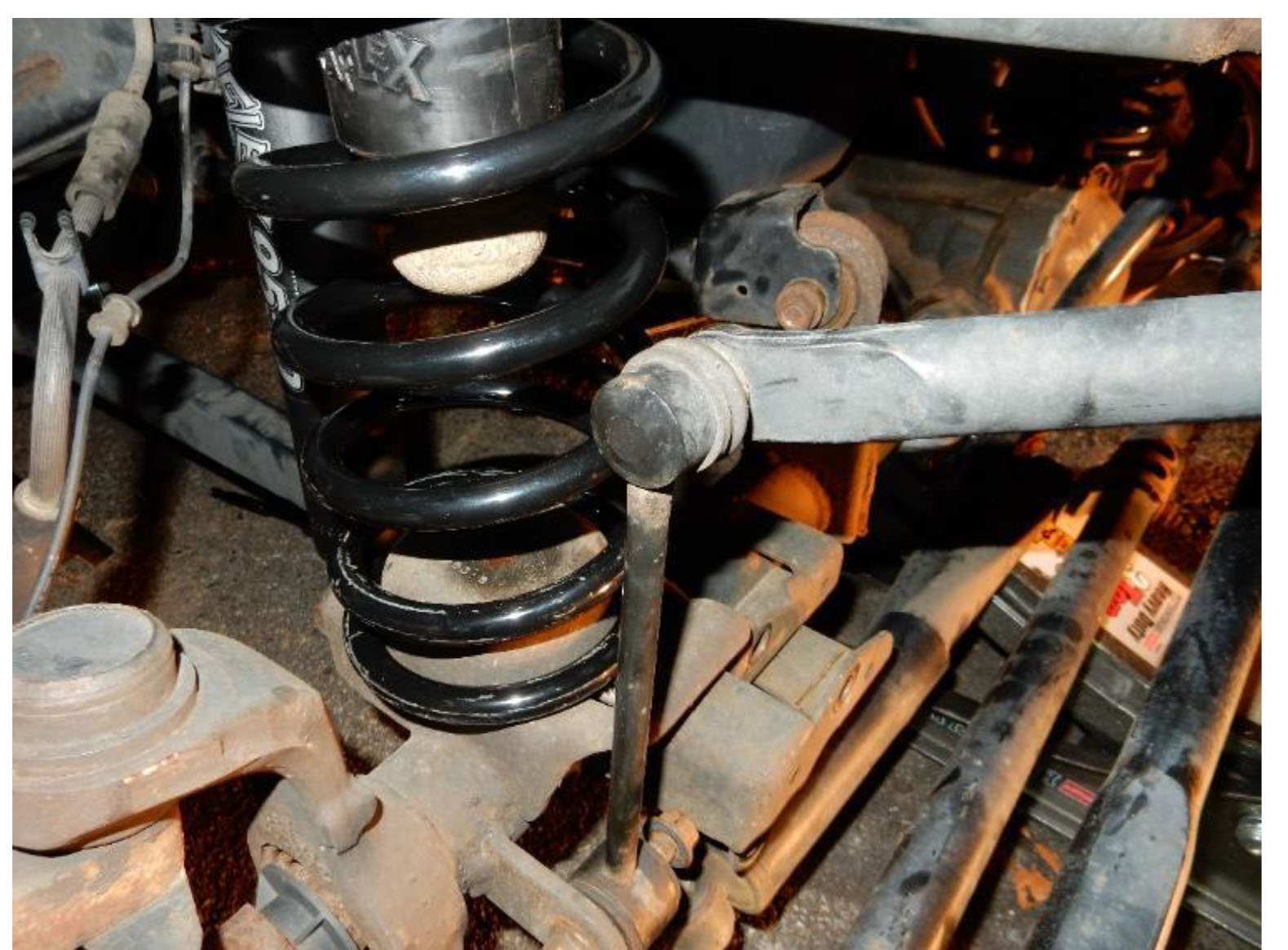
22. Using an 18mm socket and wrench, reinstall the factory bolt and nut to attach the axle side of the sway bar link to the axle bracket on the driver and passenger sides. Torque to 75 ft-lbs.
Note: The nut should be located on the outside to prevent interference with the shocks.
23. Using an 18mm socket and wrench, install provided 1/2”x20 bolt and washer and the 19mm nut and washer to attach the sway bar link to the sway bar on the driver and passenger sides. Torque to 75 ft-lbs.
Note: The nut should be located on the inside to prevent interference with the tires.
24. Position the lower bumpstop into place on the frame, aligning the mounting holes with the existing holes on the frame of the vehicle.
Note: The overhang portion of the bumpstop should face the front of the vehicle.
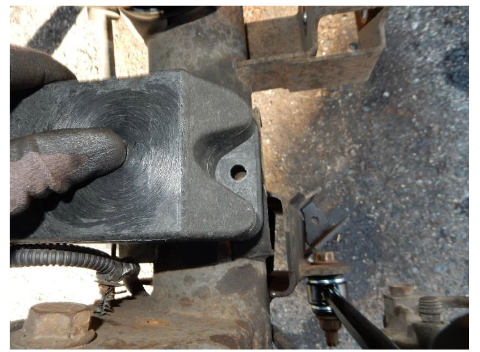
25. Using a 13mm socket and wrench, install provided bolts, nuts, and washers to attach the lower bumpstop extension to the frame on the driver and passenger sides.
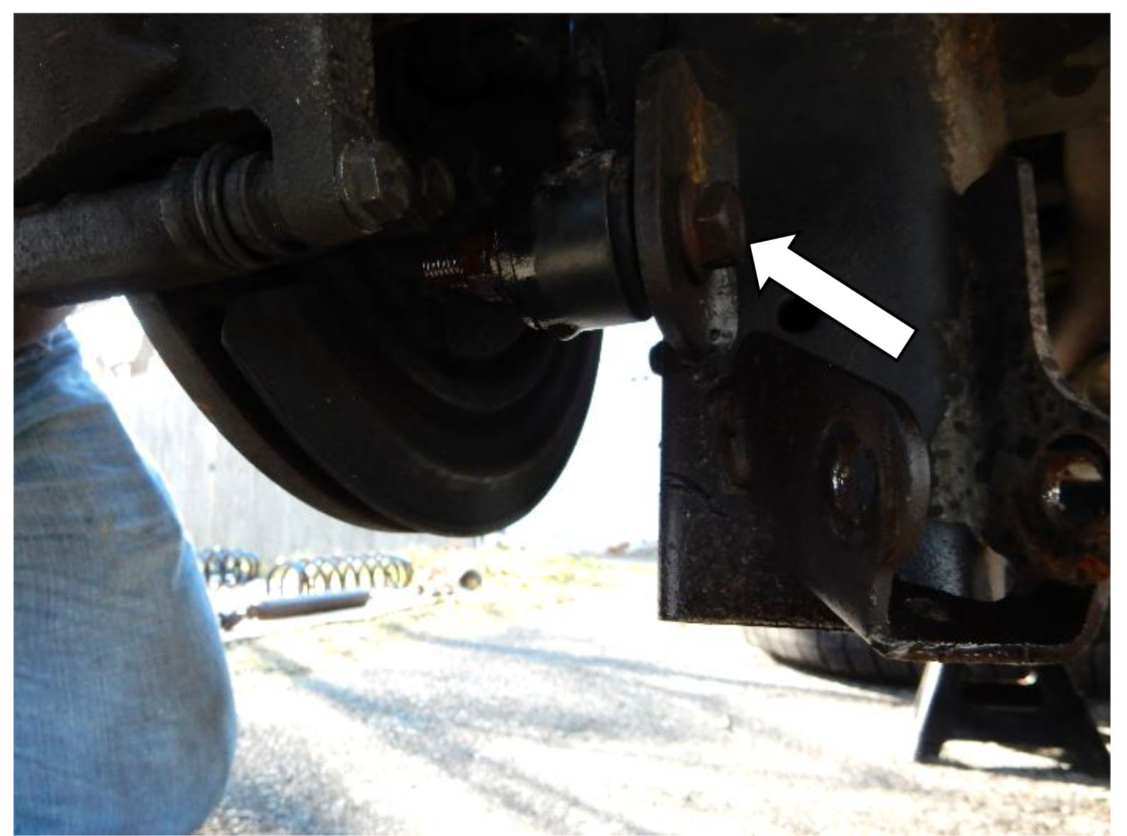
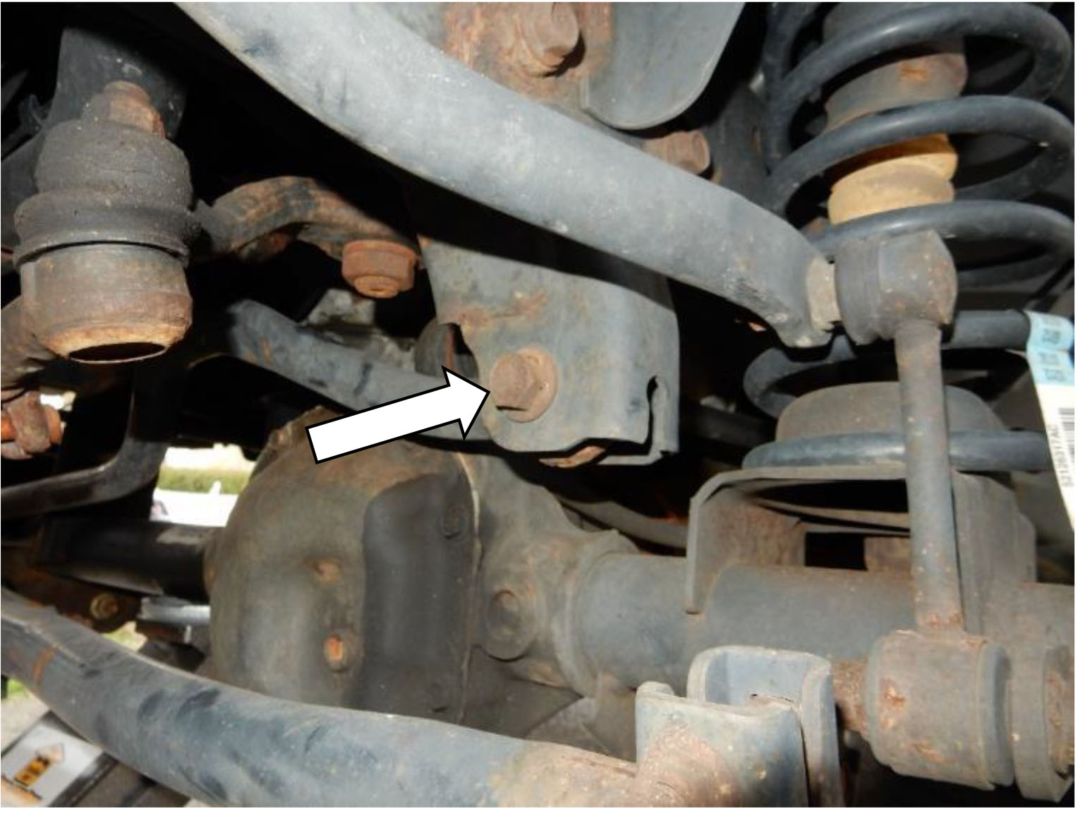
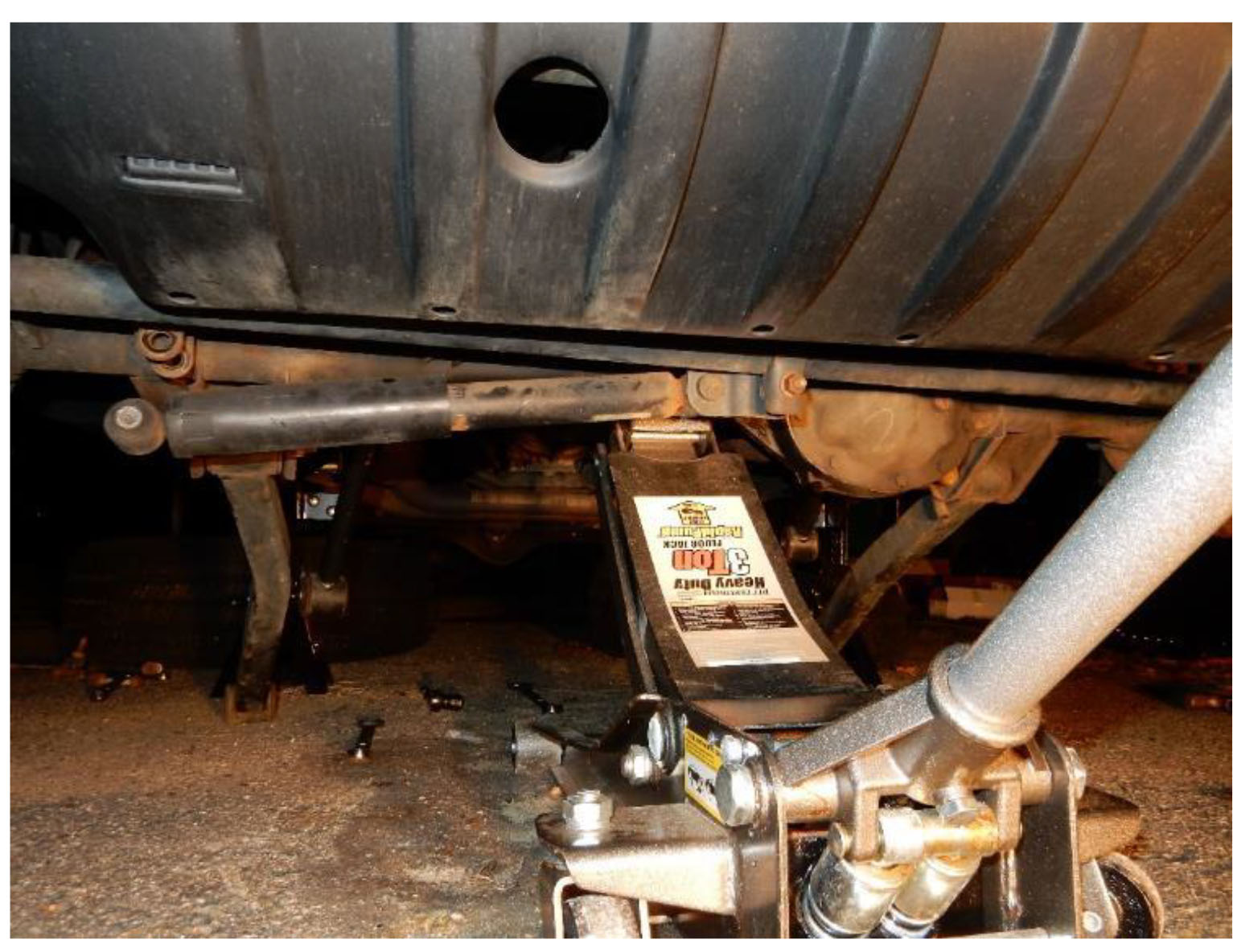
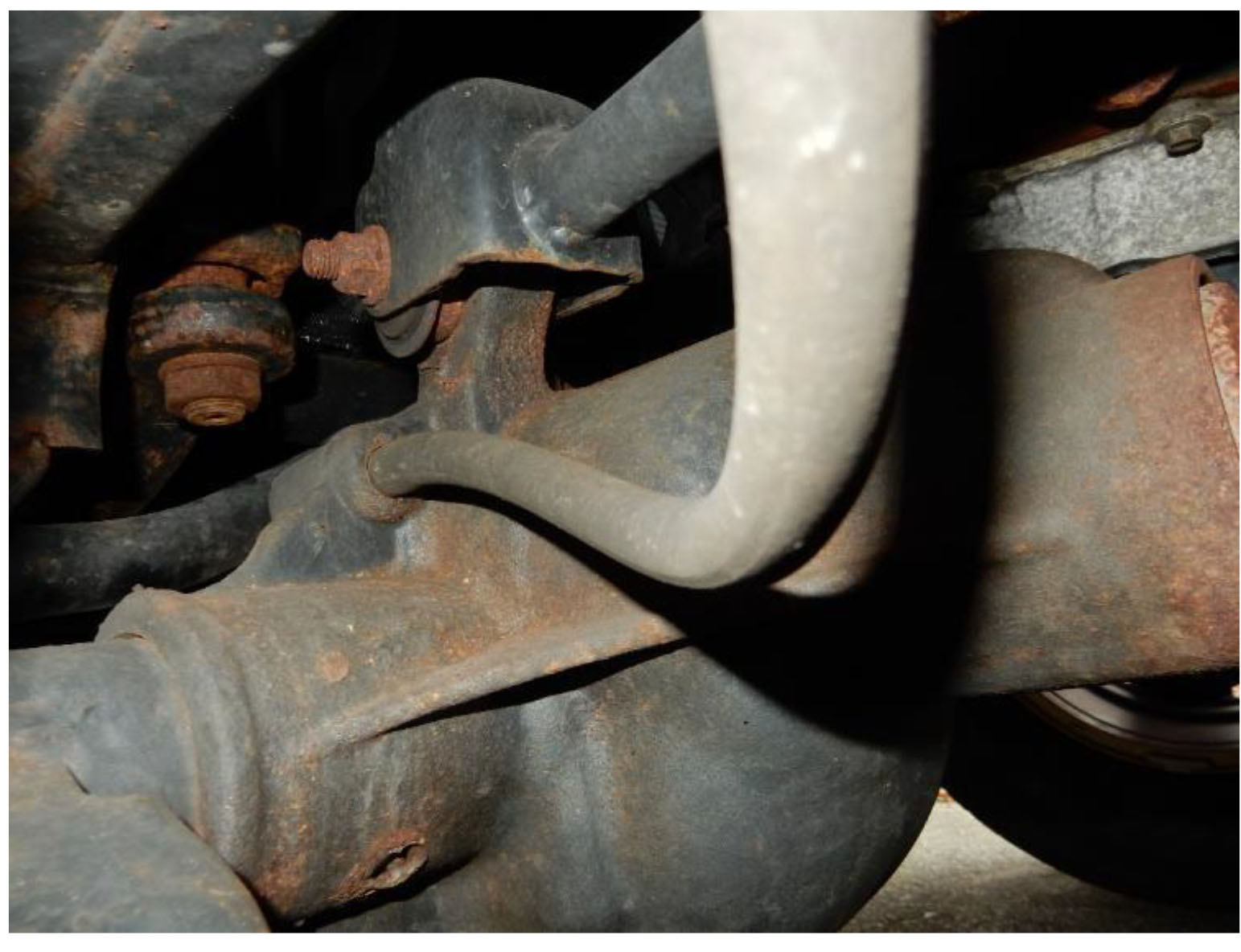
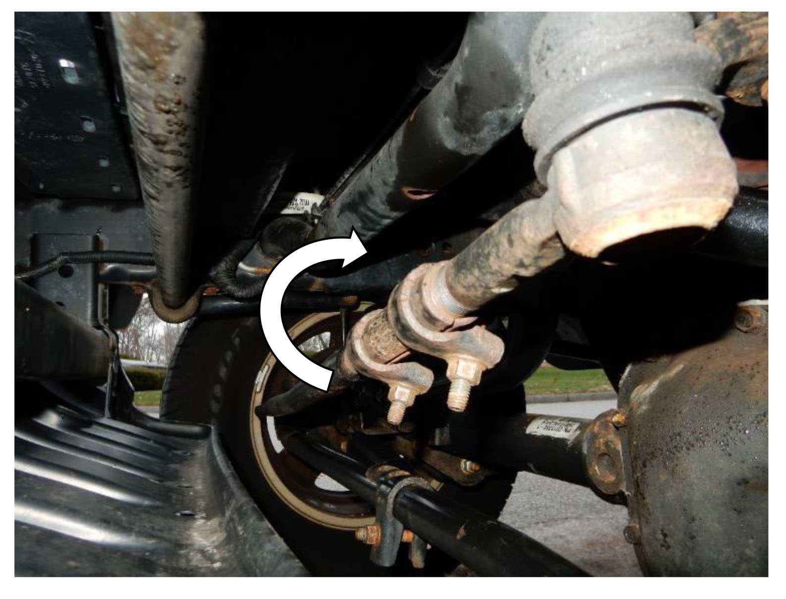
26. Using a 21mm Socket and wrench, remove the lower control arm axle side bolt.
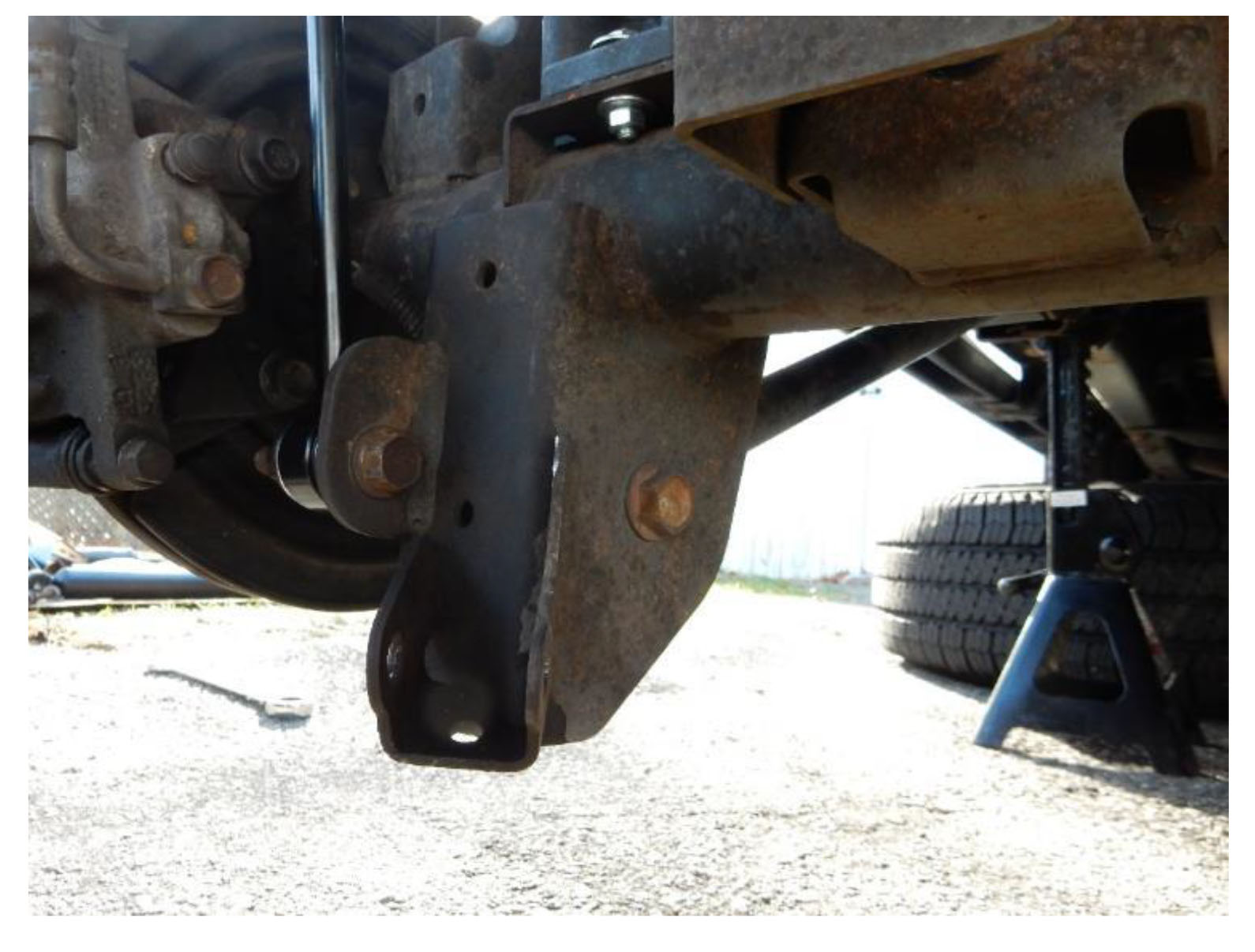
27. Position the rear axle track bar bracket over the factory track bar bracket, aligning the lower control arm bolt holes.
28. Using a 21 mm socket and wrench reinstall the lower control arm bolt. Torque to 125 ft-lbs.
Note: Do not torque bolt until vehicle is on the ground and at ride height.
29. Position the provided spacer sleeve between the factory track bar bracket and the axle track bar bracket. Using a 1/2” socket and wrench, install the provided 1/2”x3.5” bracket bolt, washers, and locknut to attach the axle track bar bracket to the factory track bar bracket. Torque to 75 ft-lbs.
Note: Do not torque bolts until all bolts are installed in the bracket.
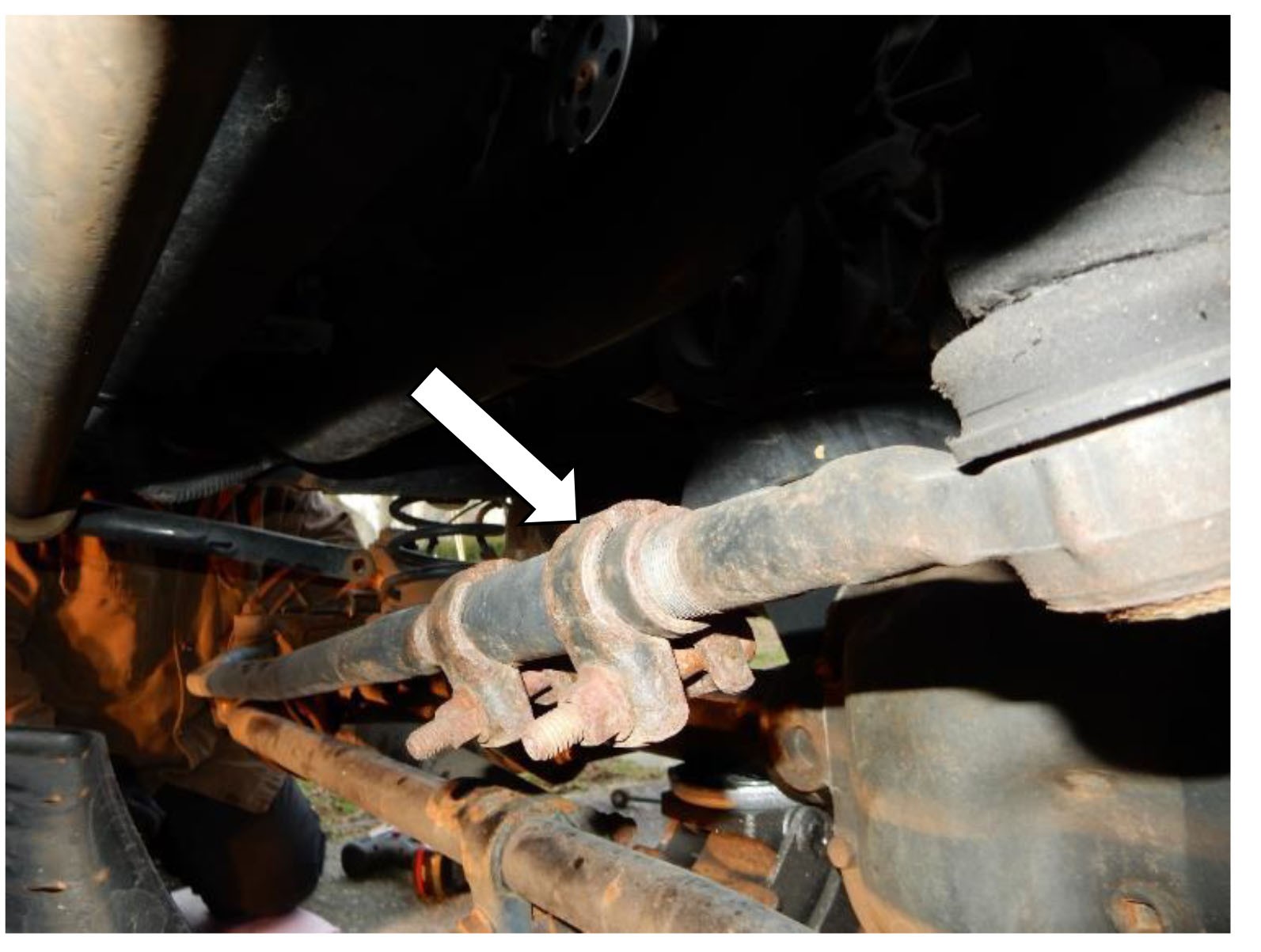
30. Position the provided U-bolt around the axle and into the bracket. Using a mm socket, attach with the provided washers and nuts. Torque to 85 ft-lbs.
Note: Torque both nuts on the U-bolt evenly.
Note: Torque remaining bolts on the axle track bar bracket to specified ft-lbs.
Note: Do not torque control arm bolt until vehicle is on the ground and at ride height.
31. Position the track bar in place at the axle track bar bracket. Using a 21mm wrench and socket, reinstall the factory bolt and nut. Torque to 125 ft-lbs.
Note: Do not torque bolt until vehicle is on the ground and at ride height.
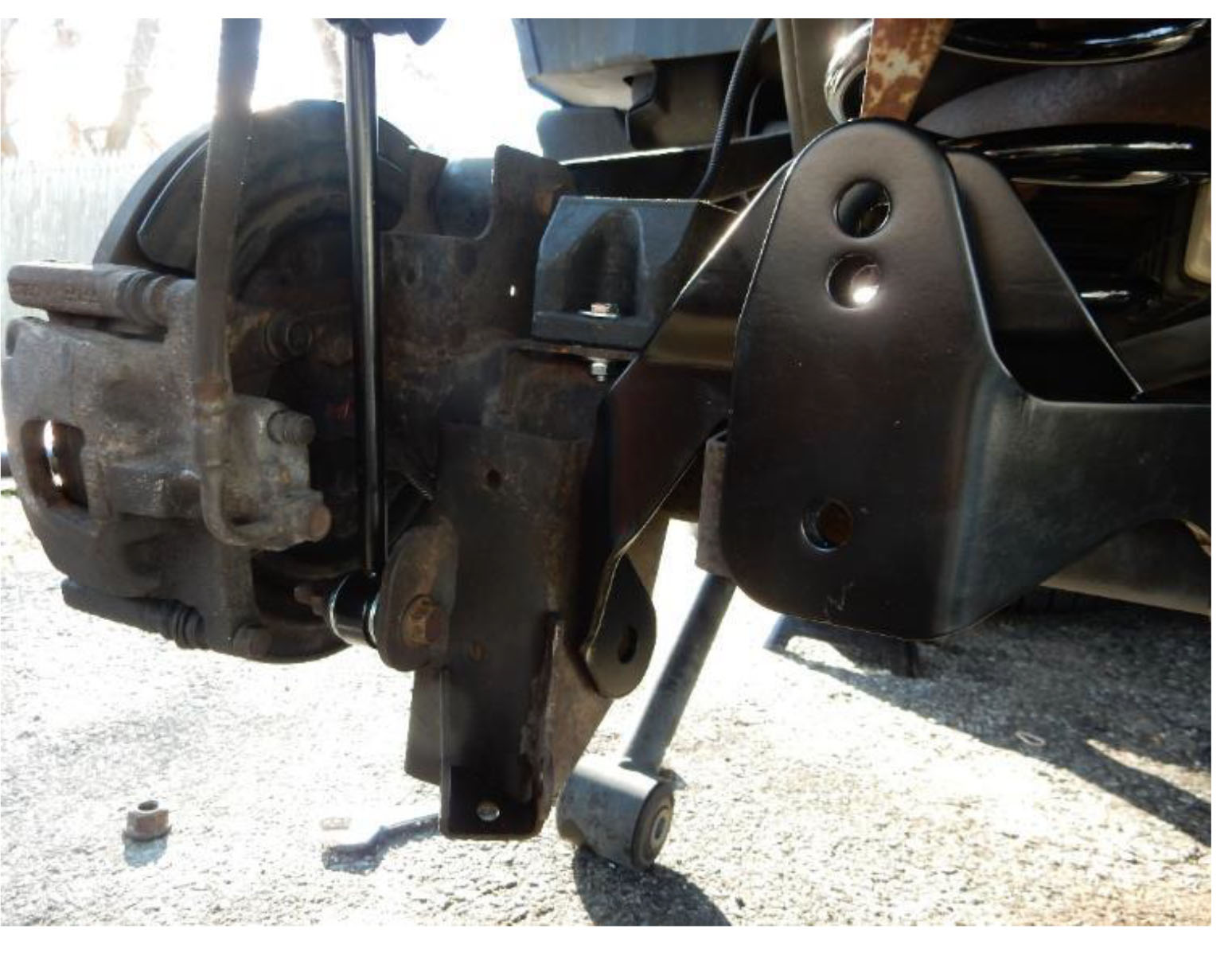
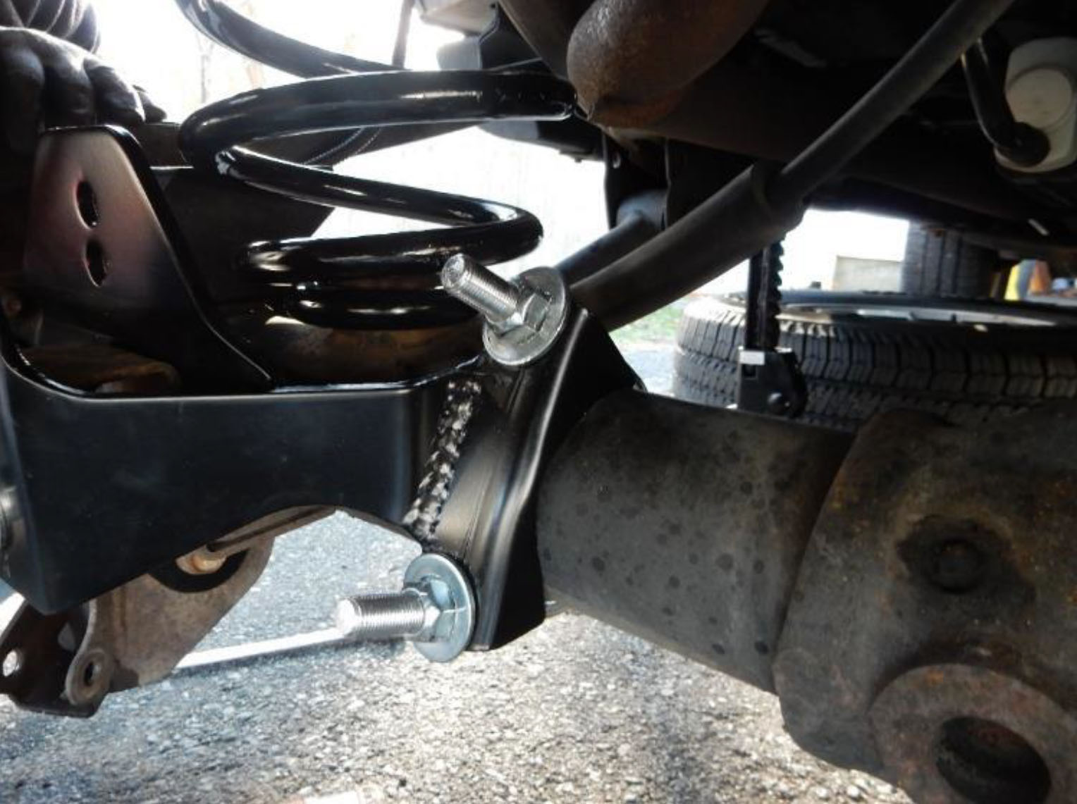
32. Position the new rear shocks in place, aligning the upper bolt holes. Using a 16mm socket, install the factory upper bolts to attach the rear shocks on the driver and passenger sides. Torque to 37 ft-lbs.
33. Position the new rear shocks in place, aligning the lower bolt holes. Using an 18mm socket and wrench, install the factory lower bolts and nuts to attach the rear shocks on the driver and passenger sides. Torque to 56 ft-lbs.
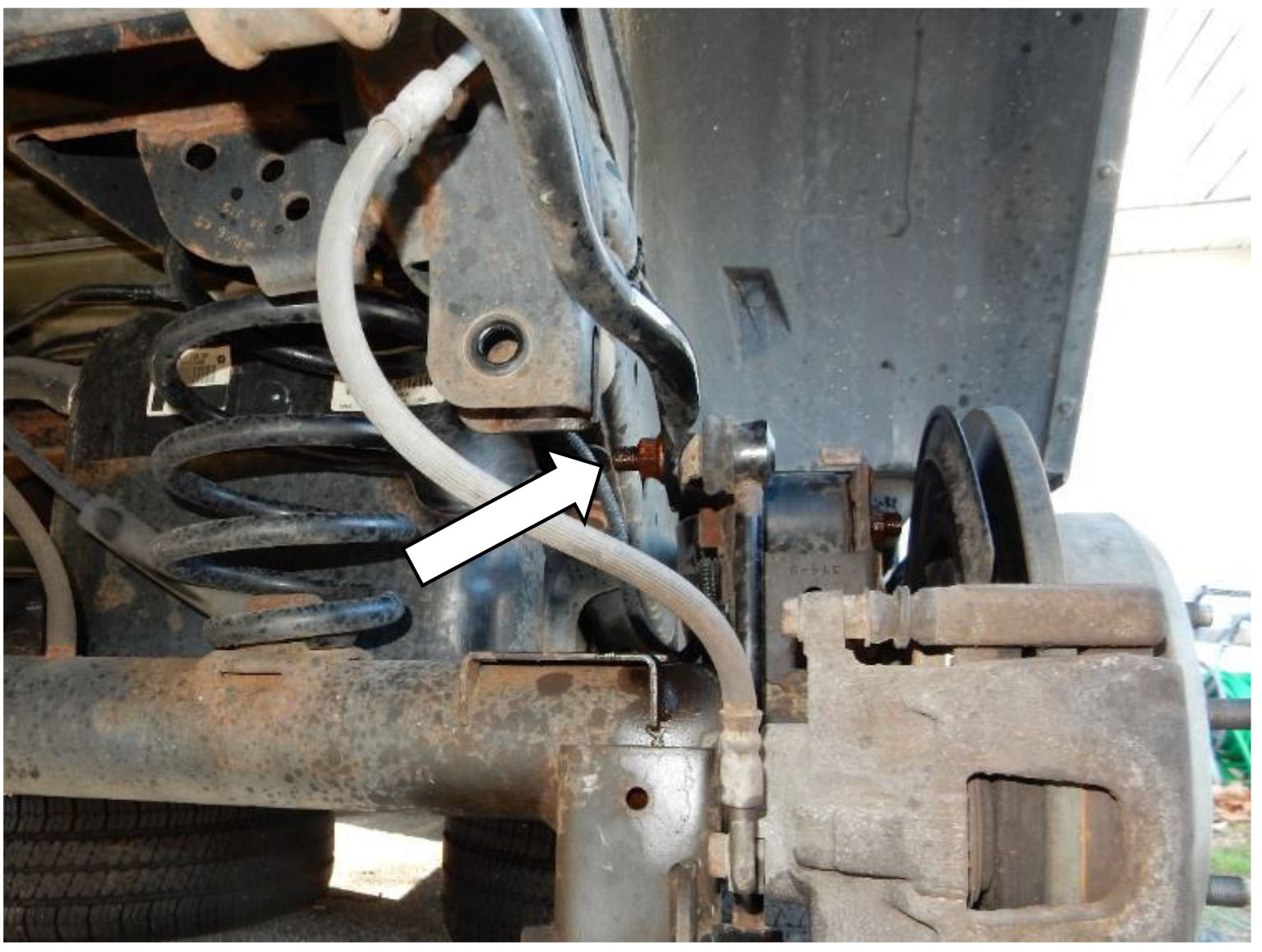
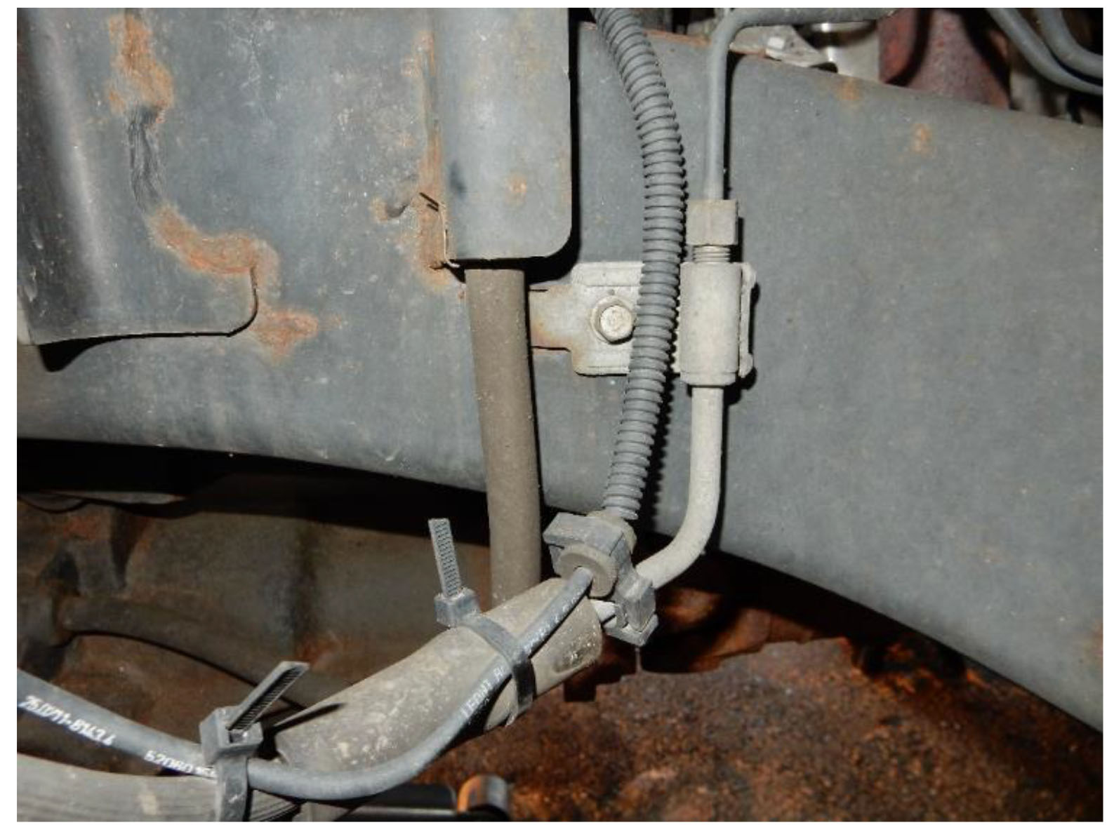
34. Position the rear brake line extension bracket in place, aligning the bolt hole with the hole in the frame where the factory bracket was attached. Using a 10mm socket, install the factory bolts to attach the bracket to the frame on the driver and passenger side.
Note: The bracket should bend inwards under the frame.
35. Using a 7/16” socket and wrench, install the supplied bolts, washers, and nuts to attach the factory brake line bracket to the brake line extension bracket on the driver and passenger sides. Torque to 120 inch-lbs.
Note: Check to make sure the hard brake line is against the frame to ensure that it doesn’t interfere with suspension movement. Adjust as required by pressing into place.
36. Reinstall tires. Using a 19mm socket reinstall lug nuts. Torque to 95-115 ft-lbs.
Note: Do not torque lug nuts until vehicle is on the ground.
37. Lower the vehicle to the ground.
Note: Remove the chock from the front tires after all bolts have been properly torqued.
38. Torque all control arm bolts to the specified settings.
39. Using a 21mm socket, remove the bolt connecting the front track bar to the axle bracket.
Note: A flag nut is used on this bolt.
40. Using a 21mm socket and wrench, remove the bolt connecting the front track bar to the frame, remove the front track bar.
41. Using a 21mm socket, loosen the bolts on the front upper control arm on the driver and passenger sides.
Note: DO NOT REMOVE THE BOLTS OR CONTROL ARMS
42. Using a 21mm socket, loosen the bolts on the front lower control arm on the driver and passenger sides.
Note: DO NOT REMOVE THE BOLTS OR CONTROL ARMS
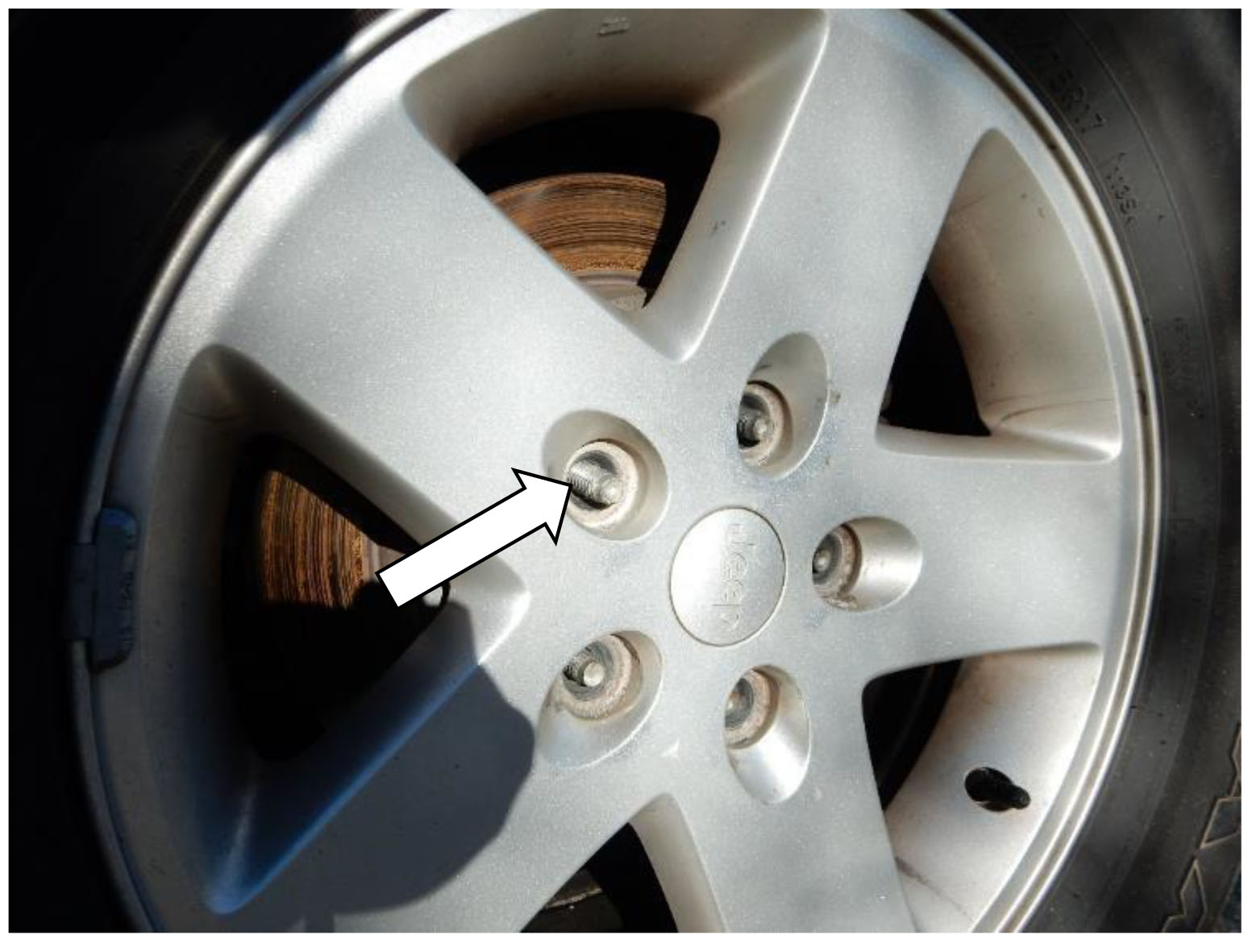
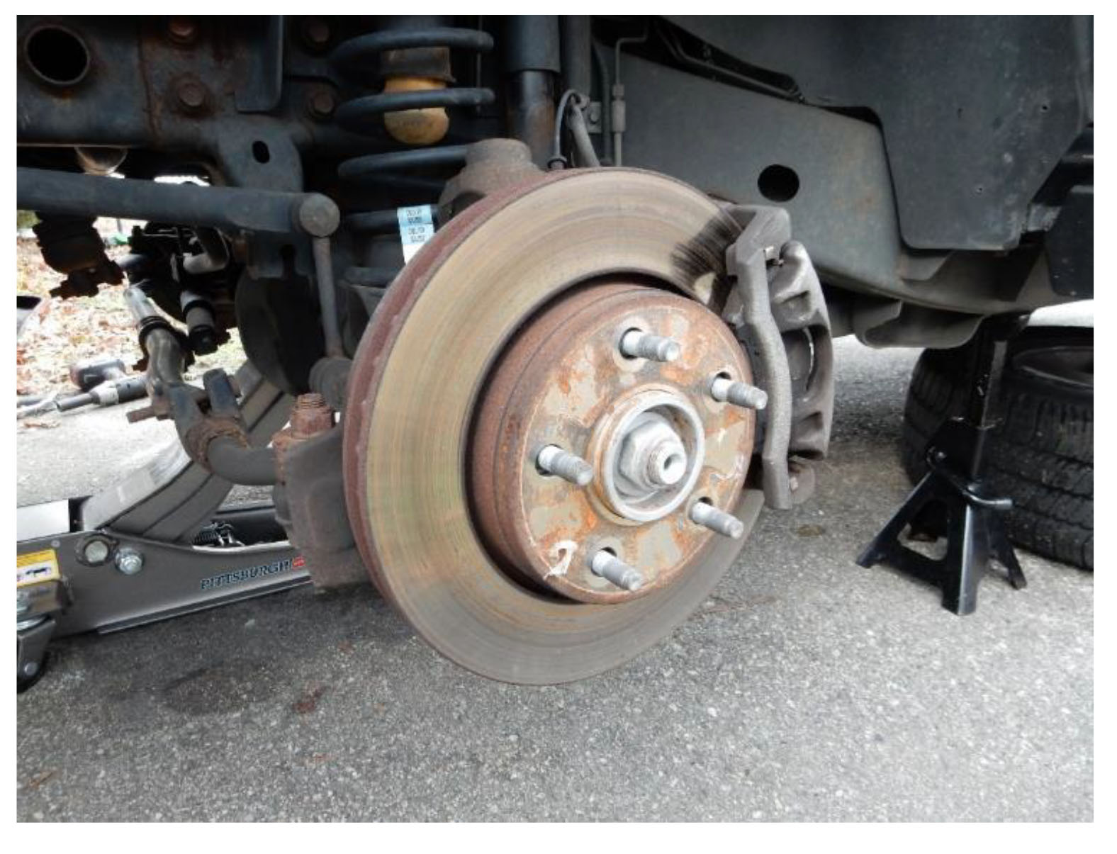
43. Using a 19mm socket, break loose the lug nuts on the front wheels, do not remove the nuts completely.
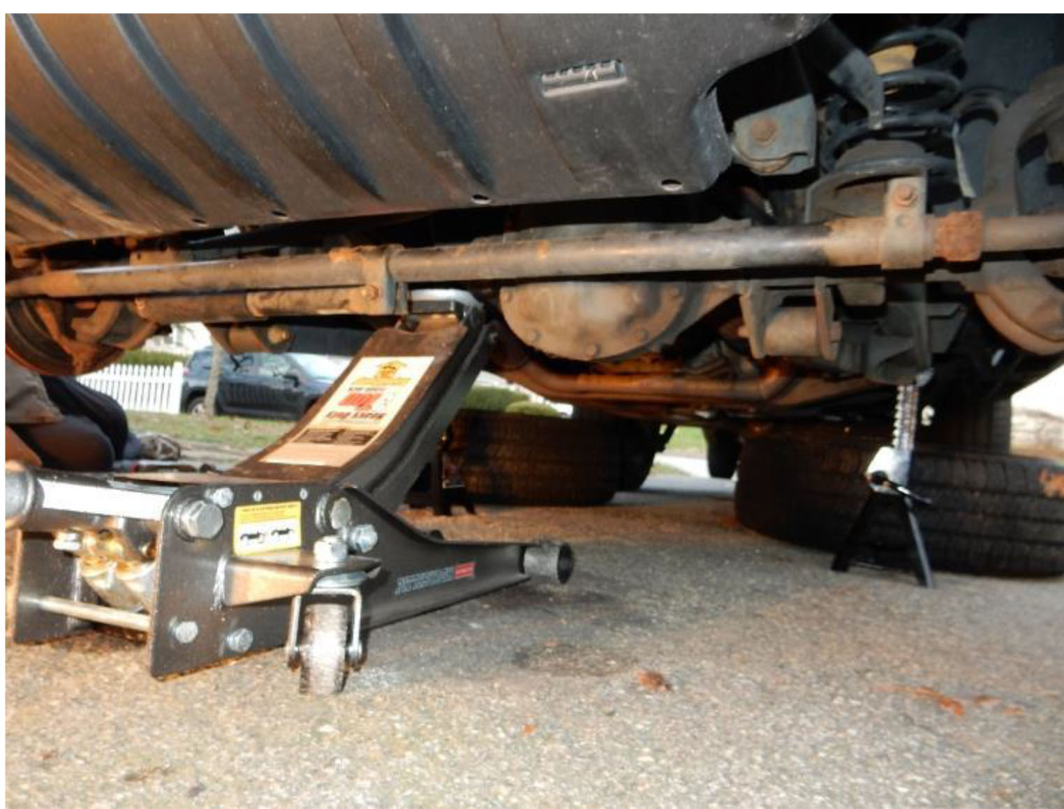
44. Using a floor jack, aligned under the front differential, lift the Jeep high enough to raise the front wheels off the ground.
45. Place jack stands under the frame, lower the floor jack until the vehicles weight is fully supported by the jack stands.
Note: Leave the floor jack under the front axle to be used later.
46. Using a 19mm socket, remove the lug nuts from the front wheels. Remove front wheels from the driver and passenger sides.
47. Using a floor jack, slightly raise the axle to make it easier to remove factory hardware.
48. Using an 18mm socket, remove the lower bolt from the front shocks on the driver and passenger sides.
49. Using a 16mm wrench, remove the upper nut from the front shocks on the driver and passenger sides.
Note: a 5/8” wrench can be used just below the shock mount to keep the shock from spinning.
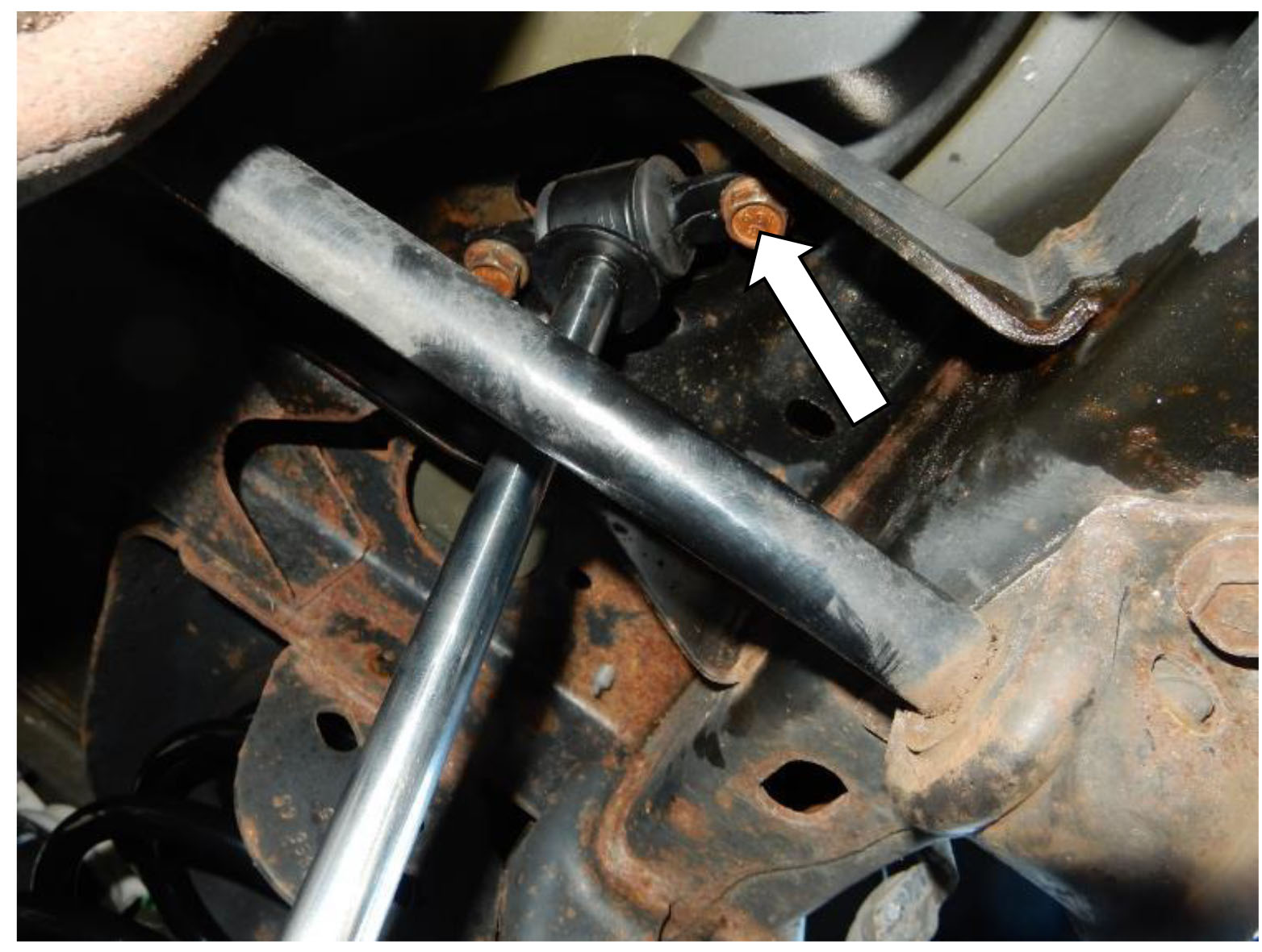
50. Using an 18mm socket and wrench, remove the lower bolt from the front sway bar links on the driver and passenger sides.
51. Using an 18mm socket and 19mm wrench, remove the upper bolt from the front sway bar links on the driver and passenger sides.
52. Cut or remove the clips securing the ABS wiring harness to the upper control arm mounts.
53. Using the floor jack, carefully lower the front axle far enough to remove the springs from the driver and passenger sides.
Note: Be careful not to overextend the ABS, break lines, and breather tubes.
54. Using pliers, carefully remove the factory bumpstops from the driver and passenger sides.
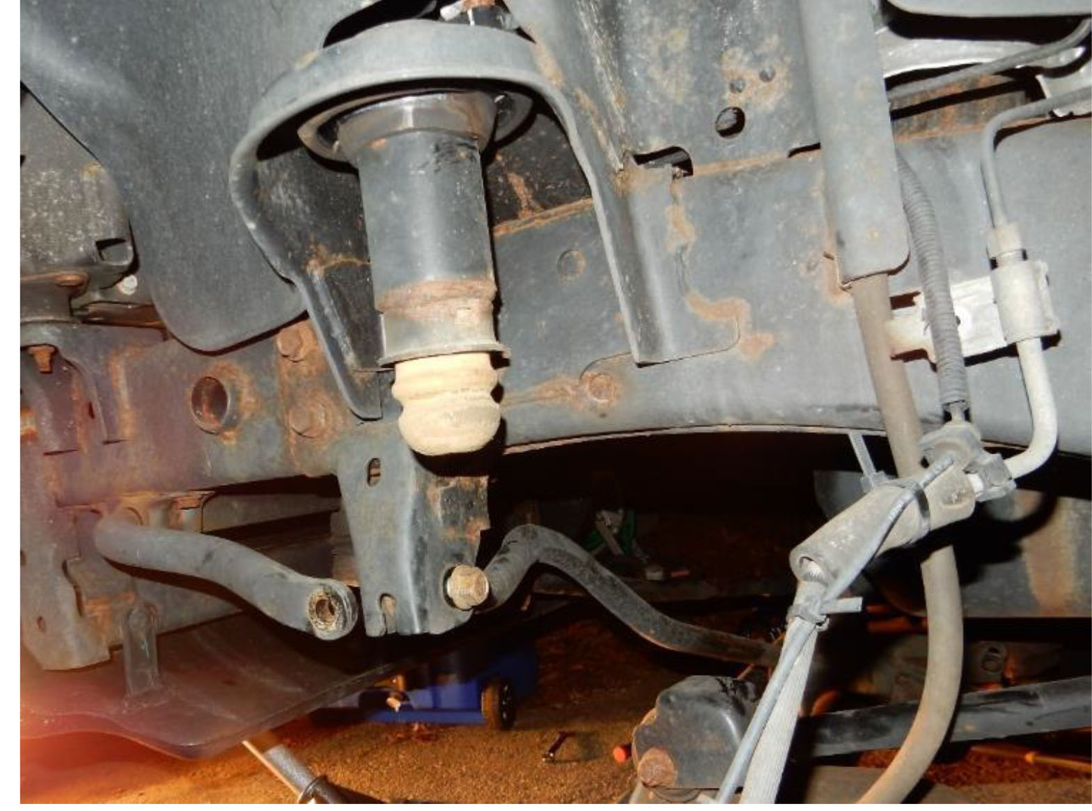
55. Install the factory bumpstop into the bumpstop extension.
Note: Use grease to lubricate the factory bumpstop prior to installing into the extension.
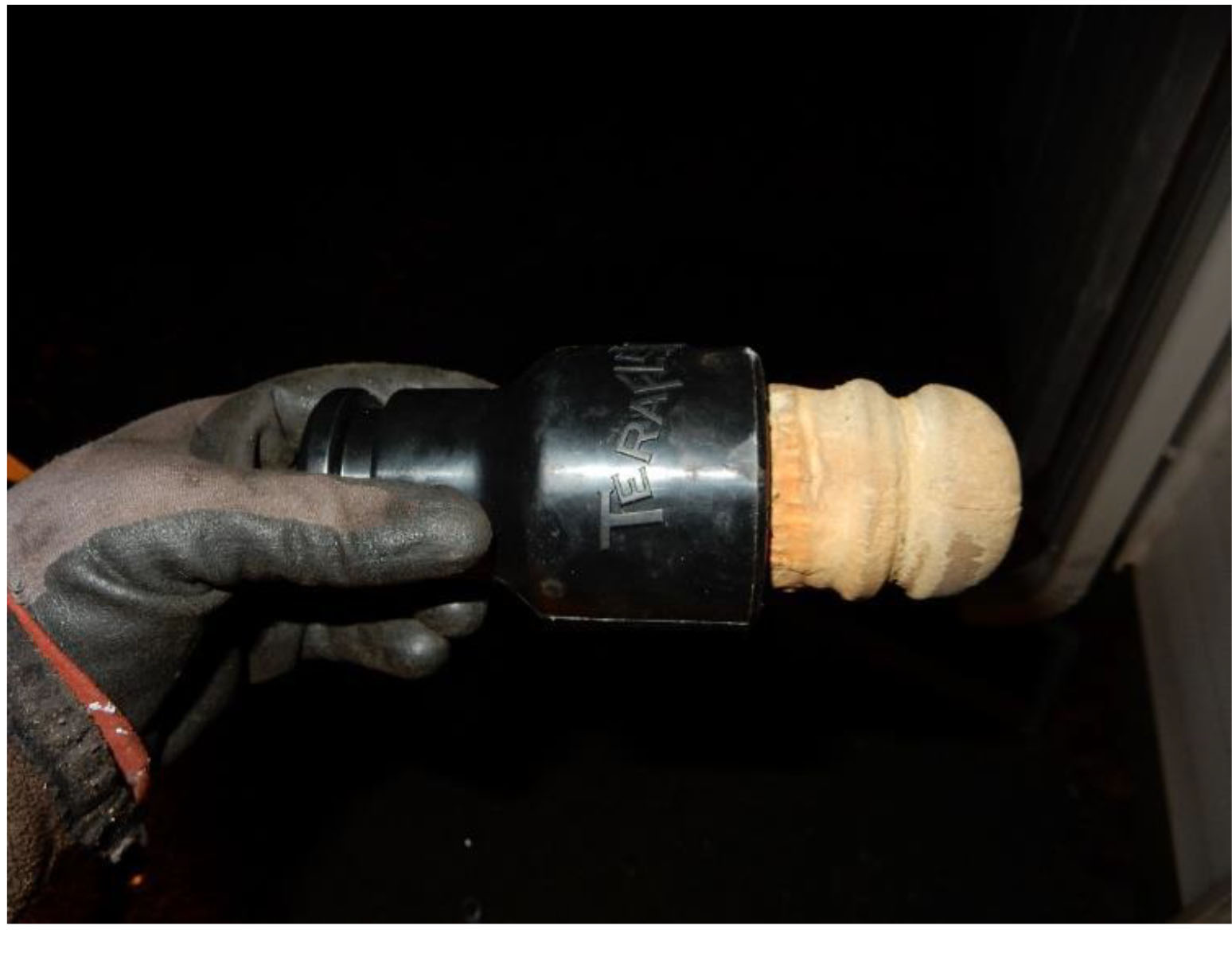
56. Install the bumpstop extension into the spring tower.
Note: Use grease to lubricate the bumpstop extension prior to installing into the extension. Note: Use the floor jack to raise the axle and press the bumpstop extension into place.
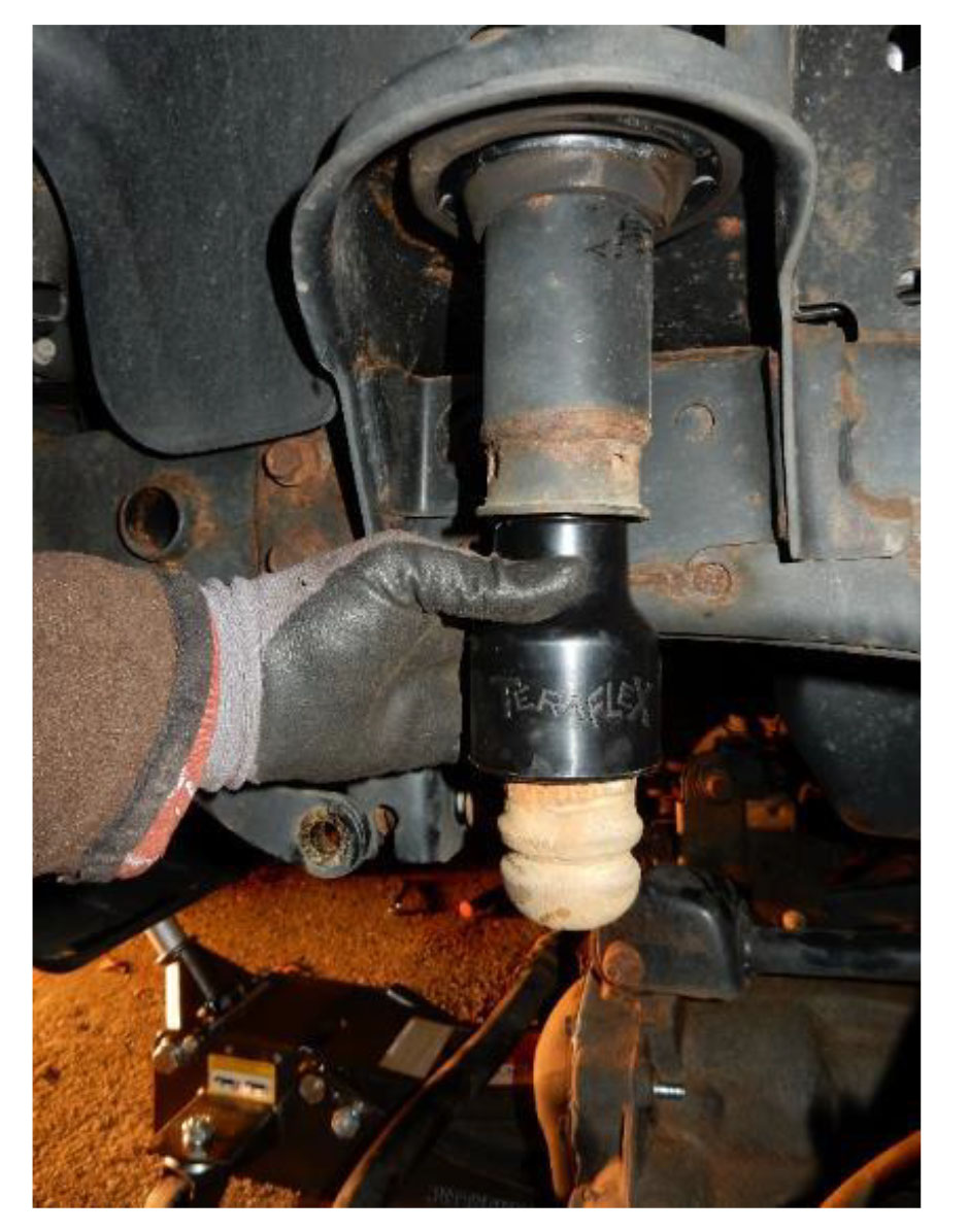
57. Install new springs into position.
Note: Install the driver side spring first, followed by the passenger side. Note: The tight wrapped coil is the located at the top of the spring.
58. Install a retaining washer and rubber bushing onto the shaft of the new shock. Position the shocks into place with the shaft installed through the shock tower. Install the remaining rubber bushing, retaining washer, and nut onto the shock shaft on the driver and passenger sides. Using a 16mm wrench, torque to 20 ft-lbs.
Note: Install the rubber bushing so the larger extrusion is to the top.
Note: The lower shock bolt can be used to hold the shock in place until the top nut can be started.
59. Using an 18mm socket and wrench, torque the lower shock bolt to 57 ft-lbs on the driver and passenger sides.
60. Position the rear sway bar link on the front sway bar on the driver and passenger sides. Using an 18mm wrench, and a 19mm wrench to keep the stud opposite the nut from spinning, install the nut in the sway bar side of the sway bar link on the driver and passenger sides. Torque to 75 ft-lbs
Note: The sway bar link installs to the outside of the sway bar.
61. Using and 18mm socket and wrench, install the axle side bolt into the sway bar and torque to 75 ft-lbs.
Note: The sway bar link installs to inside of the axle mount.
62. Reinstall tires. Using a 19mm socket reinstall lug nuts. Torque to 95-115 ft-lbs.
Note: Do not torque lug nuts until vehicle is on the ground.
63. Lower the vehicle to the ground.
Note: Remove the chock from the front tires after all bolts have been properly torqued.
64. Torque all control arm bolts to the specified settings.
65. Position the front track bar in place at the frame mount. Using a 21mm wrench and socket, reinstall the factory bolt and nut. Torque to 125 ft-lbs.
Note: Do not torque bolt until vehicle is on the ground and at ride height.
66. Position the front track bar in place at the axle mount. Using a 21mm wrench and socket, reinstall the factory bolt and nut. Torque to 125 ft-lbs.
Note: Do not torque bolt until vehicle is on the ground and at ride height.
Note: Having someone turn the steering wheel aids in the alignment of the track bar and axle mount bolt holes.
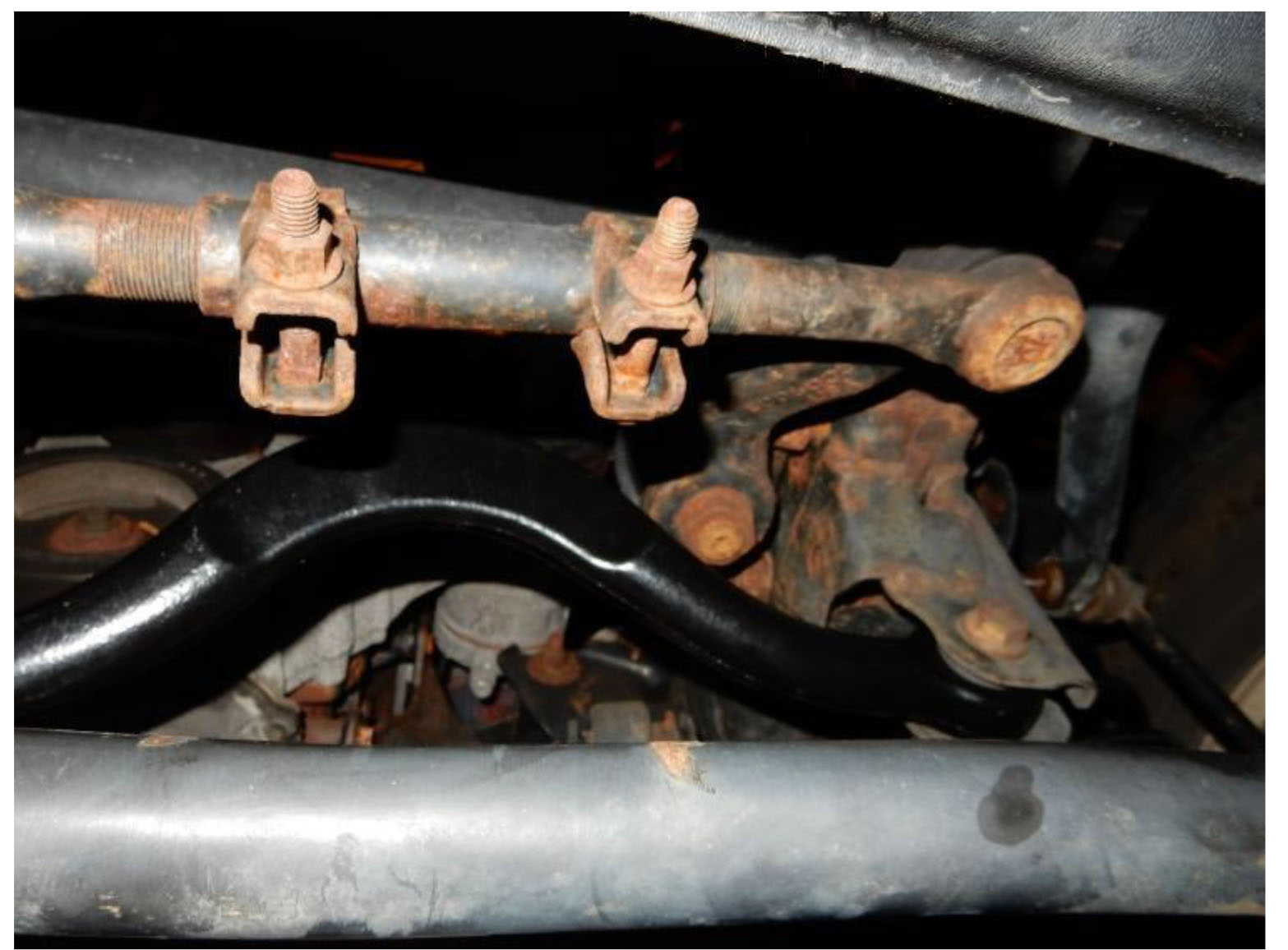
67. Mark the adjuster sleeve of the drag link to note the factory setting, to be used as a base point.
68. Using a 15mm socket, loosen the nuts on the adjuster sleeve of the drag link. Rotate the adjuster sleeve of the drag link clockwise approximately 3/4 of a turn or as needed until the steering wheel is straight.
69. Using a 15mm socket tighten the nuts on the adjuster sleeve of the drag link. Torque to 45 ft-lbs.
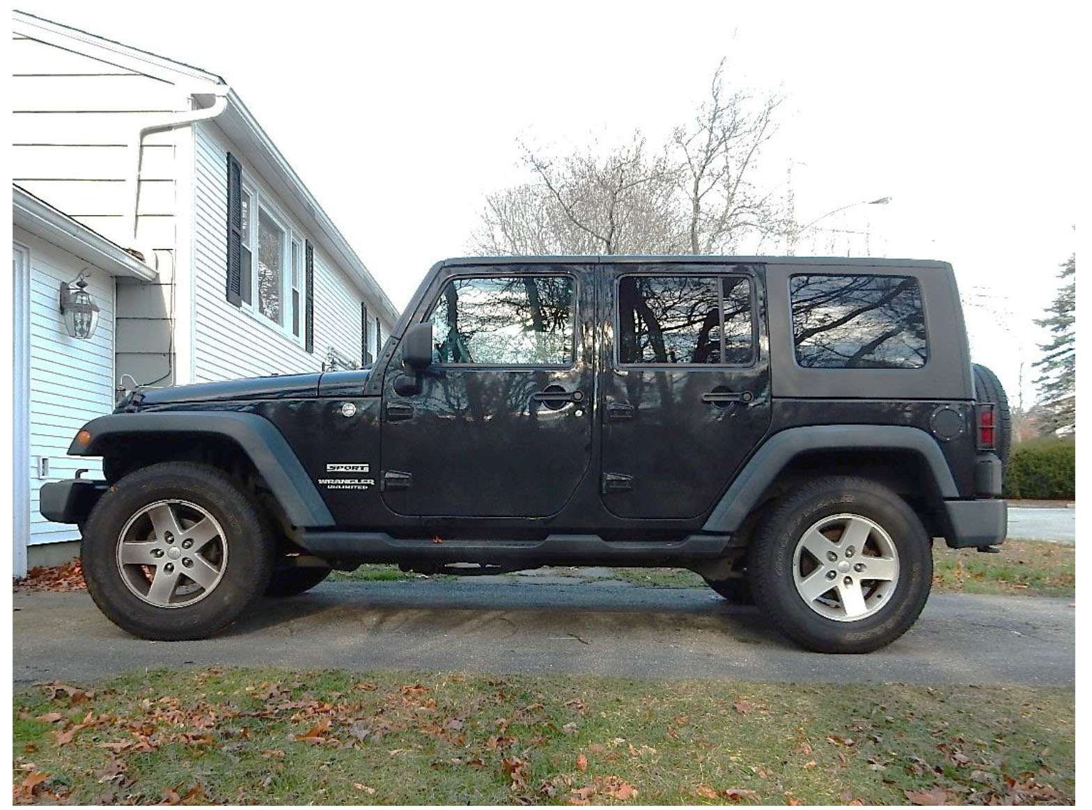
Before Install:
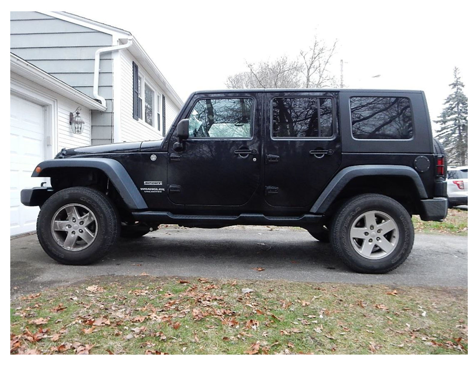
After Install:
Installation Instructions Written by ExtremeTerrain Customer Ryan Field 0/08/2016
