

How to install a Synergy Standard Transmission Skid Plate - Black Powder Coated on your Wrangler
GENERAL NOTES:
• These instructions are also available on our website; www.synergymfg.com. Check the website before you begin for any updated instructions and additional photos for your reference.
• The installation of this skid plate assembly requires drilling and tapping of threaded holes.
• You have the option to use the factory hex head bolts in the factory skid plate holes for installation of the T-Case skid plate or to drill and tap them and use the supplied flat head allen head bolts.
• You will need a 29/64 drill bit and 112-20UNF tap.
• This skid plate assembly is designed to be used as complete assembly in conjunction with the stock cross member. None of the factory skid plates will be used.
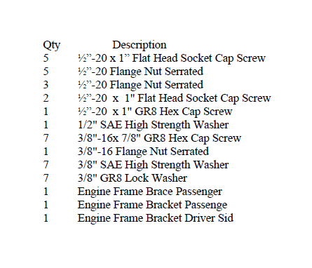
Included Components
INSTRUCTIONS:
1. Remove the skid plates, one covering the T-Case and one covering the automatic transmission if equipped.
2. Retain the bolts used for the stock skid plates. These will be used to mount the new crossmember skid plate.
3. Install the new crossmember skid plate, use 3 stock bolts removed from the
original skid plates.
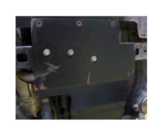
4. Tighten the 3 factory cross member mounting bolts to 35 ft-Ibs.
5. Now is a good time to drill and tap the rear hole in the frame on the driver side and the gas tank skid plate tab for installation of the transfer case skid plate. This will allow for flush mounting hard- ware to be used.
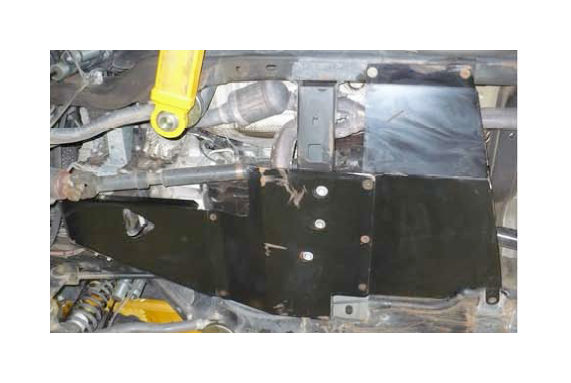
6. You can now install the rear transfer case skid plate, install the skid plate on top of the
cross- member skid plate. If you drilled and tapped the gas tank and frame hole to %-20, use the supplied flat head allen bolts, if not us the original bolts, tighten to 35 ft-Ibs.
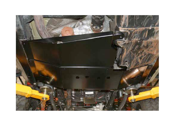
7. Install the 3 center %·20" flat head allen bolts with the flange nuts and tighten to 35 ft·lbs.
8. Loosen the driver side engine mounting bolt and tap rearward with a hammer. Slide the engine mount frame bracket under the bolt as shown. Attach the bottom of the bracket with a 3/8" bolt, washer and flange nut. Tighten the 3/8" bolt to 20 ft-lbs and then tighten the engine mount bolt to 45 ft-lbs.
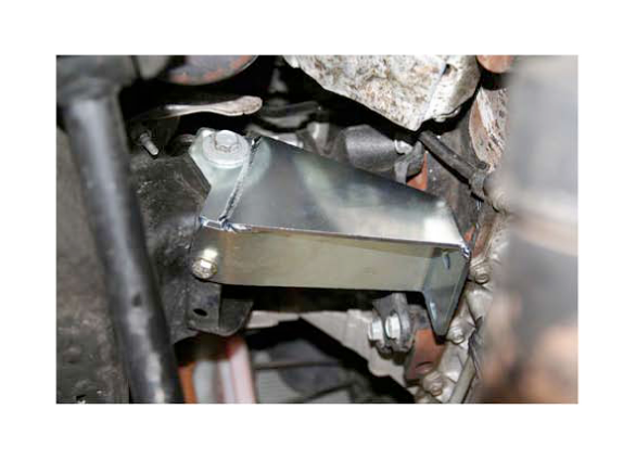
9. Install the driver side frame brace to the frame bracket; the driver side is the shorter of the two. There is no top or bottom and can be installed in either direction. Use the supplied 3/8 bolts, flat washers and lock washers. Leave these bolts loose until all the other pieces are installed.
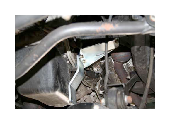
10. Install the front engine skid plate, put the rear on top of the crossmember skid plate and attach the front to the driver side frame brace. Using the W' flat head allen bolts and flange nuts, attach the rear of the engine skid to the front of the crossmember skid. Do not tighten these bolts yet; leave them loose until both of the front brackets are installed.
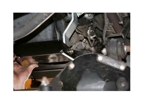
11. Install the passenger side frame brace as shown with the larger hole in the top. Use a W' bolt with a flat washer and flange nut on the top and two 3/8" bolt with a lock nut and flat washer on the bottom.
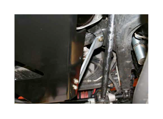
12. Adjust the side to side position of the front engine skid and tighten all the mounting bolts. Tighten the 3/8" bolts to 20 ft-Ibs and the W' bolts to 35 ft-Ibs.
Installation is Complete
