 FREE 1 to 3-Day Delivery on Orders $149+ Details

How to Install Synergy Rear Lower Control Arm Skids w/ Integrated Shock Mounts (07-18 Wrangler JK) on your Jeep Wrangler

Shop Parts in this Guide
GENERAL NOTES:
These instructions are also available on our website at www.synergymfg.com Check the website for any updated instructions and additional photos for reference.
Note: Some cutting and grinding of the factory control arm mount is required for installation.
Bracket is designed to be bolted on but can be welded on as well if desired. (NOTE: If bracket is being used as a lower coil over mount, we strongly recommend the bracket be welded on)
PARTS LIST:
2 – PPM-8078 JK Rear LCA skid / shock mount
2 – 1/2 -13 UNC bolt 2.75” long
2 – 1/2 -13 UNC stover nut
4 – 1/2” flat washers
4 – 3/8-16 UNC bolt 1” long
4 – 3/8-16 UNC stover nut
8 – 3/8” flat washers
2 – 9/16 - 12 UNC bolt 4.5” long
2 – 9/16 - 12 UNC stover nut
4 – 9/16” flat washers
INSTRUCTIONS:
1) Begin by removing the rear TB bolt and nut at the frame side (#2 in picture below). This is easiest to do with the vehicle still sitting on the ground under its own weight.
2) Jack the vehicle up allowing the rear suspension to hang free. Support the vehicle using jack stands and remove both rear tires.
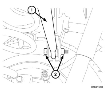
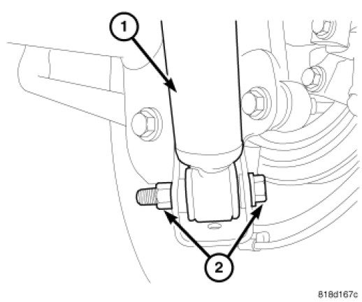
3) Remove both lower shock bolts (2)
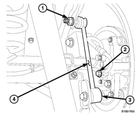
4) Remove sway bar link where it attaches to axle. (3)
5) Remove the lower control arm.
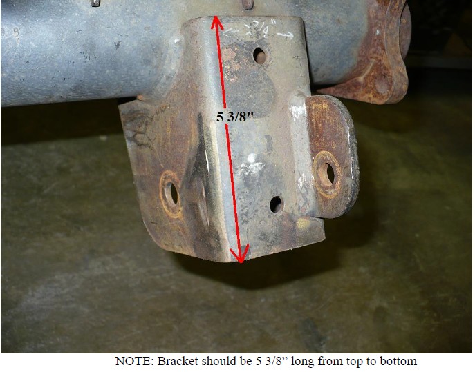
6) Next, cut off the stock lower shock mount on the control arm bracket. A 4 ½” angle grinder works great for this. Once the shock mount is off, cut 1.75” off the bottom of the control arm mount. Grind smooth all cuts. The stock control arm bracket should look like this after all cuts have been made:
7) Now fitment of the new PPM-8078 JK Rear HD lower shock mount can begin. Slide the new bracket over the stock control arm bracket. This may require gentle tapping with a rubber mallet depending on how tweaked the factory mounts are from wheeling abuse.
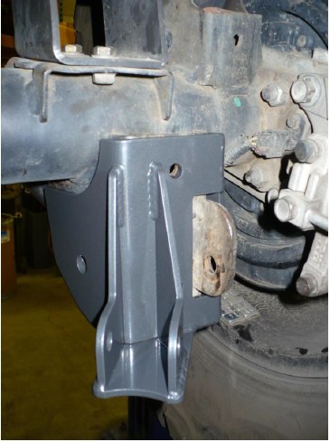
8) Align the bracket so the 4.5” long 9/16” bolt provided in the kit can be slid through. Put a washer on both ends and start the stover nut. Do not install the control arm at this time. Do not fully tighten at this time.
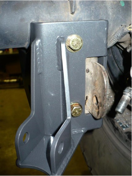
9) Start the 3/8” diameter 1” long bolts provided in the kit into the two rear holes. Put a washer under the head of the bolt and under the nut. Start the stover nut but again do not tighten at this time.
10) Tighten the 9/16” control arm bolt as to not allow the bracket to move. Then tighten the 3/8” bolts on the back side of the bracket. Torque these to 40 ft-lbs.
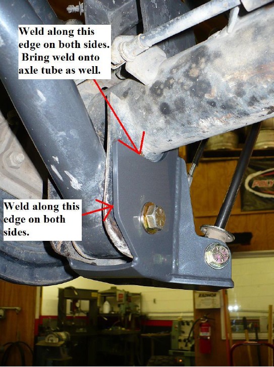
(NOTE: If bracket is welded on, now is the time to do so. Clean areas where planning to weld and weld bracket on at this time. See picture below for weld area recommendations.
11) Next, remove the 9/16” control arm bolt and reinstall lower control arm. Wait to tighten control arm bolts until vehicle is sitting on the ground under its own weight.
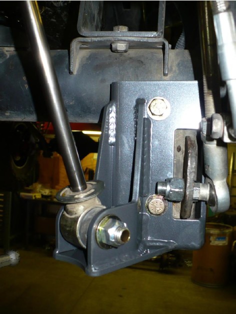
12) Reinstall shock into new lower shock mount using the 2.75” long ½-13 UNC bolts provided in the kit. Also, reconnect sway bar end link onto axle. Tighten both to 75 ft-lbs.
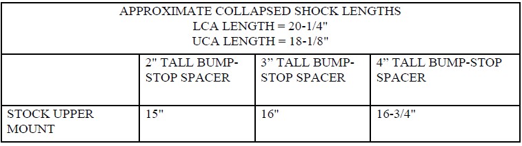
13) Note, now is a good time to cycle suspension to check for proper bump-stop spacing to ensure shock does not act as bump stop. Use the approximate collapsed shock measurements below as a reference.
14) Reinstall wheels and lower vehicle onto ground. Tighten Lower Control arm bolts to 125 ft-lbs. Reinstall Track-bar bolt and tighten to 125 ft-lbs.

