FREE 1 to 3-Day Delivery on Orders $149+ Details

How to Install Synergy Rear Control Arm Frame Brackets (07-18 Wrangler JK) on your Jeep Wrangler
Installation Time
2 hours
Tools Required
- Basic simple hand tools
- A plasma cutter or oxy-acetylene torch
- grinder with a cut off wheel or a sawzall
- Floor jack or automobile lift
- two sturdy jack stands
- Drill and 9/16” Drill Bit

Shop Parts in this Guide
General Notes:
These instructions are also available on our website; www.synergymfg.com. Check the website before you begin for any updated instructions and additional photos for your reference.
Removal of the fuel tank is required for removal of the passenger rear lower control arm bracket and to access the rear control arm bracket nut tab.
The installation of these control arm brackets requires major cutting and grinding. Most of the factory control arm mounts on the frame will need to be cut off and ground smooth.
Removal of fuel tank is required for passenger rear lower control arm bracket.
PARTS LIST:
8030 – JK Rear Long Arm Frame Brackets
(1) 8030-01-L Rear Long Arm Frame Side Bracket, Left Side
(1) 8030-01-R Rear Long Arm Frame Side Bracket, Right Side
(1) 803002-L Long Inside Frame Rail Nut Tab, Left Side
(1) 803002-R Long Inside Frame Rail Nut Tab, Right Side
(2) 803003 Short Inside Frame Rail Nut Tab
(2) 803004 Bottom Frame Rail Nut Tab
(8) 1/2”-13 UNC x 1.5” long hex head bolt
(8) 1/2” GR8 flat washer
(4) 9/16”-12 UNC x 4” long hex head bolt
(4) 9/16”-12 UNC stover lock nut
(8) 9/16” GR8 flat washer
(2) 1/2”-13 UNC x 1.25” long flat head socket cap screw
INSTALLATION:
REMOVAL OF STOCK REAR CONTROL ARM BRACKETS
1) Remove the stock upper and lower control arms.
2) Remove the fuel tank. You must remove the fuel tank to remove the passenger rear lower control arm bracket and to access the inner wall of the frame to install one of the nut tabs. Refer to the factory service manual for the exact procedure.
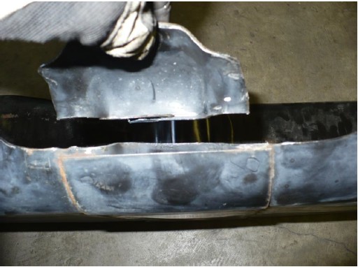
3) Using a cut-off wheel, cut the sides of the lower control arm bracket as shown below. Cut just below the welds on the frame. Be careful to not cut through the frame. Cut the weld on the front of the control arm bracket on the bottom of the frame.
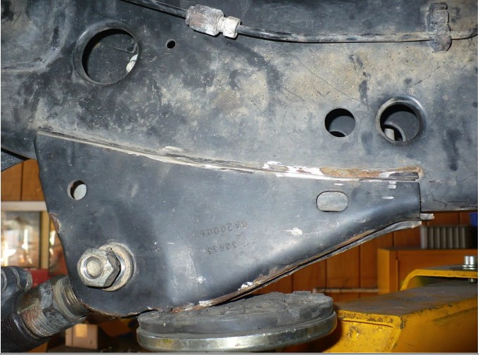
4) Cut off the upper control arm bracket as shown below
5) Trim the bottom of the rear body mount. Leave about 1 1/8” from the top surface of the body mount to cut edge.
6) Grind the welds and smooth where you removed the control arm brackets and body mount. The side and bottom where the new control arm bracket is located needs to be smooth, the inside of the frame and the upper control arm bracket do not need to be completely cleaned off.
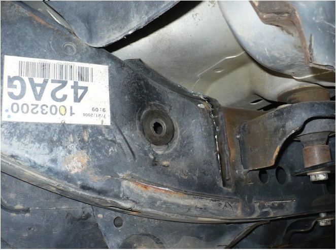
7) Remove the threaded insert for the gas tank bracket just in front of the lower control arm bracket. Strike the head of the bolt upward with a large hammer to break the threaded insert loose from the frame. Remove the threaded insert and bolt.
8) Cut off the mounting tab on the gas tank skid that is located just in front of the lower control arm bracket.
INSTALLATION OF REAR CONTROL ARM BRACKETS
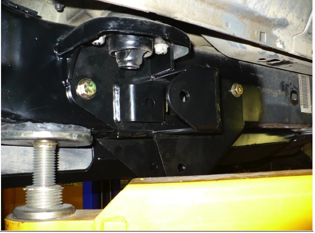
9) Remove the two body mount nuts and the large center body mount bolt. Position the new control arm bracket over the body mount studs. Reinstall the nuts onto the body mount studs and tighten.
10) Using the control arm bracket as a guide, mark and drill the frame for the control arm bracket mounting bolts. Use at least a 9/16” drill bit.
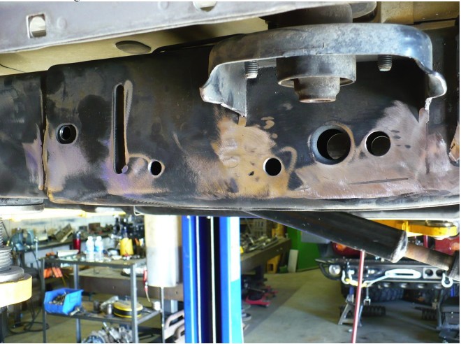
11) Cut a rectangular hole in the frame on the driver side, similar to the hole on the passenger, you can use the control arm bracket as a guide. A round hole cut with a hole saw will also work, this is just for access to the front nut tab and to install the lower nut tab.
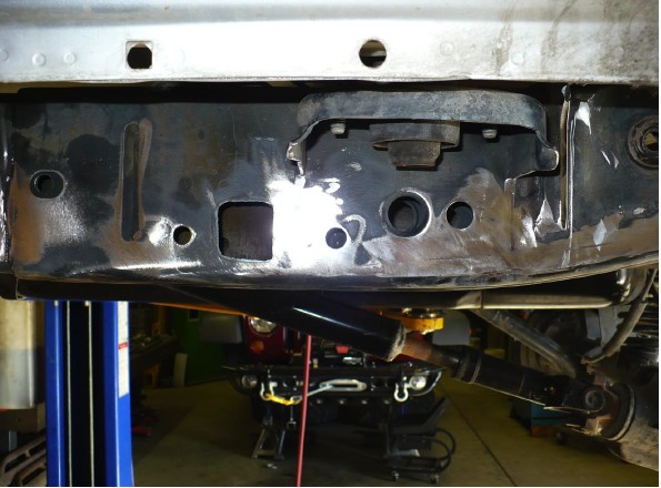
12) Clean, deburr and paint the frame where the stock brackets were removed.
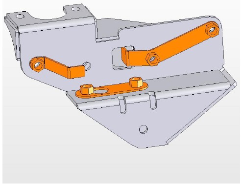
13) Insert the front and lower nut tabs through the rectangular hole in the frame. Refer the picture below for the nut tab orientation. The rear nut tab must be accessed through an existing hole on the inside of the frame.
14) Reinstall the control arm bracket to the body mount studs and tighten the body mount nuts to 40 ft-lbs.
15) Install the 1/2” bolts with washers in the control arm bracket into the nut tabs. Tighten the control arm bracket bolts to 90 ft-lbs.
16) Trim the large washer under the body mount bolt to clear the upper control arm joint. Install the large body mount bolt and torque to 80 ft-lbs.