 FREE 1 to 3-Day Delivery on Orders $149+ Details

How to Install Synergy Heavy Duty Rear Lower Control Arm Frame Brackets (07-18 Wrangler JK) on your Jeep Wrangler
Installation Time
2 hours
Tools Required
- Quality jack & jackstands
- Basic simple hand tools
- Metal cutting tools
- Angle grinder / cutting torch / sawzall / plasma cutter
- Grinding / sanding attachments
- Welding machine

Shop Parts in this Guide
GENERAL NOTES:
These instructions are also available on our website; www.synergymfg.com. Check the website before you begin for any updated instructions and additional photos for your reference.
This is a weld on part and should be installed by an experienced welder.
This part requires significant cutting & grinding of the factory control arm brackets.
Be sure to disconnect the ground cable from the battery prior to welding as to prevent electrical damage to the vehicle.
**Note** Gas tank removal will be required for installation of the passenger side frame bracket. Steps 2- 16 will cover gas tank removal.
PARTS LIST:
5020-01 JK, 07-PRESENT, REAR, HEAVY DUTY LOWER CONTROL ARM FRAME BRACKET
(2) 5020-01 JK Rear Lower Control Arm Frame Brackets (1L & 1R)
INSTALLATION:
1) Install one side at a time so that one side can be used as a reference to measure against.
2) Begin by removing gas tank as it is necessary for passenger side bracket installation.
3) Drain the gas from the tank if it’s not close to empty. You can do this by removing the filler hose from the fuel tank and inserting a drain hose, it needs to be a small hose because there is a flapper valve installed into the opening.
4) Remove the stock T-case skid plate or any aftermarket T-case skid plate
5) Loosen and remove the passenger side rear lower control arm bolt, pull the bolt out so it is flush with the inside of the lower control arm bracket
6) It is very helpful to remove and install the tank if you remove the right rear coil spring and disconnect the drive shaft at the pinion.
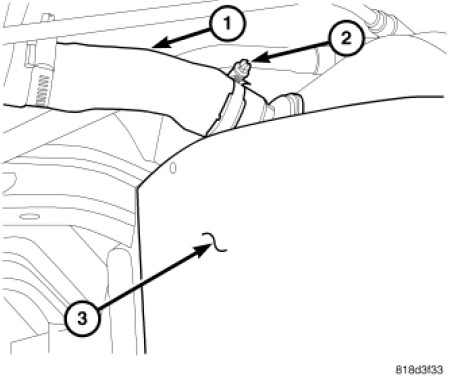
7) Remove fuel fill hose clamp (2) at rear of tank (3).
8) Remove fuel fill hose (1) from fuel tank.
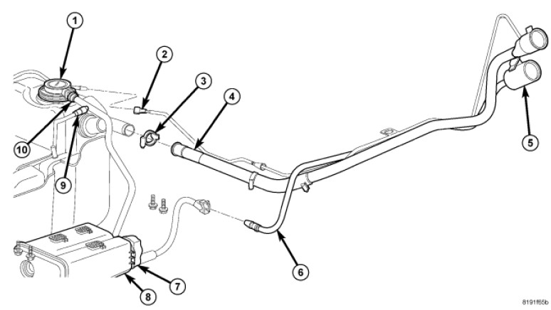
9) Disconnect quick-connect fitting (2), (9) and (10)
10) Support tank with a hydraulic jack.
11) The fuel tank skid plate and the fuel tank assembly are removed at the same time. They share common fasteners.
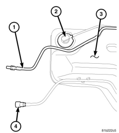
12) Disconnect quick-connect fittings at front of tank (1) and (4)
13) Remove all of the tank mounting bolts.
14) Partially lower tank to gain access to pump module electrical connector.
15) Disconnect electrical connector at fuel pump module.
16) Continue lowering tank for removal.
17) After tank is removed. Remove one rear lower control arm. You can start on either side of the vehicle. Once the arm is removed, safely raise the vehicle to a height that can easily be worked under. Allow the rear suspension to hang free and safely support the vehicle with a quality jack and jack-stands.
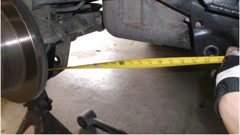
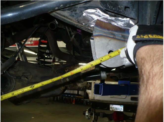
18) Next, take some reference measurements. For example:
Rear lower control arm mount at axle to rear lower control arm mount on frame. Center of holes to center of holes. This measurement will vary depending on what lower control arms are installed in vehicle.
19) With measurements in hand, begin cutting rear lower control arm mount off the vehicle.
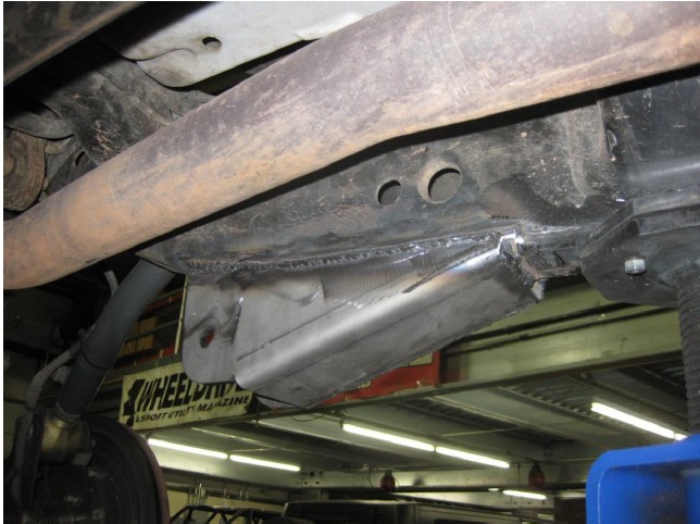
20) Begin by cutting the outer half of the bracket off, as shown below. This may take multiple cuts to complete.
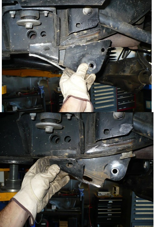
21) Next, carefully cut the inner part of the lower control arm bracket as shown below. Be careful not to cut through the frame.


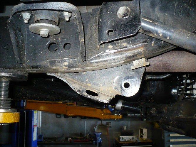
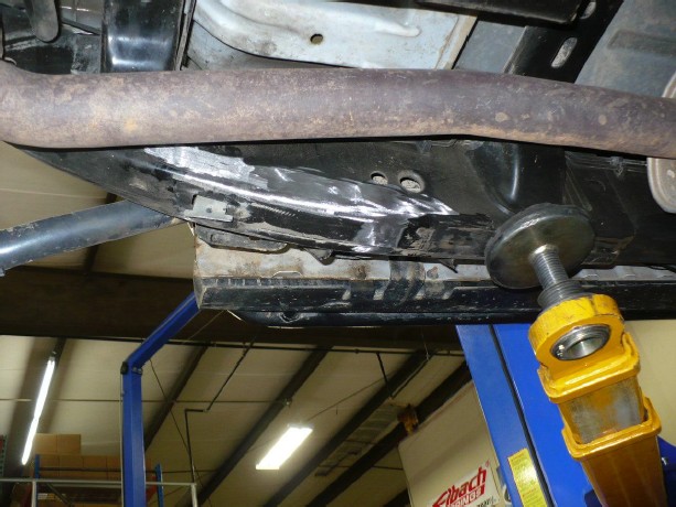
22) With bracket fully removed as shown above, grind smooth the frame.
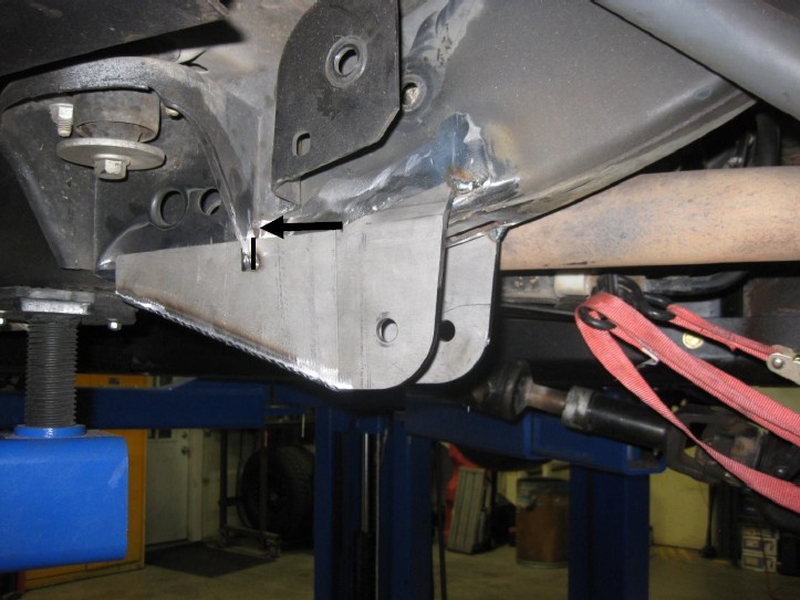
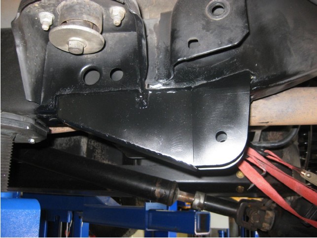
23) Test fit the bracket. The keyway on the bracket was intended to self-locate the bracket off the body mount as shown below. The rear side of the keyway should meet with the rear side of the body mount.
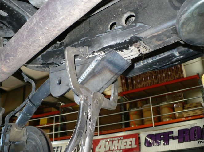
24) Use a clamp to hold the bracket into position and match the measurements taken in step 18.
25) Once satisfied with fitment, tack weld into position. Tack securely in several places.

26) After tack welding to satisfaction, reinstall control arm and take some reference measurements to ensure accurate placement.
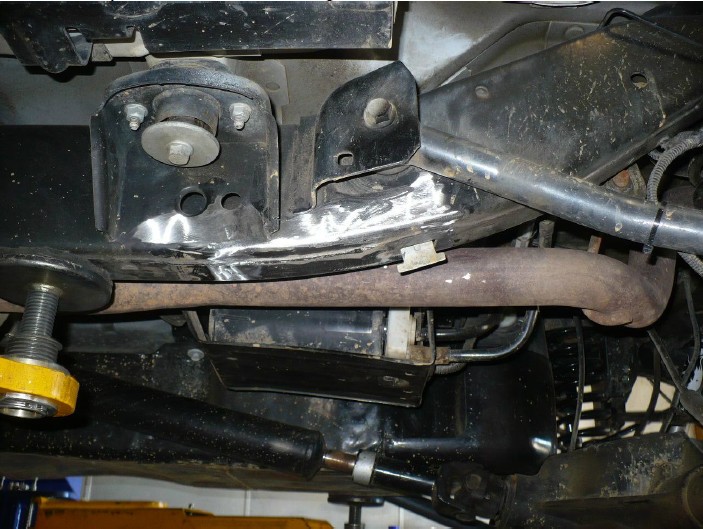
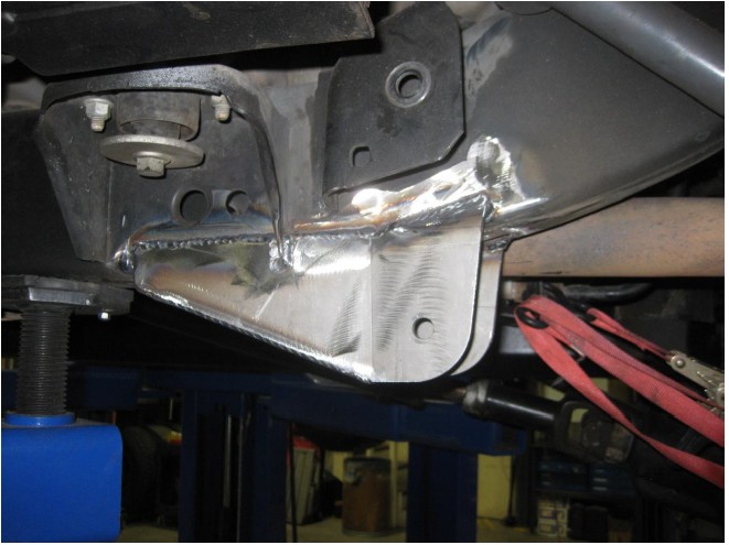
27) Remove control arm and fully weld in position. Weld as much as desired, we recommend welding as shown below.
28) Allow welds to cool. Deburr welds and paint to prevent corrosion.
29) Installation on one side is complete.
30) Follow the same procedure on the opposite side. Reinstall gas tank in the reverse order of removal (steps 2-15) Tighten the factory gas tank frame bolts to 30 ft-lbs.
31) Reinstall any control arms removed for installation of gusset kit and torque to mfg specifications. (125 ft-lbs for OEM, or 9/16” Gr8 hardware.)
Installation is Complete

