 FREE 1 to 3-Day Delivery on Orders $149+ Details

How to Install SuperLift 4 in. Suspension Lift Kit w/ Shocks (12-17 Wrangler JK 2 Door) on your Jeep Wrangler
Shop Parts in this Guide
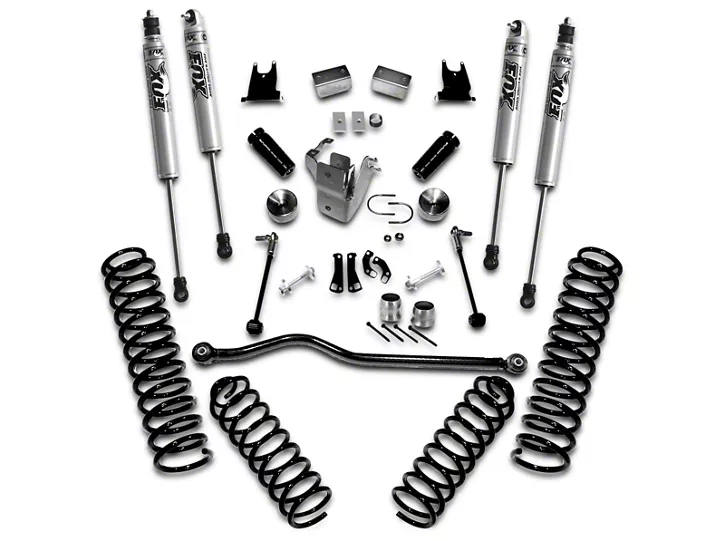
- SuperLift 4-Inch Suspension Lift Kit with Shocks (12-18 Jeep Wrangler JK 2-Door)
- SuperLift 4-Inch Suspension Lift Kit with Shocks (07-18 Jeep Wrangler JK 4-Door)
- SuperLift 4-Inch Suspension Lift Kit with Reflex Control Arms and Shocks (07-18 Jeep Wrangler JK 2-Door)
- SuperLift 4-Inch Suspension Lift Kit with Reflex Control Arms and Shocks (07-18 Jeep Wrangler JK 4-Door)
INTRODUCTION
Installation requires a professional mechanic. The overall vehicle must be in excellent working condition; repair or replace all worn parts.
Read instructions several times before starting. Be sure you have all needed parts and know where they install. Read each step completely as you go.
NOTES:
• Prior to beginning the installation, check all parts and hardware in the box with the parts list below. If you find a packaging error, contact Superlift® directly. Do not contact the dealer where the system was originally purchased. You will need the control number from each box when calling; this number is located at the bottom of the part number label and to the right of the bar code.
• A precision steering alignment, including the centering of the steering wheel, is required in order for the vehicle’s Electronic Stability Program to function properly. Using “all laser” alignment equipment is recommended.
• 33” - 35” tires can be used without fender trimming, however the use of a 37” tire will require fender trimming.
• Maximum tire width = 12.5”; Minimum tire diameter = 17”; Wheel width 8-9”; Minimum backspacing = 4.5”; Maximum backspacing = 4.75”
• Stock wheels can be used with 33” tires. If 35” or 37” tires are used with stock wheels, 1.5” wheel spacers are required for tires to clear frame rails and allow full turning radius.
• 2 Door Wranglers - Due to increased driveshaft operating angles and short shaft length, factory rear driveshaft life will be reduced. When replaced, Superlift suggests converting to a dual cardan style shaft. These shafts can be purchased at many driveshaft shops.
• An arrow on diagrams indicates which direction is toward the front of the vehicle.
• A foot-pound torque reading is given in parenthesis ( ) after each appropriate fastener.
• Do not fabricate any components to gain additional suspension height.
• Prior to drilling or cutting, check behind the surface being worked on for any wires, lines, or hoses that could be damaged. After drilling, file smooth any burrs and sharp edges.
• Paint or undercoat all exposed metal surfaces.
• Prior to attaching components, be sure all mating surfaces are free of grit, grease, excessive undercoating, etc.
• A factory service manual should be on hand for reference.
• Use the check-off box “” found at each step to help you keep your place. Two “” denotes that one check-off box is for the driver side and one is for the passenger side. Unless otherwise noted, always start with the driver side.
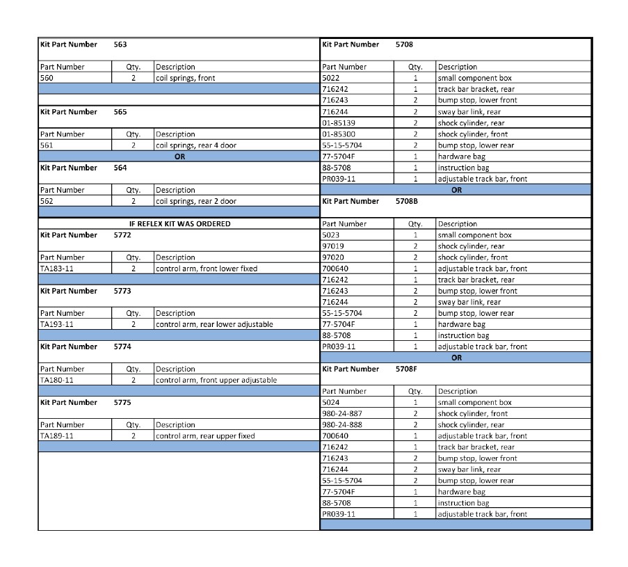
THESE ARE THE KIT BOXES YOU SHOULD HAVE RECEIVED AND THEIR CONTENTS.
FRONT DISASSEMBLY
NOTE: Save all factory components and hardware for reuse, unless noted.
1) PREPARE VEHICLE...
Place vehicle in neutral. Raise front of vehicle with a jack and secure a jack stand beneath each frame rail, behind the front / lower control arms. Ease the frame down onto the stands, place transmission in low gear or “park”, and chock rear tires. Remove front tires.
Position a jack so that it supports, but does not raise, the front axle.
2) TRACK BAR AND CONTROL ARMS…
Remove the bolts securing the front track bar-to-axle and frame.
Loosen but do not remove the upper and lower control arm bolts at the frame and axle.
3) SWAY BAR LINKS AND SHOCK ABSORBERS…
Remove and discard the front sway bar links.
Remove and discard the shock absorbers.
4) BRAKE HOSES, WIRING, AXLE VENT HOSE…
If optional extended length Bulletproof brake hoses are being used, these relocation brackets are not required. Install Bulletproof hoses now per separate instructions.
If Bulletproof hoses are not being used, detach the factory brake hose bracket (one per side) at the frame. This bracket holds the connection between the rubber brake hose and the metal brake line.
On each side, a clip attaches the ABS wire loom to the top / inboard side of the shock tower. Remove and discard the clip.
The upper end of the axle vent hose is clamped to the driver side frame rail. Leave the hose attached to frame; simply pull down approximately 3” of hose.
On Rubicon models, the wiring loom for the locking differential is attached to the axle-to-frame upper link. Remove and discard the clip.
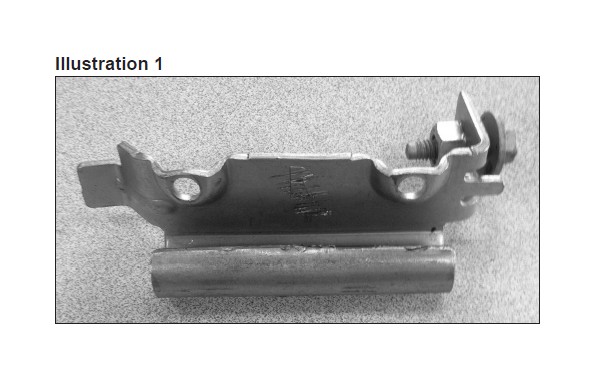
[Illustration 1] Carefully pry the factory brake line bracket from the rubber hose. DO NOT DAMAGE THE HOSE IN THE PROCESS. If the hose is damaged it MUST be replaced.
5) DRIVESHAFT…
Unbolt the front driveshaft at the front axle then tie it up and out of the way. Do not let the shaft “hang”; this risks pinching / damaging the grease boot at the transfer case end.
6) COIL SPRINGS AND BUMP STOPS…
Loosen, but do not remove, the upper and lower control arm bolts at the axle and frame.
Lower the axle enough to facilitate removing the front coil springs.
FRONT ASSEMBLY
NOTE: If installing Superlift Reflex control arms continue with steps below, if retaining the factory control arms proceed to step 10.
7) REFLEX UPPER CONTROL ARM PREPARATION…
Reflex control arm length, measured from center of eye-to-center of eye, must measure 18-1/2”; verify that both control arms are set to this length. If adjustment is necessary, rotate the threaded end accordingly.
8) REFLEX UPPER CONTROL ARM INSTALLATION…
NOTE: Perform the steps in step 8 one side at a time, starting on the passenger side. Not all steps are required on driver side.
Loosen, but do not remove, the single bolt that connects the passenger side motor mount to-frame.
Remove the three nuts that secure the transmission isolator-to-transmission crossmember.
Position a jack with a block of wood under the oil pan. Raise the jack so that the engine will tilt / rotate towards the driver side of vehicle. This will allow clearance needed to remove the control arm bolt at the frame on the passenger side without removing the exhaust.
Remove the bolt from the factory control arm’s axle and frame ends then remove control arm.
Attach the bushing end of the Reflex control arm-to-frame using the factory bolt and tab nut. Do not tighten yet.
Attach the bracket end of the Reflex control arm-to-axle using the factory hardware. Do not tighten yet.
Lower the jack supporting the oil pan.
Tighten the motor mount hardware on the passenger side (80).
Reinstall the three nuts that secure the transmission isolator-to-transmission crossmember (40).
Repeat appropriate steps for driver side control arm installation. On this side it is not necessary to loosen motor and transmission mounts, nor elevate the engine; simply remove the factory control arm then install the Reflex unit. Again, do not tighten any hardware at this time.
9) REFLEX LOWER CONTROL ARM INSTALLATION…
NOTE: Perform the steps in step 9 one side at a time
Remove the factory front lower control arm.
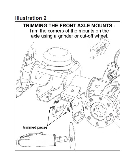
[Illustration 2] Using a grinder, clearance the lower control arm mounts at the axle, as shown. Not much clearancing is required; simply remove the mount’s top radius.
When installing the Reflex control arms they do need to be orientated correctly. The bend in the arm should point up when installed. Attach the Reflex control arm-to-frame using the factory hardware; install the bolt from the outside. Do not tighten the control arm bolt yet.
One side at a time, remove the rear knock-outs that change the opening from a square hole to a slotted hole. A special tool is available for this, or use a die grinder with a small cutting wheel.
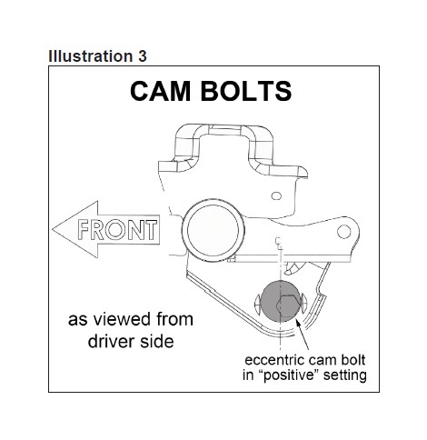
[Illustration 3] Reconnect lower control arms to the axle using the supplied cam bolts (#77-5704A), installed from the outside. Rotate the cams to their “most positive” setting, so that the front axle is shifted as far forward as possible (the bolt head will be in its most rearward position). Snug-up the bolts; do not fully tighten at this time.
10) CAM BOLTS…
One side at a time, remove the bolt securing the lower control arm to the axle then remove the rear knock-outs that change the opening from a square hole to a slotted hole. A special tool is available for this, or use a die grinder with a small cutting wheel.
[Illustration 3] Reconnect lower control arms to the axle using the supplied cam bolts (#77-5704A), installed from the outside. Rotate the cams to their “most positive” setting, so that the front axle is shifted as far forward as possible (the bolt head will be in its most rearward position). Snug-up the bolts; do not fully tighten at this time.
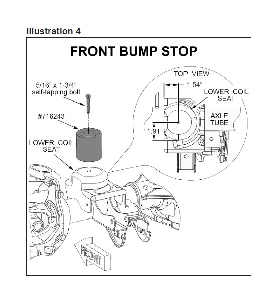
11) BUMP STOP SPACERS… [Illustration 4]
One bump stop spacer (#716243) installs on top of each coil spring’s lower seat. The other wise round seat has a flat edge that faces outboard. Locate center for the hole to be drilled by using the dimensions in illustration 3; note that the bump stop spacer is installed slightly outboard of seat center. Drill at the marked location using a 17/64” bit.
Thread the just-drilled hole using the supplied 5/16” x 1-3/4” self-tapping bolt then remove the bolt.
NOTE: The bump stop spacer must first be inserted into the coil spring before it is bolted to the coil seat; see next step.
Perform step below one side at a time.
12) COIL SPRINGS AND SHOCK ABSORBERS…
Be sure the factory rubber isolators are still in place inside the coil spring tower.
Insert the bump stop spacer (#716243) into the bottom of the coil spring and hold it in place. Insert the upper end of the coil spring into the tower first, followed by the lower seat. Be sure that the coils are indexed so they seat properly then raise the axle enough to hold the coil springs in place.
Position the bump stop spacer onto the lower spring seat then secure it using the supplied 5/16” x 1-3/4” self-tapping bolt and tighten (200 in-lb).
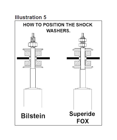
[Illustration 5] Install shock absorbers. If using Superide shocks the shock body should be bolted to the axle with the shaft mounted to the frame. The Fox shocks come with the hardware installed so the body mounts to the frame and the shaft to the axle. Tighten the upper hardware until bushings swell slightly. Install the factory lower shock bolts and nut. Do not tighten at this time. Apply shock decals. After the shock absorber installation is complete, the jack can be lowered and relocated to allow installation on the opposite side.
13) TRACK BAR…
Set the overall length of the bar to 32-7/8” measured between eye centers. This will serve as a baseline prior to final adjustment. Do not tighten the jam nut at this time.
Position the adjustable end of the track bar in the mount on the axle. Insert the stock bolt to temporarily hold the track bar in place. This end of the track bar must be detached from the axle again in a later step so do not install its nut at this time.
Connect upper end of bar-to-frame using the stock bolt and nut. Do not tighten at this time.
NOTE: Final track bar adjustment and tightening are performed in later steps.
14) BRAKE HOSES…
NOTE: If optional Bulletproof brake hoses are being used, these brackets are not required.
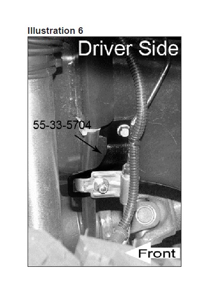
[Illustration 6] Attach the appropriate brake hose upper bracket (#55-33-5704 driver side; #55-34-5704 passenger side) to the factory brake hose. Use the supplied 1/4” x 3/4” bolt, facing outward. The washer is used on the bolt head side. Install the supplied Nyloc nut and tighten (76 in-lb).
Carefully re-form the metal brake line (do not kink the line) then attach the Superlift bracket to the factory location. (76 in-lb).
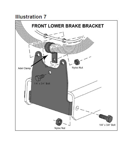
[Illustration 7] Place the new lower brake hose bracket (#55-39-5704 driver side; #55-40-5704 passenger side) on the axle using the supplied 1/4” x 3/4” bolt, washer, and Nyloc nut. (76 in-lbs)
Position the adel clamp on the brake hose, then fasten the clamp to the new Superlift bracket using the supplied 1/4” x 3/4” bolt, washer, and Nyloc nut. The steering must be cycled at this point to make sure that there is enough slack in the brake hose when the steering wheel is at full lock. If there is not adequate hose at a full lock turn, loosen the adel clamp bolt and adjust the hose as needed.
Attach the ABS line to the new Superlift bracket using the factory clips.
15) SWAY BAR LINKS…
Remove the factory rear sway bar links and install them on the front of the vehicle. (NOTE: Rubicon models must install Kit Box # 5712 per separate instructions.) Attach the swivel (upper) end of the sway bar link to the sway bar body (the stud faces inboard) then secure using factory hardware (66).
Attach the lower (eye ring) end of sway bar link to the axle. The eye ring seats against the inboard side of the mounting tab. The factory mounting bolt installs from the outboard side through the mounting tab then through the eye ring. Position one supplied .5” ID x 1.6” OD x .1875” thick washer onto the factory mounting bolt, install factory nut then tighten (75).
MODELS WITH THE CROSSMEMBER PICTURED IN ILLUSTRATION 9 MOVE TO STEP 17.
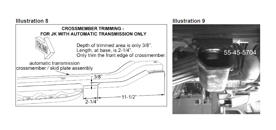
16) FRONT CROSSMEMBER, AUTOMATIC TRANSMISSION MODEL ONLY.. [Illustration 8]
Most models with automatic transmissions are equipped with a transmission pan skid plate / crossmember assembly. The forward lip of the crossmember must be trimmed to create adequate clearance between it and the driveshaft during full extension travel. The trimming process can be accomplished without removing the crossmember. Check for adequate clearance with suspension a full extension (with the front axle “hanging”). Excessive trimming weakens the crossmember.
17) [Illustration 9] Remove the three factory bolts that hold the front transmission crossmember. Install the two front spacers (#55-45-5704) and one rear spacer (#55-46-5704) between the frame and the crossmember reusing the factory hardware
18) FRONT DRIVESHAFT…
Connect the front driveshaft-to-axle using the factory hardware (81).
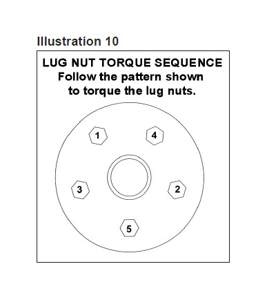
19) TIRES / WHEELS... [Illustration 10]
Tighten the lug nuts (115) in the sequence shown.
WARNING: When the tires / wheels are installed, always check for and remove any corrosion, dirt, or foreign material on the wheel mounting surface, or anything that contacts the wheel mounting surface (hub, rotor, etc.). Installing wheels without the proper metal-to-metal contact at the wheel mounting surfaces can cause the lug nuts to loosen and the wheel to come off while the vehicle is in motion.
WARNING: Retighten lug nuts at 500 miles after any wheel change, or anytime the lug nuts are loosened. Failure to do so could cause wheels to come off while vehicle is in motion.
20) INITIAL CLEARANCE CHECK, FRONT...
With the vehicle still on jack stands, and the suspension “hanging” at full extension travel, cycle steering lock-to-lock and check all components for proper operation and clearances. Pay special attention to the clearance between the tires / wheels and brake hoses, wiring, driveshaft-to-crossmember, etc.
Lower vehicle to the floor. Final tightening and adjustments to the front suspension will take place once rear lift is completed.
Install the exhaust spacer (#17606.76) at this time per separate instructions.
REAR DISASSEMBLY
21) PREPARE VEHICLE...
Place vehicle in neutral. Raise rear of vehicle with a jack and secure a jack stand beneath each frame rail, just ahead of the rear / lower control arms. Ease the frame down onto the stands, place transmission in low gear or “park”, and chock front tires. Remove rear tires.
Position a jack so that it supports, but does not raise, the rear axle.
22) TRACK BAR AND LINK ARMS…
Disconnect the factory track bar from the axle and loosen the frame attachment point.
Loosen, do not remove, the bolts securing both lower control arms to the axle and frame.
Loosen, do not remove, the bolts securing both upper control arms to the axle and frame.
23) BRAKE HOSES…
If optional extended length Bulletproof brake hoses are being used, The supplied relocation brackets are not required. Install Bulletproof hoses now per separate instructions.
If Bulletproof hoses are not used, detach the factory brake hose bracket at the frame. This bracket holds the connection between the rubber brake hose and the metal brake line.
24) WHEEL SPEED SENSOR WIRES…
On each side, at the driver side upper control arm frame mount, two clips retain the wheel speed sensor wires. Disconnect the forward-most clip from the frame mount.
25) SHOCK ABSORBERS AND BUMP STOPS…
Remove and discard the factory rear shock absorbers.
Pry the factory bump stops from their mounting cups and discard.
26) PARKING BRAKE CABLE BRACKETS, DIFFERENTIAL WIRING…
Locate the wire bracket securing the parking brake cables to the bottom of the rear floorboard, above and slightly in front of the rear axle. Unbolt the wire bracket.
On Rubicon models, a wiring loom for the locking differential clips to a bracket bolted to the top of the differential cover. Un-clip the wiring loom then either remove the bracket, or use a mallet to flatten-out the clip side of the bracket. Failure to do so will cause the wiring loom to snag on the bracket during suspension articulation.
27) COIL SPRINGS…
Lower the axle just enough to facilitate removing the coil springs. CAUTION: The driveshaft has a rubber boot on the transfer case end. If the axle is lowered too much, boot bind / damage may occur.
REAR ASSEMBLY
NOTE: If installing Superlift Reflex control arms continue with steps below, if retaining the factory control arms proceed to step 31.
28) REFLEX UPPER CONTROL ARM INSTALLATION…
NOTE: Perform the steps in step 28 one side at a time.
Remove the bolt from the factory control arm’s axle and frame ends then remove control arm.
Install the Reflex arm with the bend pointing up and the short end of the arm to the frame; secure using the factory hardware. Do not tighten at this time.
29) REFLEX LOWER CONTROL ARM PREPARATION…
Reflex control arm length, measured from center of eye-to-center of eye, must measure 19-3/4”; verify that both control arms are set to this length. If adjustment is necessary, rotate the threaded end accordingly.
30) REFLEX LOWER CONTROL ARM INSTALLATION…
NOTE: Perform the steps in step 30 one side at a time.
Remove the bolt from the factory control arm’s axle and frame ends then remove control arm.
Install the Reflex arm with the adjustable end at the frame mount using the factory hardware. Do not tighten at this time.
31) BUMP STOP BRACKETS…
Note there are two holes in the bump stop contact pad on the axle. Secure the supplied square bump stop bracket (#55-15-5704) to the axle pad using the supplied 5/16” x 3/4” bolts, washers, and Nyloc nuts. Tighten (13).
Press the supplied rear bump stop (#07-5702) into the factory mounting cups on the frame. If necessary, the axle can be raised to help press the stops into place.
32) COIL SPRINGS…
Install the new coil springs. Rotate the coils so that they seat properly in the coil buckets then raise the axle enough to seat the springs.
33) TRACK BAR BRACKET… [Illustration 11]
Position the Superlift track bar bracket (#716242) over the factory rear track bar mount.
Insert the supplied 9/16” x 3-1/4” bolt through the Superlift bracket and factory mount. Do not install the sleeve and bolt hardware yet; at this time the bolt is used for bracket alignment only. Install the two supplied 3/8” x 3-1/4” ” U-bolts that clamp the Superlift bracket-to-axle. Install and tighten the 3/8” serrated flange nuts (35).
Remove the 9/16” x 3-1/4” bolt. If, after this bolt is removed, the 9/16” holes in the Superlift bracket and the factory mount become misaligned, you must realign the holes by temporarily installing a short 9/16” bolt (not supplied), inserted from the inside of the bracket / mount, facing rearward. The 9/16” holes must be perfectly aligned before the 1/2” hole is drilled (next step).
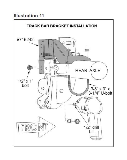
Using the existing hole in the outboard face of the Superlift track bar bracket as a template, use a centering punch to mark hole center. Drill a 1/2” hole through the outboard side of the factory track bar bracket. After drilling, file smooth any burrs and sharp edges then paint the exposed metal surfaces. Install the supplied 1/2” x 1” bolt, flat washer, Stover nut, as shown. Tighten (57).
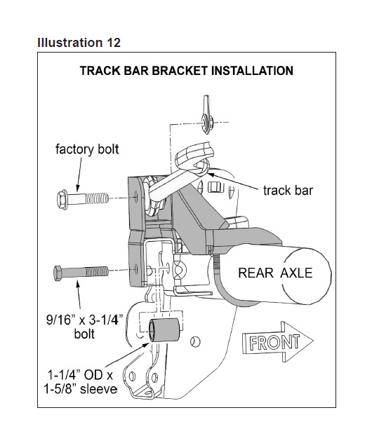
34) TRACK BAR… [Illustration 12]
Insert the supplied 1-1/4” OD x 1-5/8” sleeve inside the factory track bar mount. Install the supplied 9/16” x 3-1/4” bolt through the Superlift bracket, factory mount, and sleeve then secure using the supplied washer and tab nut (#12- 5700) (82).
Reconnect track bar using factory hardware. The bar will be tightened in a later step.
35) BRAKE HOSE BRACKETS…
NOTE: If optional Bulletproof brake hoses are being used, these brackets are not required.
Perform this step one side at a time.
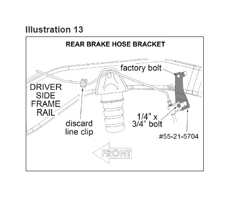
A plastic clip, shown in [Illustration 13], attaches the metal brake line to the frame; remove and discard this clip.
Attach the rear brake hose bracket (#55-21-5704 driver side and #55-22-5704 passenger side) to the factory frame location using the factory hardware. Be sure the alignment tab engages with the hole in the frame, as shown. Tighten (95 in-lb).
Attach the brake hose-to-bracket using the supplied 1/4” x 3/4” bolt, washer, and Nyloc nut. Install bolt from the outside, place the washer on the nut side then tighten (95 in-lb).
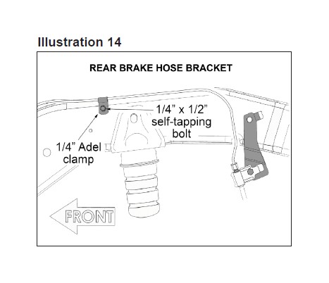
[Illustration 14] Carefully re-form the metal line so that it runs along the upper edge of the frame, as shown. The supplied Adel clamps (one per side) hold the re-formed metal brake lines snuggly against the frame to prevent them from potentially making contact with the sway bar links.
36) PARKING BRAKE CABLES, 2-DOOR MODEL ONLY…
The parking brake cables are routed beneath the vehicle body (along the transmission tunnel), above a frame crossmember then down to each wheel. On each side, disconnect the cables at the axle and re-route them to below the frame crossmember. Reattach cables-to-axle.
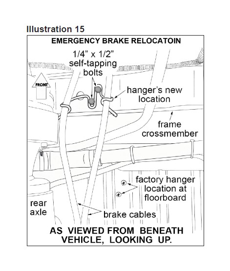
37) PARKING BRAKE CABLES, 4-DOOR MODEL ONLY… [Illustration 15]
The parking brake cables are routed beneath the vehicle body (along the transmission tunnel), above a frame crossmember, then through a wire hanger bracket that is attached to the floorboard. Detach the two parking brake cables from the wire hanger bracket then detach the wire hanger bracket from the floorboard.
Position the wire hanger bracket at the center of the frame crossmember, as shown. Using the wire hanger bracket as a template, mark the location for the two mounting holes to be drilled. Drill the mounting holes using a 13/64” bit. Attach the wire hanger bracket-to-frame crossmember using the supplied 1/4” x 1/2” self-tapping bolts and tighten (75 in-lb).
On each side, disconnect the parking brake cable at the axle and re-route them to below the frame crossmember. Insert each parking brake cable into the relocated wire hanger bracket then reconnect parking brake cables-to-axle.
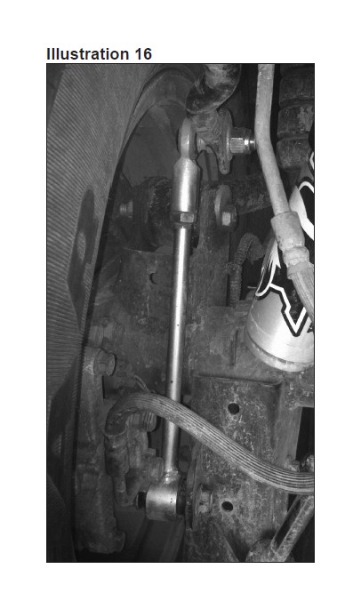
38) SWAY BAR LINKS… [Illustration 16]
Drill out the holes in the ends of the sway bar to 1/2”.
Lubricate the supplied bushings and sleeves with a light, Silicone or Lithium based grease; then install 3/4” ID bushings and 1/2” ID sleeves into the bottom (eyeing) end of the Superlift sway bar links (#55-32-5704).
Apply anti-seize to the top (stud) end of the Superlift sway bar links. Install the 1/2” jam nut onto the link then the 90° swivel end. Adjust the swivel end to reach a center of swivel-to-center of eye length of 11-1/4” then tighten the jam nut.
From the factory, the sway bar links mount outboard of the sway bar body with their upper studs facing inboard. The Superlift links install facing the same direction as factory.
First position one 1/2” SAE washer onto the link stud, then insert stud through the sway bar body attachment hole. Position remaining 1/2” SAE washer, Nyloc nut and tighten (80).
Attach the Superlift links’ lower ends using the factory hardware. Tighten (75).
39) SHOCK ABSORBERS…
Install shock absorbers. If using Superide shocks the shock body should be bolted to the axle with the shaft mounted to the frame. The Fox shocks come with the hardware installed so the body mounts to the frame and the shaft to the axle. Install the factory lower shock bolts and nut; do not tighten at this time. At this time, tighten only the upper shock mount bolts (37). Apply shock decals.
IF VEHICLE IS 2 DOOR OR 2007-2011 PROCEED TO STEP 41.
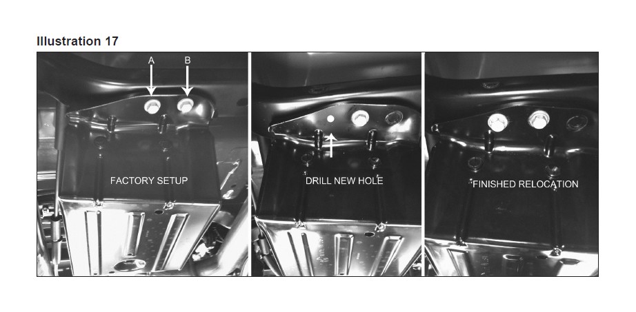
40) EVAPORATIVE CANISTER…Located on the driver side between the transfer case and rear axle.
Loosen the rear single bolt of the evaporative canister but do not remove.
[Illustration 17] Remove the front two bolts. Measure from the center of the inside hole “A” towards the center of the vehicle 2”, then to the rear of the vehicle 9/16”, mark and drill a 5/8” hole.
Pivot the evaporative canister to the driver side of the vehicle so the hole “A” is now over the “B” position and reinsert the factory bolt. (75)
Insert the remaining factory bolt trough the newly drilled hole. (75) Tighten the rear bolt. (75).
FINAL PROCEDURES
41) TIRES / WHEELS…
Tighten the lug nuts (115) in the sequence shown in illustration 9.
WARNING: When the tires / wheels are installed, always check for and remove any corrosion, dirt, or foreign material on the wheel mounting surface, or anything that contacts the wheel mounting surface (hub, rotor, etc.). Installing wheels without the proper metal-to-metal contact at the wheel mounting surfaces can cause the lug nuts to loosen and the wheel to come off while the vehicle is in motion.
WARNING: Retighten lug nuts at 500 miles after any wheel change, or anytime the lug nuts are loosened. Failure to do so could cause wheels to come off while vehicle is in motion.
42) INITIAL CLEARANCE CHECK, REAR…
With the vehicle still on jack stands, and the suspension “hanging” at full extension travel, check all components for proper operation and clearances. Pay special attention to clearance between the tires / wheels and brake hoses, driveshaft, etc.
43) HARDWARE TIGHTENING SEQUENCE…
Remove jack stands and lower vehicle to the floor. The suspension is now supporting vehicle weight.
Rear track bar, both ends (125).
All rear control arms-to-frame and axle (125).
Front / lower control arms-to-frame and axle (125). NOTE: Be sure that eccentric cam bolts are positioned as per installation step.
Front / upper control arms-to-frame and axle (75).
All shock absorber eyes (56).
44) FRONT TRACK BAR ADJUSTMENT…
Verify that the tires (not the steering wheel) are pointed straight ahead. Position a plumb bob, or similar tool, against the inside edge of the frame. Measure the distance between the line of the plumb bob and the inside edge of the wheel. Record this measurement, then repeat the procedure on the other side.
Compare the two measurements; the goal is to make them equal. If the driver side measurement is greater than the passenger side, the track bar needs to be lengthened. If the passenger side measurement is greater than the driver side, the track bar needs to be shortened.
Disconnect the lower (adjustable) end of the track bar from the axle and make the appropriate adjustments.
Tighten the jam nut firmly then reattach the bar-to-axle (130). Tighten the bar-to-frame bolt (130). WARNING! No more than 3/8” of Heim end threads can be exposed once the jam nut is tightened.
45) CENTER THE STEERING WHEEL…
IMPORTANT: The steering wheel must be centered prior to moving the vehicle, or an Electronic Stability Program sensor may be activated resulting in a dash light and a warning chime that requires 20 plus ignition key cycles to clear.
Start engine and steer wheels straight ahead. Loosen the nuts on the drag link adjustment sleeve then rotate adjuster until steering wheel center is achieved.
IMPORTANT - In order to achieve proper adjustment sleeve clamping force, clamp / bolt assemblies (found on the drag link and tie rod assemblies), the open side of each clamp must align with the slot in the threaded adjustment sleeve. Improper positioning and bolt torque will promote linkage deflection, which may contribute to tire shimmy. Tighten clamp bolts (26).
46) FINAL CLEARANCE and TORQUE CHECK...
Cycle steering lock-to-lock and inspect the tires / wheels, and the steering, suspension, and brake systems for proper operation, tightness and adequate clearance.
47) HEADLIGHTS...
Readjust headlights to proper setting.
48) ALIGNMENT...
Realign vehicle to factory specifications. A precise alignment, including the centering of the steering wheel, is required in order for the vehicle’s Electronic Stability Program to function properly. A laser alignment is recommended.
49) SUPERLIFT WARNING DECAL…
The WARNING TO DRIVER decal installs on the inside of the vehicle within the driver’s view. Prior to installation, pre-clean the surface with the supplied alcohol cleaning pad.
50) SUPERLIFT BADGES...
This kit is packaged with a Superlift badge. Prior to installation, use the supplied alcohol pad to eliminate all soap and or other non-adhering residues that may impair adhesion, thoroughly clean the entire area of placement.
Remove the adhesive back and place small badge in the desired location. The adhesive on our badges is pressure sensitive and must be applied using pressure on all areas of the graphic. Like any PSA (pressure sensitive adhesive), it can take up to 72 hours for the adhesive to fully cure. Once the badge is in place do not peel it up, this will diminish the adhesive properties and could result in damaging the badge itself
To keep your Superlift badge in “like new” appearance keep the badge free/clear of solvents and chemicals that could cause the adhesive to dry or dissolve. This includes gasoline, diesel fuel, paint thinner, and alcohol. Soap and water is all that is needed for cleaning. Degreasers can be used sparingly and hand wiped/applied if needed, although not suggested.
