FREE 1 to 3-Day Delivery on Orders $149+ Details

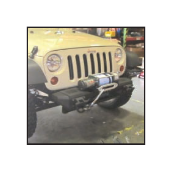
How to Install Rugged Ridge XHD Aluminum Front Bumper Winch Plate on your 07-18 Jeep Wrangler JK; 2018 Jeep Wrangler JL

Shop Parts in this Guide
Contents:
1. Winch Plate (1)
2. Nut plate (2)
3. M10 Hex Bolts (2)
4. M10 Flat Washers (2)
Note: Bumper will need to be removed if previously installed.
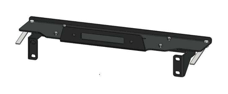
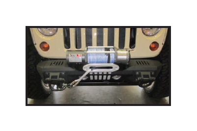
1. Install the winch plate on top of the frame horns behind the front mounting plates. Fit winch plate snug to the backside of the frame bumper mounting plates.
2. Insert the nut plate into the top hole of the frame. Nut should be on the bottom side of the plate. Repeat for opposite side.
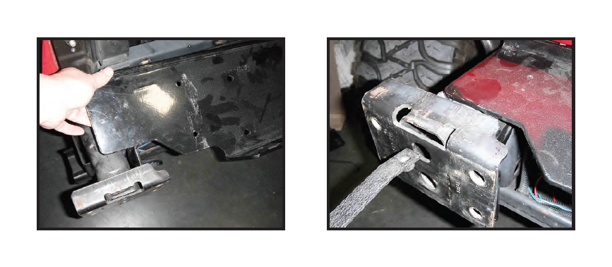
3. Insert a M10 hex bolt and M10 washers thru the hole of the winch plate and frame threading into the nut plate. Tighten. Repeat for opposite side.
4. Install bumper. Refer to bumper mounting instructions.
Contents:
(1) “L” Relocation Bracket
(1) M6-1.0x20 Hex Head Bolt
(1) M6-1.0x30 Hex Head Bolt
(4) M6 Flat Washer
(2) M6 Nylock Nut
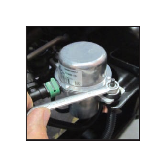
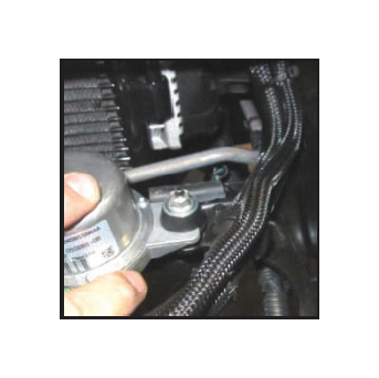
Step 1: Unbolt vacuum pump from factory mounting bracket. Save factory M6 nut. It will be reused later.
Step 2. Remove front bushing from pump and flip over as shown. Tall side will need to face up. Reinstall bushing.
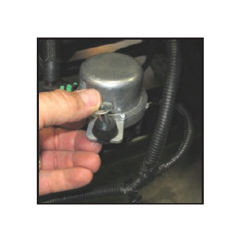
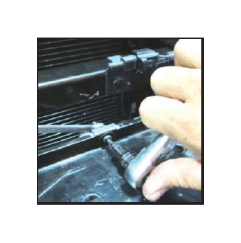
Step 3: Rotate pump as shown. Front mounting tab will be relocated to factory rear mounting stud.
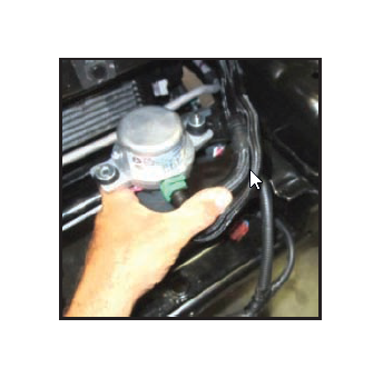
Step 4: Secure pump to rear factory stud using M6 nut removed in step #1.
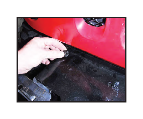
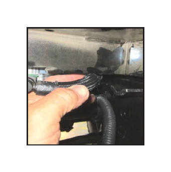
Step 5: Disconnect small air line and wire harness. move harness and hose to the front of pump. Reconnect.
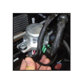
Step 6: If needed a Zip Tie can be used to pull air lines together.
Step 7: Attach “L” bracket to pump using longer M6 hex bolt flat washer, and Nylock nut.
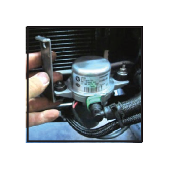
Step 8. Push pump back and slide winch plate onto vehicle. If winch plate does not have a pre-drilled hole, mark location of “L” bracket and remove plate.
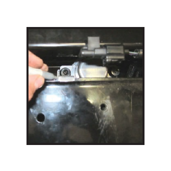
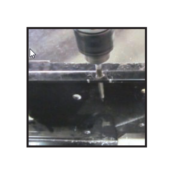
Step 9: With plate removed from frame and mounting hole marked drill 1/4” hole into winch plate. Apply black paint to exposed metal.
Step 10: Reinstall winch plate and secure “L” bracket. Tighten all hardware.
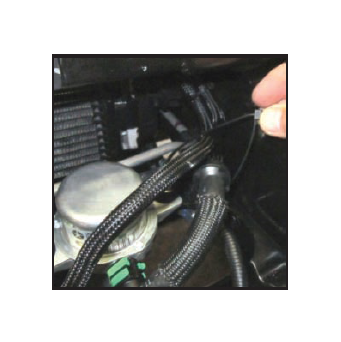
Step 11: Inspect all air lines and wires. If needed Zip Ties can be used to position lines away from plate.
Step 12: Install winch plate using 11541.13 instructions. Install aluminum bumper.