FREE 1 to 3-Day Delivery on Orders $149+ Details

How to Install Sprintex 3.6L CUR Intercooled Supercharger System with Tuner on your Wrangler
Installation Time
1 days
Tools Required
- Metric & inch spanners (wrenches) and sockets
- Flat blade & Philips screwdrivers
- Cloth tape (race tape or 100MPH tape)
- Trim clip removal tool
- Pliers & side cutters (dykes)
- ½” Breaker bar
- Hose clamp pliers
- Rubber grease or white petroleum jelly
- Metric Allen keys
- ½” Drive short extension
- Torque wrench
- Electrical tape
PARTS SUPPLIED
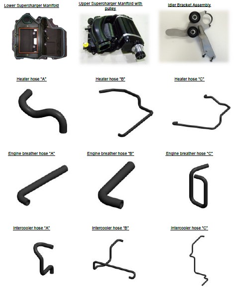
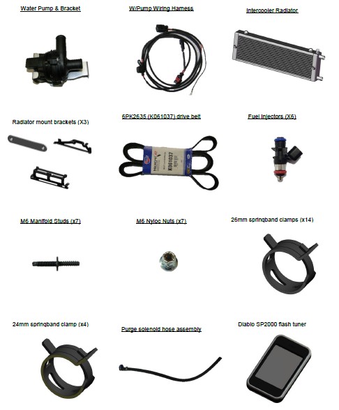
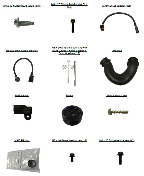
PENTASTAR 3.6L V6 JEEP JK SUPERCHARGER SYSTEM
SECTION 1
DISASSEMBLY INSTRUCTIONS
PREPARATION
Ensure that all components required to install the supercharger system are available, refer to the Parts Supplied section provided earlier.
Ensure that all required tools are available.
Please read the entire installation manual prior to beginning the installation procedure.
Ensure the vehicle is located in a secure position with vehicle tyres secured and hand brake applied. To avoid injury, Sprintex® recommends the use of a suitable vehicle lift or appropriate safety stands when the vehicle is required to be lifted. Stands should be positioned as per the vehicle manufacturer’s owner’s handbook.
SAFETY WARNING
No unauthorised service or alteration may be undertaken to the Sprintex supercharger. Installation should be carried out in a workshop which is a safe and ventilated working environment with equipment and procedures compliant with local authority guidelines and legal requirements. Installers should ensure adequate hearing, eye, and physical protection is used at all times during the installation process. Installers should take reasonable precautions to avoid fatigue and closely follow the installation instructions during every installation. Sprintex recommends installation should not be carried out unsupervised. Sprintex, its directors, employees and agents will not accept liability for damage, accident or injury resulting from the installation process. Safety warnings are also provided throughout this document.
Allow engine to cool prior to proceeding with disassembly to prevent scalding.
NOTES:
During disassembly and removal of components, take notes and ensure parts are labelled and stored safely; this will help with the reassembly.
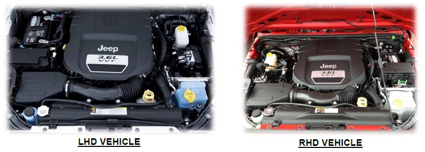
Many of the photos shown in this document are of a typical Jeep- JK right hand drive vehicle and are similar to a typical Jeep- JK left hand drive vehicle.
Connect and disconnect battery cables, jumper cables or battery charger only with the ignition off.
Disconnecting the battery may erase fault codes stored in control module memory.
Using diagnostic equipment, check for fault codes before disconnecting battery cables.
If the malfunction indicator light (MIL) is illuminated.
MIL (Malfunction Indicator Lamp) light.
The MIL light can be found in one of two locations, dependant on the market the vehicle has been built for.
The MIL light may be an illuminated ENGINE symbol within the instrument cluster.
Please refer to the Jeep owner’s handbook to define which off the above applies to the vehicle to be fitted with the Sprintex unit.
Always disconnect the negative battery terminal first. This prevents possible shorting and potential battery damage.
1. Load the ECM re-flash
Read the instructions included with the Diablo SP2000 flash tuner.
Follow the instructions included with the Diablo SP2000 flash tuner.
2. Fuel System Pressure Relief
Remove the fuel fill cap.
Remove the fuel pump fuse (M37, 10A fuse labelled ABS, FUEL PUMP RELAY, SWAY BAR) from the Power Distribution Centre (PDC). For location of the fuel pump fuse, refer to label on the underside of the PDC cover
Start and run the engine until it stalls.
Attempt restarting the engine until it will no longer run.
Turn the ignition key to the OFF position.
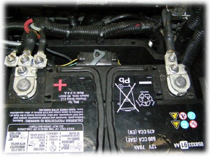
Disconnect and isolate the negative (“-“) battery terminal.
Re-install the fuse.
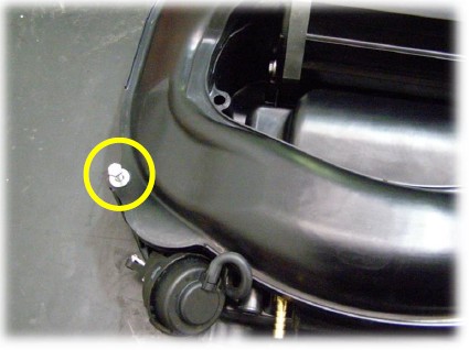
3. Remove the front bumper.
Remove the push pin fasteners (2) and release the splash shield (1) from the bumper.
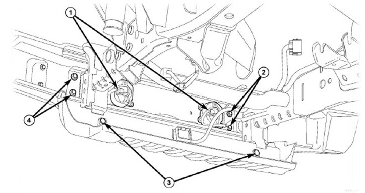
Remove the push pin fasteners (3) and remove the splash shield.
Disconnect the electrical connectors (1).
Remove the outer (4) and inner support bolts (2) and remove the front bumper.
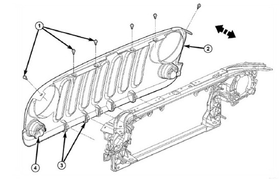
4. Remove the grille.
Twist the centre of the push pin insert to release and remove the six push pin fasteners (1)
Release the lower clips (3) and separate the grille from the front end module.
Disconnect the electrical connectors (4).
5. Drain cooling system.
NOTE: Radiator drain valve is located on the right/lower side of radiator facing to front of vehicle.
Remove radiator pressure cap from radiator or coolant recovery container as necessary.
Attach one end of a hose to the drain valve. Put the other end into a clean container. Open valve and drain coolant from radiator.
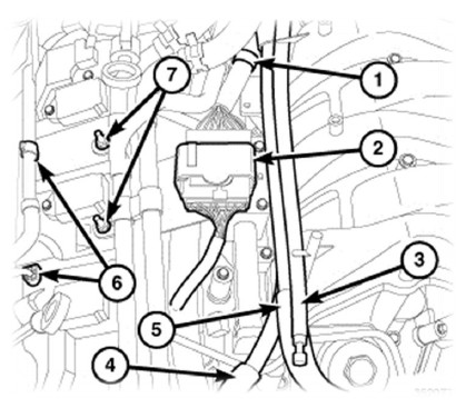
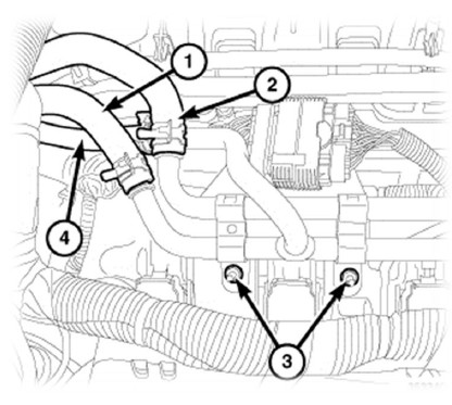
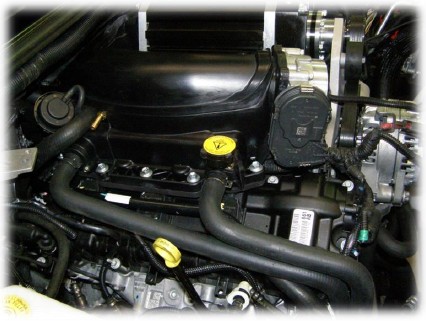
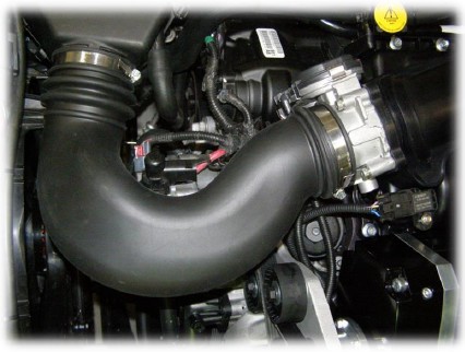
6. Intake manifold removal.
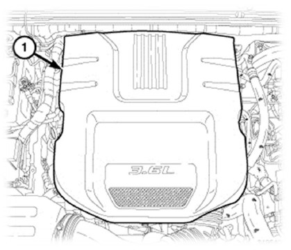
Remove the engine cover (1).
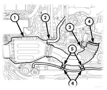
Disconnect the electrical connector (3) from the Inlet air temperature (IAT) sensor, remove the sensor from the inlet pipe and set it aside to use later.
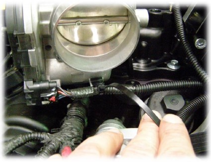
Loosen the clamp (4) at the throttle body.
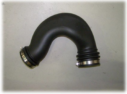
Disconnect the fresh air makeup hose (2) from the air cleaner body.
Disengage the coolant hose from the two retainers (6).
Remove the two bolts (5) from the air inlet hose.
Disengage the air inlet hose from the throttle body and pull the air cleaner body (1) straight up off of the three locating pins.
Disconnect the electrical connectors from the Manifold Absolute Pressure (MAP) sensor (1) and the Electronic Throttle Control (ETC) (6).
Disengage the ETC harness from the clip (5) on the throttle body.
Disengage the wire harness retainer (2) from the upper intake manifold.
Disengage the wire harness retainers (3 and 4) from the left front upper intake manifold support bracket and reposition the wire harness.
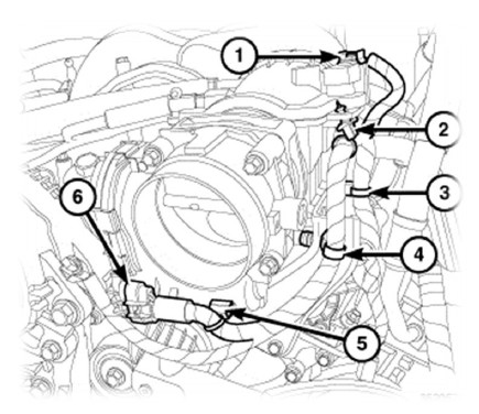
Disconnect the following hoses from the upper intake manifold:
Positive Crankcase Ventilation (PCV) (1)
Fuel vapour purge (3)
Brake booster (2)
Remove two nuts (2), two bolts (3) and the left front upper intake manifold support bracket (1).
Note: this bracket will not be used for the supercharger install, store it along with the other OEM components.
Remove two nuts (2) from the left rear upper intake manifold support bracket (1)
Loosen two stud bolts (3) and reposition the left rear upper intake manifold support bracket (1) away from the upper intake manifold.
Note: Installing the upper manifold assembly is easier with this bracket removed and re-fitted subsequently.
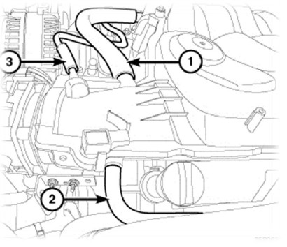
7. Disengage and reposition the following hoses from the upper intake manifold:
Transfer case vent (3)
Positive crankcase ventilation (PCV) (5)
Fresh air make up.(4)
Disengage the wire harness connector retainer (2) from the right upper intake manifold support bracket.
Disengage two purge tube retainers (6) from the right side upper intake manifold support bracket.
Remove two nuts (7).
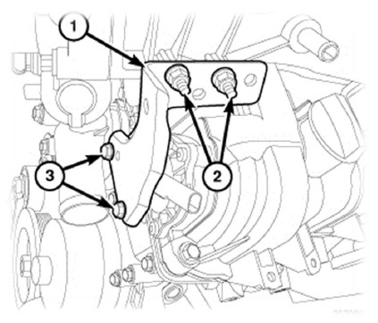
8. Remove the heater coolant tube assembly.
Remove the heater core supply hose (1) from the heater core tube assembly.
Remove the heater core return hose (2) from the heater core tube assembly.
Remove the heater core supply hose (2), heater core return hose (1) and oil cooler return hose (4) from the heater core tube assembly.
Remove two nuts (3) and the heater core tube assembly from the right upper intake manifold support bracket.
NOTE: Heater coolant tube assembly not shown for clarity
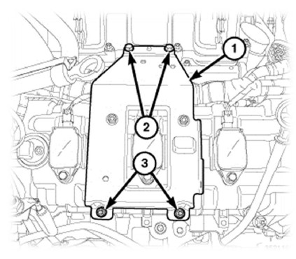
Remove two bolts (2) from the right upper intake manifold support bracket (1)
Remove two nuts (3) and the right upper intake manifold support bracket (1).
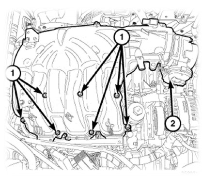
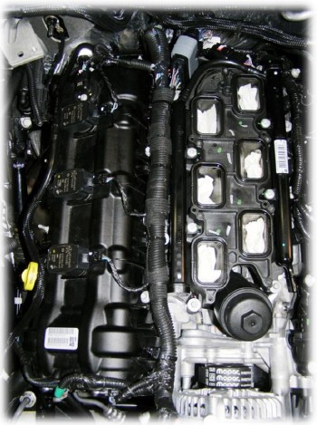
NOTE: The upper intake manifold attaching bolts are captured in the upper intake manifold. Once loosened, the bolts will have to be lifted out of the lower intake manifold and held while removing the upper intake manifold.
Remove seven upper intake manifold attaching bolts (1) and remove the upper intake manifold (2).
Cover the open intake ports to prevent debris from entering the engine.
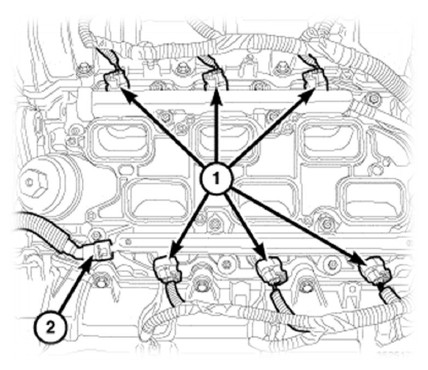
9. Remove the fuel rails and injectors.
Disconnect the fuel injector electrical connectors (1).)
Place a rag under the fuel rail supply line quick connector to catch any residual fuel while disconnecting the fuel supply hose (2) from the fuel rail.
Note: Fuel may escape under pressure when any fuel hose is disconnected. Take care to avoid contact with the skin or eyes. Ensure that no ignition source is close by to prevent the risk of fire.
Disconnect the fuel supply line quick-connect fitting at the fuel supply line.
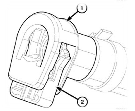
This type of quick-connect fitting is equipped with a redundant latch (2) and a single push button (1) that releases two internal latches located in the quick-connect fitting. Special tools are not required for removal.
CAUTION: Do not pry or pull up on the push button as damage to the latches of the quick-connect fitting will occur.
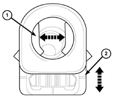
Pull the redundant latch (2) out away from the quick-connect fitting.
Press on the push button to release the internal latches (1) and remove the quick-connect fitting from the fuel system component.
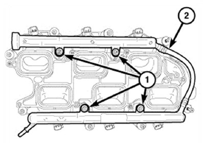
Remove the four bolts (1) from the fuel rail (2).
CAUTION: When removing the fuel rail from the lower intake manifold, one or more fuel injectors may remain in the intake manifold resulting in residual fuel spilling out onto the engine from the fuel rail.
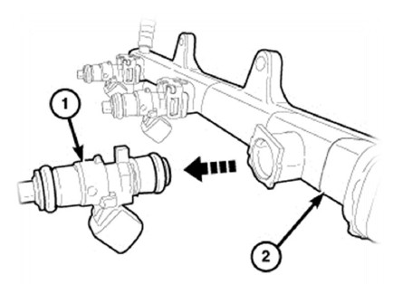
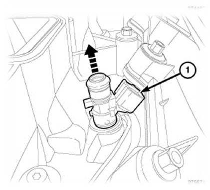
Remove the remaining fuel injectors (1) from the fuel rail (2).
Remove the remaining fuel injectors (1) from the lower intake manifold.
Lubricate the o-rings of the injectors supplied with the system with rubber grease or white petroleum jelly prior to replacing the OEM injectors. Take care when installing the injectors into the fuel rail to prevent damage to the o-ring.
Re-attach the fuel rail with the OEM fasteners and tighten to 7Nm.
Re-connect and lock the fuel injector electrical connectors.
Lubricate the fuel rail spigot with rubber grease or white petroleum jelly before reconnecting the fuel rail supply line quick connector.
Lock the connector.
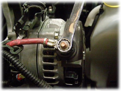
10. Remove the alternator and mounting bracket.
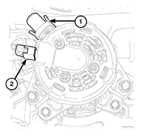
Remove the alternator electrical connector (2) and the B battery stud cover (1)
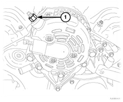
Remove the B retainer (1) and position aside the B cable.
Remove the alternator and mount via the 2 bolts either side of the alternator and the 2 lower screws in the lower section of the alternator mount bracket.
Remove the factory drive belt and replace with the belt supplied with the supercharger system.
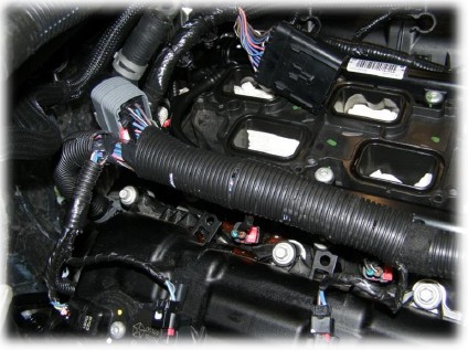
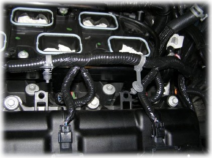
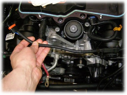
11. Modify the wiring harness.
Remove the harness retainers from the valve cover.
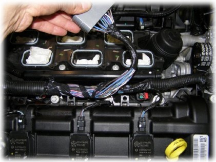
Disconnect the grey engine wiring harness connector.
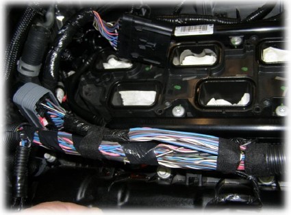
Carefully strip back the OEM harness until there is sufficient length available in the break-out wire to allow the grey plug to reach the back of the engine. Fold back the wiring and tape into place.
Ensure that all wiring is covered with protective sleeving and neatly taped into place.
Securely attach the harness to the valve cover using the cable ties supplied.
Failure to correctly protect the wiring loom may cause electrical faults in the future with short circuits due to insufficiently protected and unsecured wiring.
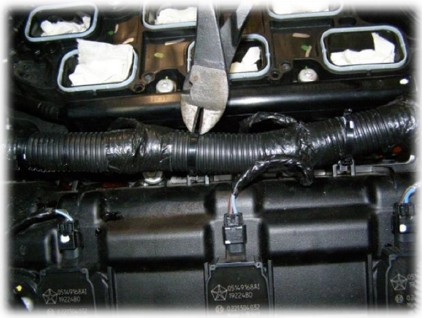
Remove the grey harness retainers from the valve cover and harness on the left bank, neatly tuck the harness down beside the fuel rail and tie in place with the cable ties supplied.
At this stage connect the water pump wiring harness to the injector connector of cylinder #2 and run the wire down beside the radiator. Tie in place with cable ties supplied.
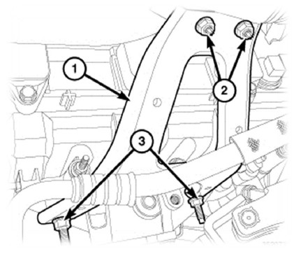
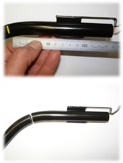
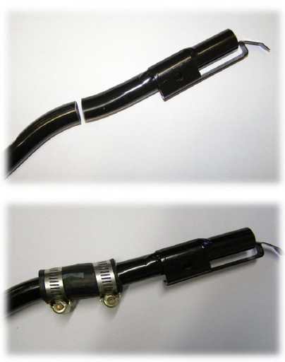
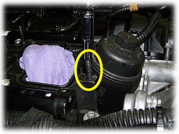
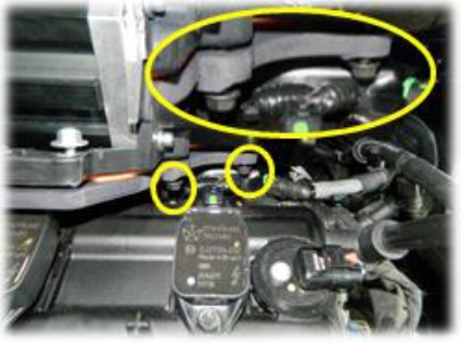
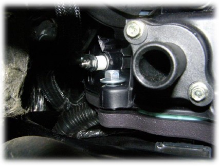
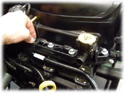
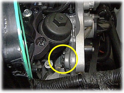
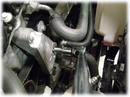
12. Modify the automatic transmission dipstick tube.
(Not required for manual transmission)
Remove the 2 bolts retaining the tube, one at the rear of the engine block and the other at the transmission. Remove the transmission dipstick tube. ( See Images)
Measure 135mm from the top of the dipstick tube and mark the tube, then cut the tube square along the mark.
Clean edges and remove burrs.
Rotate the end of the tube 180°.
Join the 2 sections of tube with the section of rubber hose and 2 hose clamps provided, making sure to push both ends together prior to tightening the hose clamps.
Re install the dip stick tube
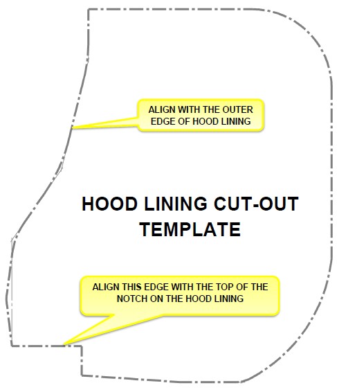
13. Modify the hood lining.
Remove the hood lining
Using the template supplied on the last page of this document, trace around the template and cut out area with a sharp pair of scissors.
Re-attach the hood lining.
Note: the reason for the cut out is to prevent the hood lining blocking the air box inlet.
PENTASTAR 3.6L V6 JEEP JK SUPERCHARGER SYSTEM
SECTION 2
INSTALLATION INSTRUCTIONS
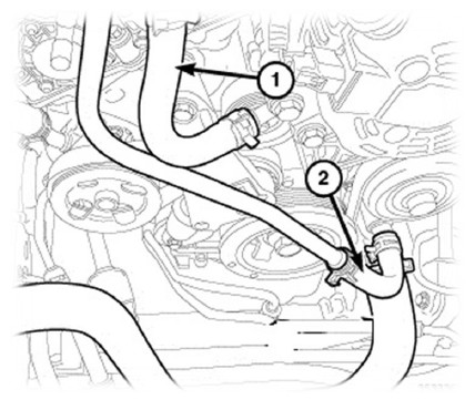
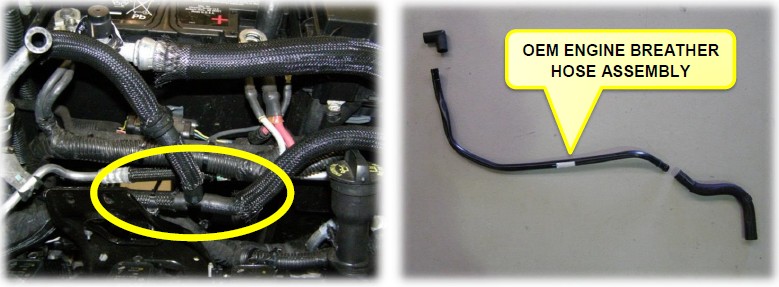
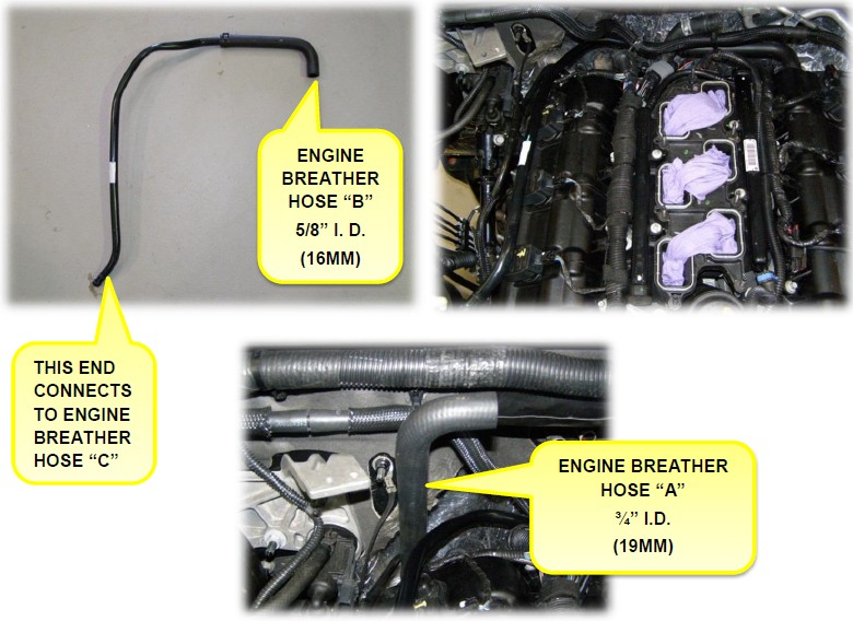
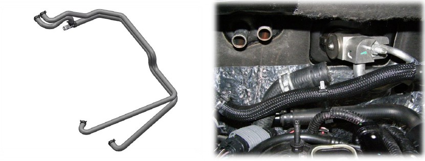
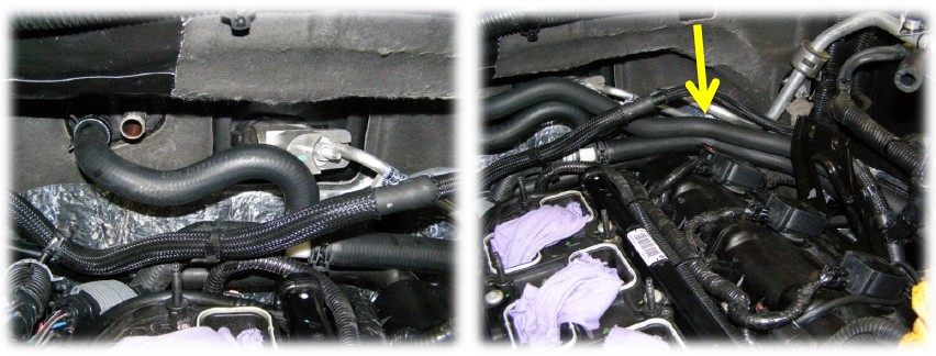
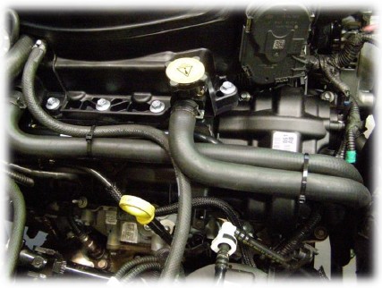
14. Install engine breather hoses.
Modify the vacuum hose routing, carefully separate the 2 ends of the hose at the “T” junction, rotate the “T” piece 180° and re-attach the hose ends as shown in image.
Remove the engine breather hose from the OEM intake manifold and remove both rubber ends from the rigid plastic line.
Attach the engine breather hose “B” (5/8” I.D).to the rigid plastic line (see Image).
Install the rigid plastic line and attach engine breather hose “B” to the spigot on the back of the RHS valve cover.
Attach the straight end of engine breather hose “A” to the spigot of the rear of the LHS valve cover.
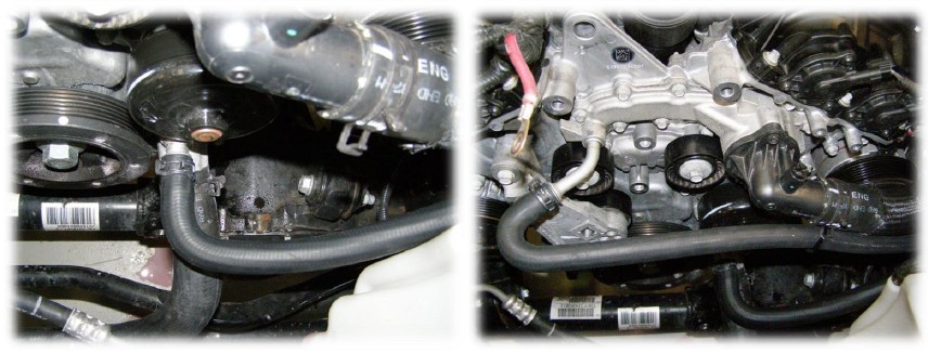
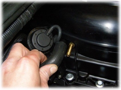
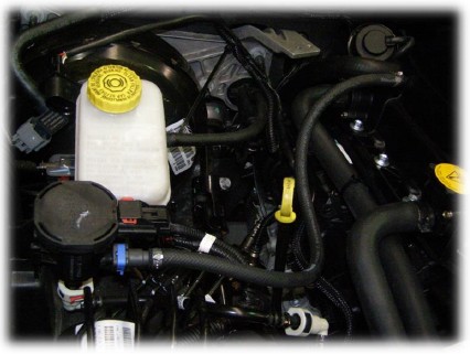
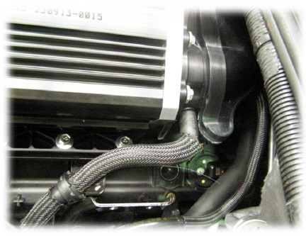
15. Install heater hoses.
Install the new heater hose assembly supplied. Neatly route the hoses as shown in the images below and connect the hose to the outlet on the engine block with the spring band clamps supplied.
Install the second heater hose, following the routing of the first hose and attach hose to the other spigot on the cylinder block with the spring band clamps supplied (see image).
Fix the hoses in place with 2 cable ties supplied.
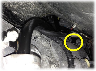
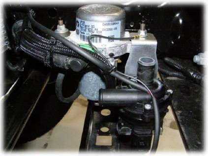
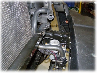
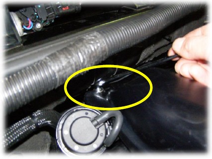
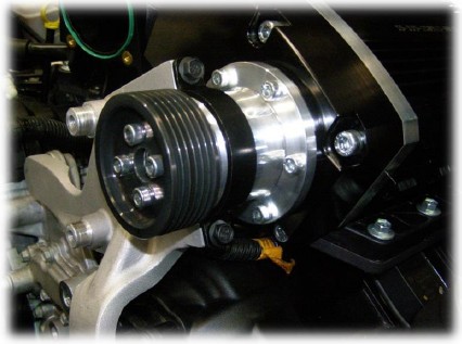
16. Install the water pump bracket.
Attach the water pump bracket and pump to the OEM vacuum pump mount behind the front bumper bar. Fasten the bracket in place with the original nuts; also connect the pump connector and the ground connection eyelet.
Fix the harness in place with the cable ties supplied.
NOTE: If the vehicle is fitted with a non genuine bumper, you may need to relocate the water pump bracket and reroute the intercooler hoses to suit the vehicles aftermarket options.
17. Install the Intercooler hoses.
Attach intercooler hose “A” to the water pump and fix in place with a spring band clamp supplied.
Install intercooler hose “B”. Route the hose through the gap on the upper LHS of the radiator shroud and pass the hose down beside the radiator then back toward the engine.
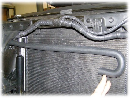
Lower intercooler hose “C” down behind the radiator following the OEM radiator hose routing, bring the lower section of the intercooler hose forward and connect the end of the hose to the water pump using the spring band clamp supplied. Fix hoses in place with the cable ties supplied.

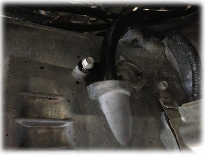
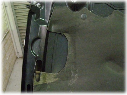
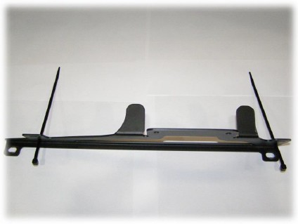
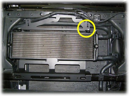
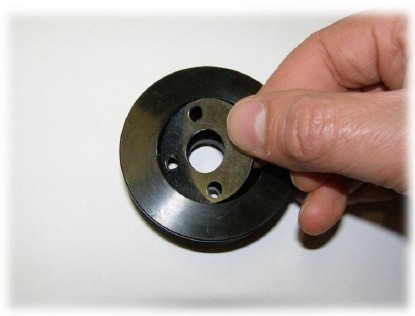
18. Install the radiator mount brackets and radiator.
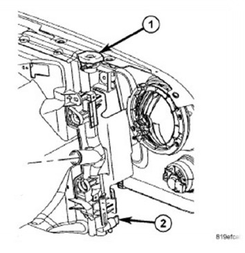
Feed the radiator mount nut plate into the hood latch hole underneath the radiator support frame. (See image).
Prior to attaching the upper radiator mount bracket, feed 2 cable ties through the holes in the bracket, attach the bracket to radiator support frame with the M6 X 16mm SHCS and the nut plate, do not tighten until radiator has been installed.
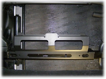
Attach the lower radiator mount bracket by pushing it onto the lower radiator support frame, making sure that he slots are lined up with the corresponding slots of the radiator support frame.(see image)
Prior to installing the radiator to the vehicle, install the ¼ BSPP plug into the radiator and tighten to 16Nm. (see lower right image )Then attach the radiator to the upper radiator mount bracket with the M8 X 12mm hex head screws; tighten the upper radiator mount bracket.
Attach the hoses to the radiator with the spring band clamps supplied and tighten all fasteners and cable tie the hoses in place.
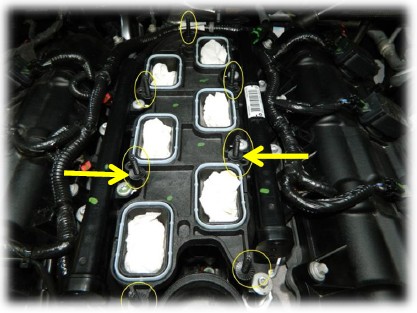
19. Install the lower supercharger manifold.
Install the 7 manifold studs with a 4mm socket and tighten to 8NM.for stud location. Note that the 4 central studs utilise the inboard location. See images below for clarification.
Place the four M6 X 25mm black screws into the lower manifold from the underside (see image). Retain screws in place with M6 Nyloc nuts, finger tighten only.
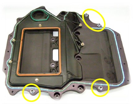
Place the lower manifold over the studs & install the M6 Nyloc nuts utilising the four nuts which are retaining the four M6 x 25mm black screws in place.
Take care to not drop any nuts down the intake ports.
Gently push the lower manifold back towards the bulk head and tighten the nuts to 12Nm.
Attach the throttle body extension loom and MAP sensor adaptor loom, lay the extension toward the left hand side of the vehicle.
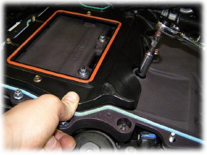
20. Install the upper supercharger manifold.
Prior to installing the upper assembly apply 3 strips of cloth tape to the bulkhead insulation to prevent damage to it when tightening the rear fasteners on the upper manifold (see mage below).
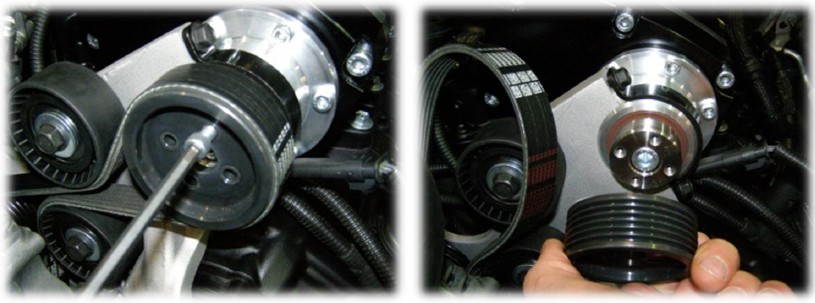
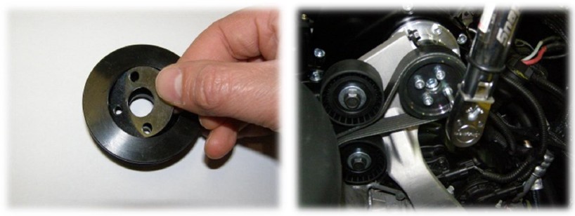
Install a 1mm shim into the back supercharger drive pulley and attach it to the supercharger with the four M6 x 20mm SHCS and tighten to 12Nm.
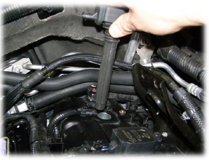
Remove cylinder #6 coil.(see Image)
Place the M6 X 90mm long hex head screw and washer supplied into the upper manifold prior to installation; carefully lower the upper manifold onto the lower manifold.
With the upper manifold in place, start to tighten the rear screw but do not tighten completely.
21. Tighten the upper manifold
Place the ten M6 X 30mm flange head screws into the upper manifold and finger tighten only.
Place the M6 x 100 hex head screw and washer into bolt hole #4.
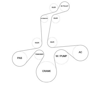
Follow the sequence below for tightening the fasteners. Tightening of the 2 screws under the rear of the supercharger manifold (1 & 2 in the diagram) is somewhat difficult and will require some patience in getting these tight. Tighten these 2 screws completely before proceeding with the rest of the manifold screws.
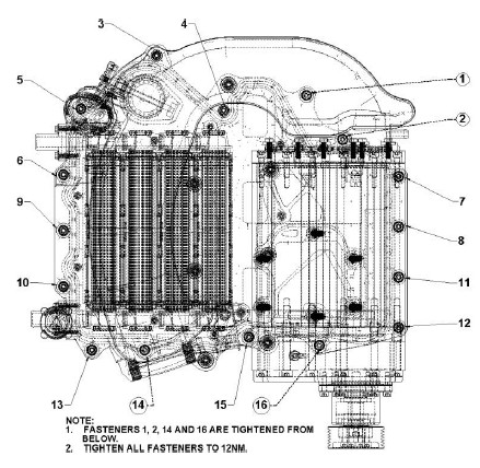
Make sure all screws have been tightened screws to 12Nm.
Install #6 cylinder coil, and tighten fastener to 8Nm.
Connect and lock the coil electrical connector.
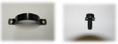
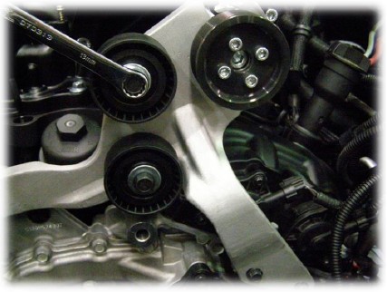
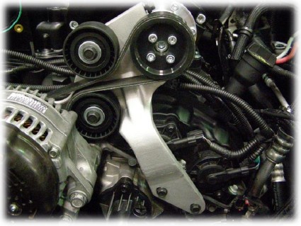
22. Install the idler pulley bracket
Loosely attach the idler bracket to the supercharger drive extension using the strap and two M6 x 12mm screws.
Attach the bracket to the block with two M6 x 20mm hex screws.
Attach the rear post of the idler bracket to the cylinder block with the M6 x 12mm screw and washer
Tighten all fasteners to 12Nm.
Attach the idler pulleys to the bracket with two M8 x 16mm screws and two 8.5mm x 25mm x 3mm washers, and tighten to 23Nm.
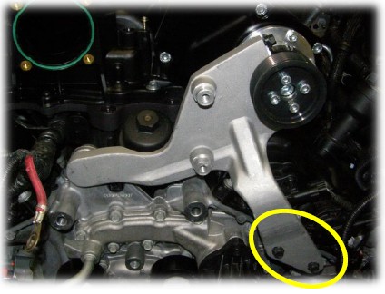
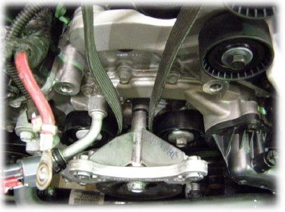
23. Install the drive belt
Install the new drive belt and re-attach the alternator and bracket making sure to feed the drive belt either side of the post on the back of the alternator mount bracket. (See image) Note that the image shows the bracket separated from the alternator, to provide a clearer picture for the belt routing. It is not necessary to separate the alternator and bracket assembly.
Tighten the 2 top screws to 54Nm, Tighten the bottom 4 screws to 30Nm.
Attach the positive battery cable to the alternator and tighten to 13Nm. Re fit the insulating cover over the connection
Attach the alternator connector
Install the drive belt over the remaining pulleys. It will be necessary to relieve the tension on the belt tensioner, using a ½” breaker bar.
24. Install the throttle body
Prior to installing the throttle body remove the o-ring seal from the OEM manifold and fit it to the throttle body seal groove of the supercharger manifold.
Attach the throttle body to the manifold with the four M6 x 40mm SHCS and washers supplied.
Connect the throttle body extension loom to the throttle body and secure in place with the OEM harness clip and a cable tie supplied.
Connect the throttle body loom extension to the OEM throttle body connector.
Trim cable tie.
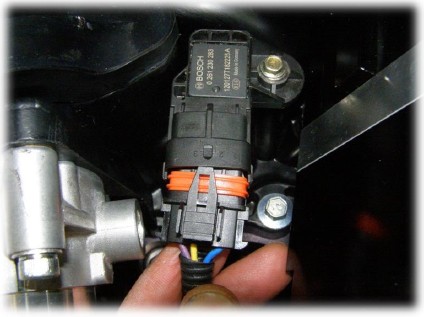
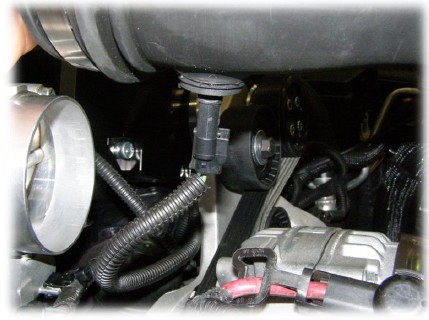
25. Install the MAP sensor
Prior to installing the MAP sensor, lubricate the o-ring with rubber grease or white petroleum jelly attach the MAP sensor to the manifold and secure in place with the self-tapping screw supplied and tighten to 6Nm.
Attach the MAP sensor adaptor to the MAP sensor.
26. Attach engine breather hose
Connect the engine breather hose to the manifold.
27. Attach intercooler hoses
Attach the intercooler hoses to the manifold and secure in place with the 26mm spring band clamps supplied.
28. Install the purge solenoid hose
Attach the EVAP purge solenoid hose to the supercharger manifold.
Connect other end of hose to the purge solenoid.
29. Install the air box
Install the air box and attach the engine breather hose “C”
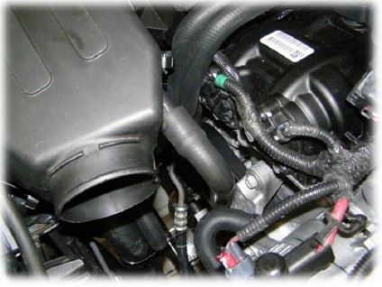
30. Install the clean air duct
Attach the hose clamps to the clean air duct.
Connect the intake air temp sensor (IAT) connector.
Attach the duct to the air box and throttle body, and tighten the hose clamps.
31. Attach vacuum hose
Attach the OEM brake vacuum hose to the supercharger manifold.
32. Secure hoses
Make sure all hose are secured with cable ties supplied.
33. Connect battery
Connect battery terminals and tighten to 7 Nm.
Note: Always connect the positive battery terminal before connecting the negative terminal to reduce the danger of short circuit through the wrench.
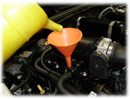
34. Fill intercooler cooling system.
Remove the intercooler fill cap and fill the system with approximately 1.9 litres of ethylene glycol based automotive engine coolant. Ensure all air is expelled from the system. Air in the intercooler system can reduce engine performance and cause pinging or detonation.
35. Refill the vehicles cooling system
Evacuating or purging air from the cooling system involves the use of a pressurized air operated vacuum generator. The vacuum created allows for a quick and complete coolant refilling while removing any airlocks present in the system components.
WARNING: ANTIFREEZE IS AN ETHYLENE GLYCOL BASE COOLANT AND IS HARMFUL IF SWALLOWED OR INHALED. IF SWALLOWED, DRINK TWO GLASSES OF WATER AND INDUCE VOMITING. IF INHALED, MOVE TO FRESH AIR AREA. SEEK MEDICAL ATTENTION IMMEDIATELY. DO NOT STORE IN OPEN OR UNMARKED CONTAINERS. WASH SKIN AND CLOTHING THOROUGHLY AFTER COMING IN CONTACT WITH ETHYLENE GLYCOL. KEEP OUT OF REACH OF CHILDREN. DISPOSE OF GLYCOL BASED COOLANT PROPERLY. CONTACT YOUR DEALER OR GOVERNMENT AGENCY FOR LOCATION OF COLLECTION CENTER IN YOUR AREA. DO NOT OPEN A COOLING SYSTEM WHEN THE ENGINE IS AT OPERATING TEMPERATURE OR HOT UNDER PRESSURE; PERSONAL INJURY CAN RESULT. AVOID RADIATOR COOLING FAN WHEN ENGINE COMPARTMENT RELATED SERVICE IS PERFORMED; PERSONAL INJURY CAN RESULT
WEAR APPROPRIATE EYE AND HAND PROTECTION WHEN PERFORMING THIS PROCEDURE.
NOTE: The service area where this procedure is performed should have a minimum shop air requirement of 80 PSI (5.5 bar) and should be equipped with an air dryer system.
NOTE: For best results, the radiator should be empty. The vehicle's heater control should be set to the heat position (ignition may need to be turned to the on position but do not start the motor).
Refer to the Chrysler Pentastar Service Equipment (Chrysler PSE) Coolant Refiller #85-15-0650 or equivalent tool's operating manual for specific assembly steps.
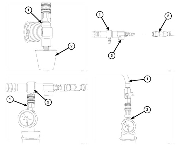
Choose an appropriate adapter cone that will fit the vehicle's radiator filler neck or reservoir tank.
Attach the adapter cone (2) to the vacuum gauge
Make sure the vacuum generator/venturi ball valve (3) is closed and attach an airline hose (2) (minimum shop air requirement of 80 PSI/5.5 bar) to the vacuum generator/venturi (1).
Position the adaptor cone/vacuum gauge assembly into the radiator filler neck or reservoir tank. Ensure that the adapter cone is sealed properly
Connect the vacuum generator/venturi (2) to the positioned adaptor cone/vacuum gauge assembly (1)
Open the vacuum generator/venturi ball valve.
NOTE: Do not bump or move the assembly as it may result in loss of vacuum. Some radiator overflow hoses may need to be clamped off to obtain vacuum.
Let the system run until the vacuum gauge shows a good vacuum through the cooling system. Refer to the tool's operating manual for appropriate pressure readings.
NOTE: If a strong vacuum is being created in the system, it is normal to see the radiator hoses to collapse.
Close the vacuum generator/venturi ball valve.
Disconnect the vacuum generator/venturi and airline from the adaptor cone/vacuum gauge assembly.
Wait approximately 20 seconds, if the pressure readings do not move, the system has no leaks. If the pressure readings move, a leak could be present in the system and the cooling system should be checked for leaks and the procedure should be repeated.
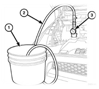
Place the tool's suction hose into the coolant's container.
NOTE: Ensure there is a sufficient amount of coolant, mixed to the required strength/protection level available for use. For best results and to assist the refilling procedure, place the coolant container at the same height as the radiator filler neck. Always draw more coolant than required. If the coolant level is too low, it will pull air into the cooling system which could result in airlocks in the system.
Connect the tool's suction hose (1) to the adaptor cone/vacuum gauge assembly (2).
Open the suction hose's ball valve to begin refilling the cooling system.
When the vacuum gauge reads zero, the system is filled.
NOTE: On some remote pressurized tanks, it is recommended to stop filling when the proper level is reached.
Close the suction hose's ball valve and remove the suction hose from the adaptor cone/vacuum gauge assembly.
Remove the adaptor cone/vacuum gauge assembly from the radiator filler neck or reservoir tank.
With heater control unit in the HEAT position, operate engine with container cap in place.
After engine has reached normal operating temperature, shut engine off and allow it to cool. When engine is cooling down, coolant will be drawn into the radiator from the pressure container.
Add coolant to the recovery bottle/container as necessary. Only add coolant to the container when the engine is cold. Coolant level in a warm engine will be higher due to thermal expansion. Add necessary coolant to raise container level to the COLD MINIMUM mark after each cool down period.
Once the appropriate coolant level is achieved, attach the radiator cap or reservoir tank cap.
36. Attach the radiator grille
Attach the radiator grille by reversing the steps shown in procedure step 3.
37. Re-install the bumper and splash guard
Attach the Bumper and splash shield by reversing the steps shown in procedure step 2.
PENTASTAR 3.6L V6 JEEP JK SUPERCHARGER SYSTEM
SECTION 3
PRE TEST DRIVE INSPECTION
38. Pre start inspection
Ensure coolant is at correct level.
Ensure engine oil is at correct level.
Ensure vehicle has fresh 95 RON (91 Octane USA) premium unleaded fuel or higher.
Ensure the belt is correctly installed on each pulley and aligned.
Ensure the air filter is clean.
Check & replace spark plugs if necessary. Set gap to factory specification.
SAFETY WARNING: Ensure adequate steps are taken to prevent injury, spillage or fire should any of the required installation steps not have been carried out to specification.
39. Engine warm up
Start engine and allow it to run until engine reaches normal operating temperature.
Check for coolant leaks.
Check the intercooler filler cap coolant level with the engine running and top up the system if required.
Check engine coolant level and top up if required.
40. Check and adjust supercharger pulley alignment.
Due to manufacturing tolerances of the original parts, it may be necessary to adjust the alignment the supercharger pulley to meet the other pulleys in the system, either remove or add shims supplied to align the belt. If required, add another shim into the pulley to bring the pulley forward to align the belt as necessary. If the 1mm shim is removed from the pulley to achieve correct belt alignment, the use the shim removed as a washer underneath the pulley bolts when attaching the pulley.
Remove the 4, M6 x 20mm SHCS.
Relieve the belt tension and remove the belt from the pulley and remove the pulley from the drive extension.
Place the shim into the pulley and re-attach the pulley and belt.
Tighten the screws to 12Nm.
41. Road test
Road test vehicle.
Recheck all joints and connections for leaks and rectify as necessary.
Check intercooler system coolant level and top up as necessary.
Check engine coolant level and top up as necessary.
PENTASTAR 3.6L V6 JEEP JK SUPERCHARGER SYSTEM
SECTION 4
MAINTENANCE INSTRUCTIONS
42. Supercharger belt replacement
It is recommended that the supercharger drive belt be checked at every regular service and be replaced at 50,000 km (30,000 miles) or 2 years, whichever occurs first.
43. Supercharger gear case oil change interval
Drain and replace the supercharger oil every 50,000 km or 30,000 miles, use a quality fully synthetic SAE 75W-90 gear oil, specifications: API GL5, MT1 such as: Redline 75W90 NS gear oil (factory fill), Castrol Syntrax Universal Plus 75W-90, Lucas synthetic SAE 75W-90 gear oil or equivalent.
It is critical not to overfill the supercharger gear case as
a. damage might occur or
b. rapid oil lossin the supercharger might be experienced until the oil reaches the recommended level.
Fill with exactly 60 millilitres or 2.03 US fluid ounces.
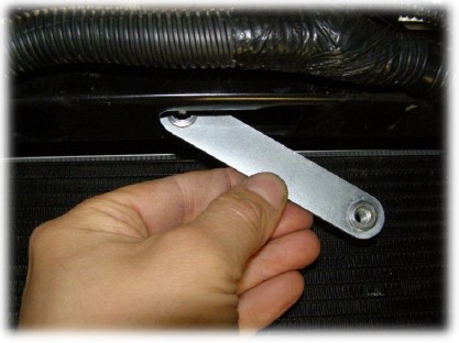
Make sure vehicle is parked on level ground before checking oil level, check the oil level in the supercharger assembly, using the dipstick provided, Tighten the dipstick fully before checking the oil level.
44. Supercharger gear case oil change procedure
Make sure the vehicle is parked on level ground before checking the oil level. Allow sufficient time for the oil level to settle after the engine has been run.
Remove the dipstick from the gear case.
For gear cases without a drain plug follow numerical steps, for gear cases with a drain plug follow the alpha steps.
1. Using a syringe and a 190mm long piece of tube draw out at much oil as possible from the gear case.
A. Place a tray underneath the drain plug to collect the oil once the plug is removed.
B. Remove the drain plug and drain the oil from the case.
C. Re-install and tighten the drain plug to 12Nm.
Fill the gearbox with exactly 60milliters or 2.03 US fluid ounces of fully synthetic SAE 75W-90 gear oil, specifications: API GL5, MT1, such as: Redline 75W90 NS gear oil (factory fill), Castrol Syntrax Universal Plus 75W-90, Lucas synthetic SAE 75W-90 gear oil
Check oil level with the dipstick provided in the supercharger.
Refit the dipstick and tighten to 10Nm.