
How to Install Smittybilt XRC Engine & Transmission Skid Plate on your Wrangler

Shop Parts in this Guide


INSTALLATION:
Step 1: Place the vehicle on a flat, level surface and engage the parking brake.
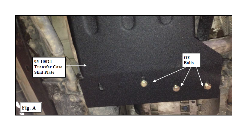
Step 2: Remove the OE crossmember bolts. (Fig. A)
INSTALLATION:
Step 1: Place the vehicle on a flat, level surface and engage the parking brake.
Step 2: Remove the OE crossmember bolts. (Fig. A)
INSTALLATION:
Step 1: Place the vehicle on a flat, level surface and engage the parking brake.
Step 2: Remove the OE crossmember bolts. (Fig. A)
INSTALLATION:
Step 1: Place the vehicle on a flat, level surface and engage the parking brake.
Step 2: Remove the OE crossmember bolts. (Fig. A)


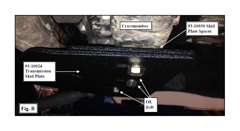
Step 3: Install the transmission skid plate (93-10024) to the crossmember using the previously removed OE bolts. Do not tighten at this time. Leave the OE bolts loose at this time to aid in alignment. If additional space is needed between the skid plate and exhaust install transmission skid plate spacer (93-10030). (Fig. B)
NOTE: If using transmission skid plate (93-10024) in conjunction with the transfer case skid plate (93-10037), mount the transfer case skid plate under the transmission skid plate to ensure a smooth transition.


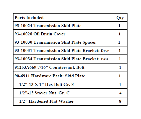
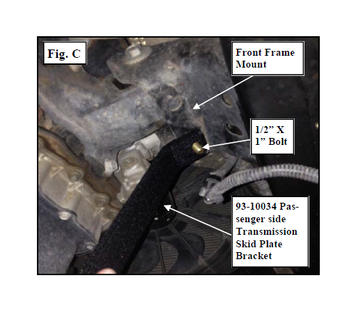
Step 4: Install the passenger side transmission skid plate bracket (93-10034) to the front frame mount hole using the supplied 1/2” X 1” bolt and hardware. Leave the 1/2” bolt loose at this time. (Fig. C)
Step 4: Install the passenger side transmission skid plate bracket (93-10034) to the front frame mount hole using the supplied 1/2” X 1” bolt and hardware. Leave the 1/2” bolt loose at this time. (Fig. C)
Step 4: Install the passenger side transmission skid plate bracket (93-10034) to the front frame mount hole using the supplied 1/2” X 1” bolt and hardware. Leave the 1/2” bolt loose at this time. (Fig. C)
Step 4: Install the passenger side transmission skid plate bracket (93-10034) to the front frame mount hole using the supplied 1/2” X 1” bolt and hardware. Leave the 1/2” bolt loose at this time. (Fig. C)


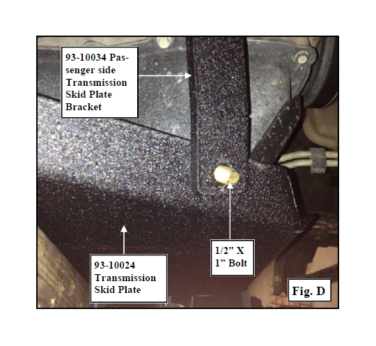
Step 5: Secure the passenger side transmission skid plate bracket (93-10034) to the front of the transmission skid plate (93-10024) using the supplied 1/2” X 1” bolt and hardware. Leave the 1/2” bolt loose at this time. (Fig. D)
Step 5: Secure the passenger side transmission skid plate bracket (93-10034) to the front of the transmission skid plate (93-10024) using the supplied 1/2” X 1” bolt and hardware. Leave the 1/2” bolt loose at this time. (Fig. D)
Step 5: Secure the passenger side transmission skid plate bracket (93-10034) to the front of the transmission skid plate (93-10024) using the supplied 1/2” X 1” bolt and hardware. Leave the 1/2” bolt loose at this time. (Fig. D)
Step 5: Secure the passenger side transmission skid plate bracket (93-10034) to the front of the transmission skid plate (93-10024) using the supplied 1/2” X 1” bolt and hardware. Leave the 1/2” bolt loose at this time. (Fig. D)


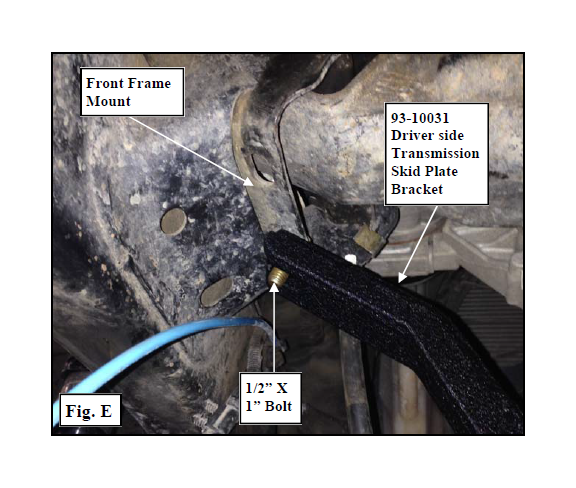
Step 6: Install the driver side transmission skid plate bracket (93-10031) to the front frame mount hole using the supplied 1/2” X 1” bolt and hardware. Leave the 1/2” bolt loose at this time. (Fig. E)
Step 6: Install the driver side transmission skid plate bracket (93-10031) to the front frame mount hole using the supplied 1/2” X 1” bolt and hardware. Leave the 1/2” bolt loose at this time. (Fig. E)
Step 6: Install the driver side transmission skid plate bracket (93-10031) to the front frame mount hole using the supplied 1/2” X 1” bolt and hardware. Leave the 1/2” bolt loose at this time. (Fig. E)
Step 6: Install the driver side transmission skid plate bracket (93-10031) to the front frame mount hole using the supplied 1/2” X 1” bolt and hardware. Leave the 1/2” bolt loose at this time. (Fig. E)


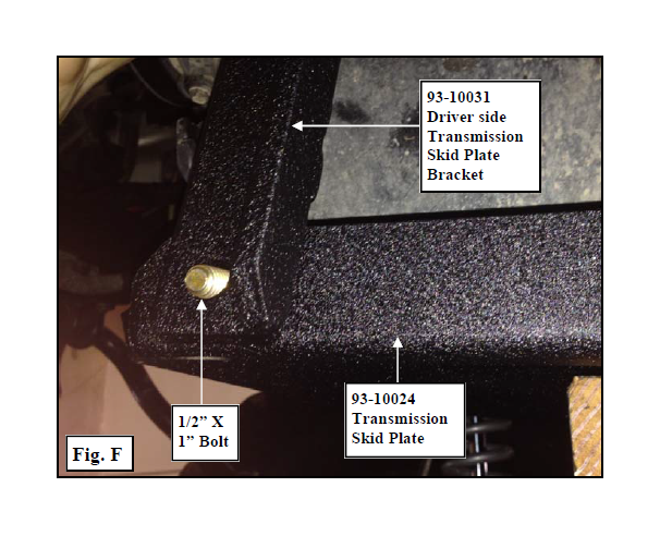
Step 7: Secure the driver side transmission skid plate bracket (93-10031) to the front of the transmission skid plate (93-10024) using the supplied 1/2” X 1” bolt and hardware. Leave the 1/2” bolt loose at this time. (Fig. F)
Step 7: Secure the driver side transmission skid plate bracket (93-10031) to the front of the transmission skid plate (93-10024) using the supplied 1/2” X 1” bolt and hardware. Leave the 1/2” bolt loose at this time. (Fig. F)
Step 7: Secure the driver side transmission skid plate bracket (93-10031) to the front of the transmission skid plate (93-10024) using the supplied 1/2” X 1” bolt and hardware. Leave the 1/2” bolt loose at this time. (Fig. F)
Step 7: Secure the driver side transmission skid plate bracket (93-10031) to the front of the transmission skid plate (93-10024) using the supplied 1/2” X 1” bolt and hardware. Leave the 1/2” bolt loose at this time. (Fig. F)


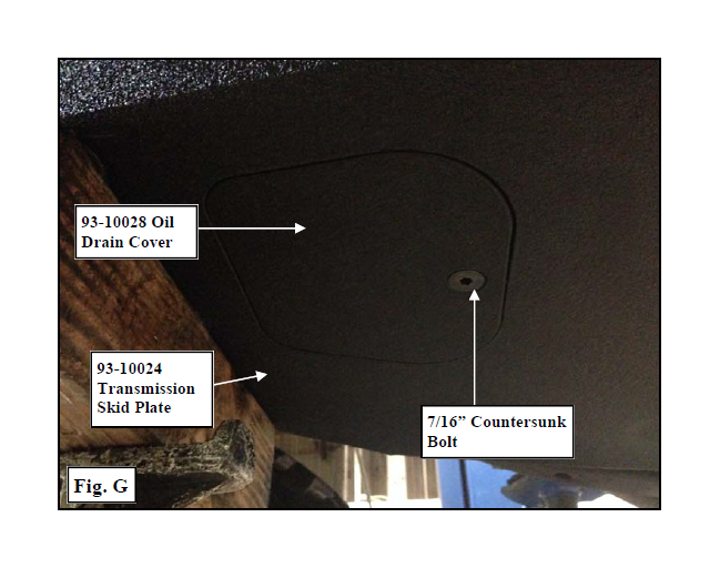
Step 8: Install the oil drain cover (93-10028) to the transmission skid plate (93-10024) using the supplied 7/16” countersunk bolt. (Fig. G)
Step 8: Install the oil drain cover (93-10028) to the transmission skid plate (93-10024) using the supplied 7/16” countersunk bolt. (Fig. G)
Step 8: Install the oil drain cover (93-10028) to the transmission skid plate (93-10024) using the supplied 7/16” countersunk bolt. (Fig. G)
Step 8: Install the oil drain cover (93-10028) to the transmission skid plate (93-10024) using the supplied 7/16” countersunk bolt. (Fig. G)


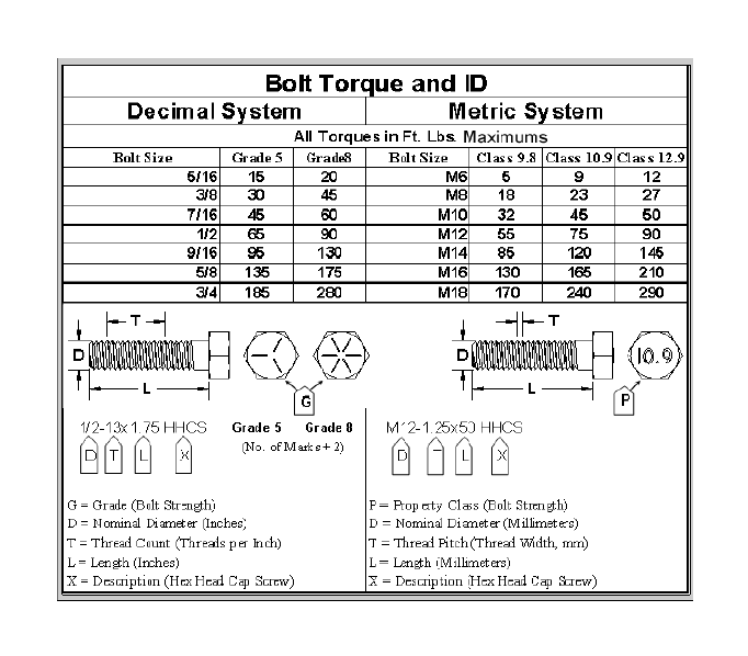
Step 9: Torque the OE evap canister skid plate hardware to manufacturer’s specifications, the 1/2” hardware to ?? ft./lbs. and the 7/16” hardware to 50 ft./lbs.
Step 10: Installation is now complete.
Step 9: Torque the OE evap canister skid plate hardware to manufacturer’s specifications, the 1/2” hardware to ?? ft./lbs. and the 7/16” hardware to 50 ft./lbs.
Step 10: Installation is now complete.
Step 9: Torque the OE evap canister skid plate hardware to manufacturer’s specifications, the 1/2” hardware to ?? ft./lbs. and the 7/16” hardware to 50 ft./lbs.
Step 10: Installation is now complete.
Step 9: Torque the OE evap canister skid plate hardware to manufacturer’s specifications, the 1/2” hardware to ?? ft./lbs. and the 7/16” hardware to 50 ft./lbs.
Step 10: Installation is now complete.
