FREE 1 to 3-Day Delivery on Orders $149+ Details

How to Install SkyJacker Rear Air Bump Stop Kit (07-18 Wrangler JK) on your Jeep Wrangler
Tools Required
- Safety Glasses
- Metric / Standard Sockets & Wrenches
- 3/16" Hex Key
- C-Clamp
- Cut Off Wheel / Grinder
- Drill / 1/8" Drill Bit
- Plasma Cutter
- Pneumatic Body Saw
- Welding Machine
- Floor Jack
- Jack Stands
- Torque Wrench

Shop Parts in this Guide
Before beginning the installation, read these instructions & the enclosed driver’s WARNING NOTICE thoroughly & completely. Also affix the WARNING decal in the passenger compartment in clear view of all occupants. Please refer to the Parts List to insure that all parts & hardware are received prior to the disassembly of the vehicle. If any parts are found to be missing, contact SKYJACKER® Customer Service at 318-388-0816 to obtain the needed items. If you have any questions or reservations about installing this product, contact SKYJACKER® Technical Assistance at 318-388- 0816.
Important Note: The installation of this Skyjacker rear air bump stop kit requires cutting of the OEM frame. An experienced fabricator / welder is recommended to properly install this product.
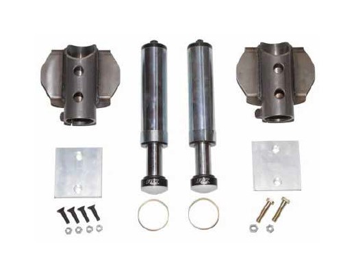
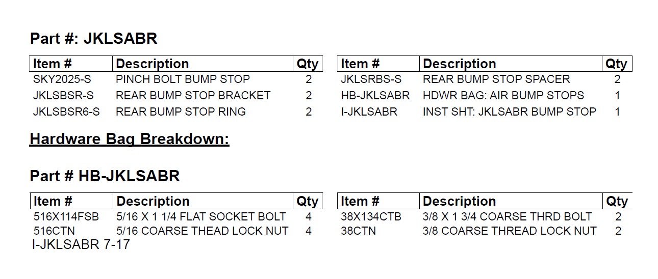
Component Box Breakdown:
Installation:
1. With the vehicle on flat level ground, set the emergency brake, & block the front tires / wheels.
2. Raise the rear of the vehicle using a floor jack & support the frame rails using jack stands.
3. Support the rear differential using a floor jack & remove the rear tires / wheels.
4. Disconnect the rear sway bar end links from the rear differential.
5. Disconnect the rear track bar from the rear differential.
6. Disconnect the rear shocks from the rear differential.
7. Disconnect the rear brake line brackets from the frame.
8. While checking for adequate slack in the ABS lines, brake lines, differential breather hose, & etc. Lower the rear differential & remove the coil springs & rubber isolators.
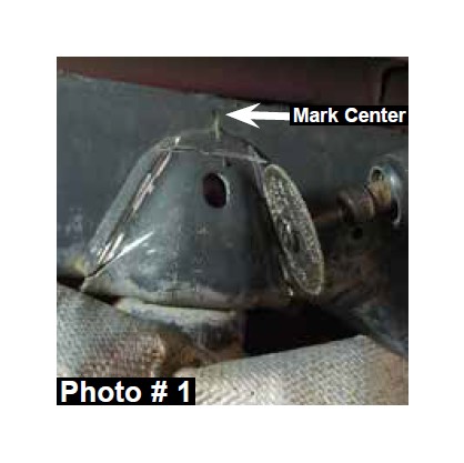
10. Mark the upper frame at the center of the OEM bump stop bracket welded to the frame. (See Arrow in Photo #1)
11. Remove the OEM bump stop bracket from the frame by cutting along the welds using a cut off wheel or similar tool. (See Photo # 1) Note: Be careful of throwing sparks near the fuel tank, fuel lines, or flammable materials & not to cut into the frame.
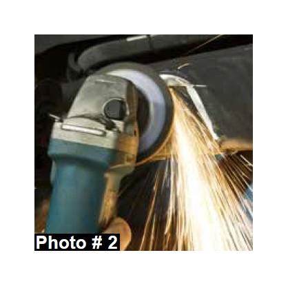
12. Clean up the remaining welds & any imperfections on the frame using a grinder or similar tool. (See Photo # 2) Note: Be careful of throwing sparks near the fuel tank, fuel lines, or flammable materials.
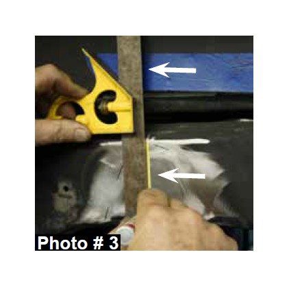
13. Locate the previously made mark on the frame from Step # 10 & draw a straight line along the frame & rear fender well using a square or similar tool. (See Photo # 3)
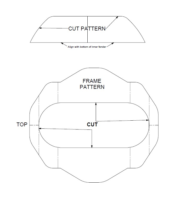
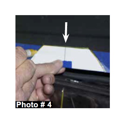
14. Align the centerline of the supplied rear fender well cut pattern located on Page # 7 with the previously made line on the rear fender well from Step # 13 & draw a line along the outside of the rear fender well cut pattern. (See Photo # 4)
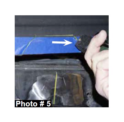
15. Cut along the previously drawn line on the rear fender well from Step # 14 using a pneumatic body saw or similar tool. (See Photo # 5)
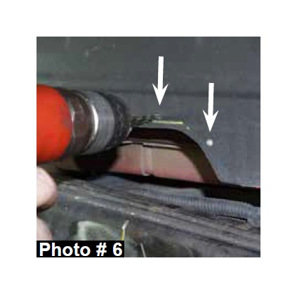
16. Drill a few holes around the previously cut area of the rear fender well from Step # 15 using a drill & 1/8" drill bit. (See Photo # 6)
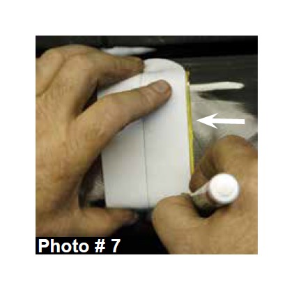
17. Align the centerline of the supplied frame cut pattern located on Page # 7 with the previously made line on the frame from Step # 13 & draw a line along the outside of the frame cut pattern. (See Photo # 7)
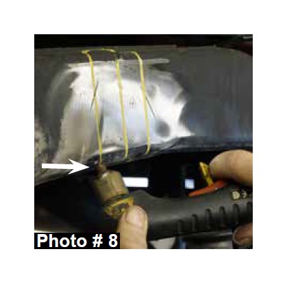
18. Cut along the previously drawn line on the frame from Step # 17 using a plasma cutter or similar tool. (See Photo # 8)
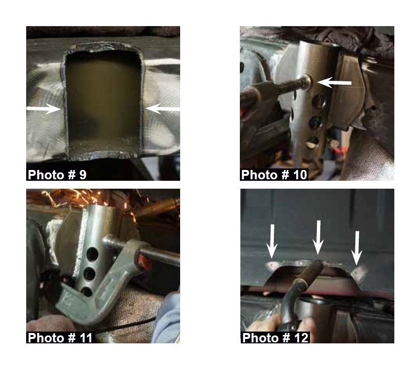
19. Clean up any imperfections on the frame using a grinder or similar tool. (See Photo # 9) Note: Be careful of throwing sparks near the fuel tank, fuel lines, or flammable materials.
20. Install the new Skyjacker bump stop bracket into the new frame cut out using a C-clamp. (See Photo # 10)
21. Weld the new Skyjacker bump stop bracket to the frame using a welding machine. (See Photo # 11) Note: Be careful of throwing sparks near the fuel tank, fuel lines, or flammable materials.
22. Plug weld the previously drilled 1/8" holes of the rear fender well from Step # 16 using a welding machine. (See Photo # 12) Note: Be careful of throwing sparks near the fuel tank, fuel lines, or flammable materials.
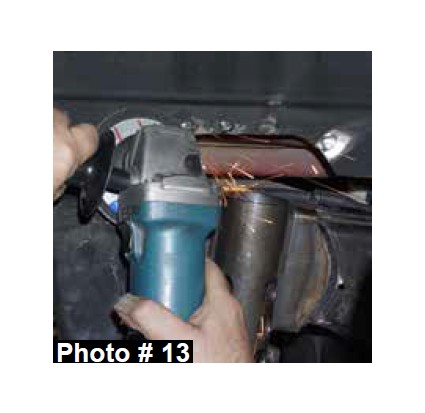
23. Clean up any imperfections on the rear fender well using a grinder or similar tool. (See Photo # 13) Note: Be careful of throwing sparks near the fuel tank, fuel lines, or flammable materials.
24. Prime / paint all raw metal exposed from the installation of the new Skyjacker bump stop bracket.
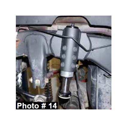
25. 4" Lift: Install the new Skyjacker air bump stop into the new Skyjacker bump stop bracket & secure using the supplied 3/8” x 1 3/4” coarse thread bolts, nuts, & a 9/16” socket / wrench. (See Photo # 14) Note: Torque each 3/8” pinch bolt to 20 ft. lbs. Do not over tighten or damage will occur to the new Skyjacker air bump stop.
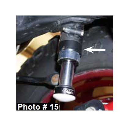
26. 6" Lift: Install the new Skyjacker air bump stop ring onto the new Skyjacker air bump stop & install into the new Skyjacker bump stop bracket. Secure using the supplied 3/8” x 1 3/4” coarse thread bolts, nuts, & a 9/16” socket / wrench. (See Photo # 15) Note: Torque each 3/8” pinch bolt to 20 ft. lbs. Do not over tighten or damage will occur to the new Skyjacker air bump stop.
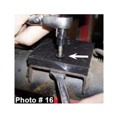
27. Install the new Skyjacker rear bump stop spacers to the OEM rear bump stop pad using the supplied 5/16" x 1 1/4" flat socket head bolts, nuts, a 3/16" hex key socket / wrench, & a 1/2" wrench. (See Photo # 16)
28. Install the coil springs & rubber isolators.
29. Connect the rear brake line brackets to the frame using the OEM hardware.
30. Connect the rear shocks to the rear differential using using the OEM hardware.
31. Connect the rear track bar to the rear differential using using the OEM hardware.
32. Connect the rear sway bar end links to the rear differential using the OEM hardware.
33. Install the rear tires / wheels & lower the vehicle to the ground.
Final Notes:
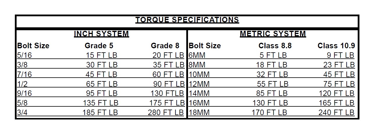
• After the installation is complete, double check that all nuts & bolts are tight. Refer to the following chart for the proper torque specifications. (Do not retighten the nuts & bolts where thread lock compound was used.)
• With the vehicle placed on the ground, cycle the steering lock to lock & inspect the steering, suspension, brake lines, front & rear drivelines, fuel lines, & wiring harnesses for proper operation, tightness, & adequate clearance.
• After the first 100 miles, check all hardware for the proper torque & periodically thereafter.
• The above specifications are not to be used when the bolt is being installed with a bushing.