FREE 1 to 3-Day Delivery on Orders $149+ Details

How to Install S & B Cold Air Intake w/ Oiled Cleanable Cotton Filter (07-11 3.8L Wrangler JK) on your Jeep Wrangler
Installation Time
30 minutes
Tools Required
- 10mm Wrench or Socket
- Phillips Head Screwdriver
- 5/16” Nut Driver or Flat Blade Screwdriver

Shop Parts in this Guide
BEFORE YOU START
• Please read the entire product guide before proceeding.
• Ensure all components listed on page 4 are present.
• If you are missing any of the components, call our customer support at (909) 947-0015.
• Do not work on your vehicle while engine is hot.
• Make sure the engine is turned off and the vehicle is in Park or the Parking Brake is set.
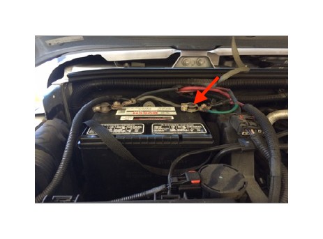
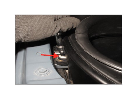
1. With the ignition switched off and the parking brake set, disconnect the negative battery cable. Note: Failure to disconnect the battery may cause the CEL to illuminate upon completion of the installation and subsequent operation. Do not skip this step!
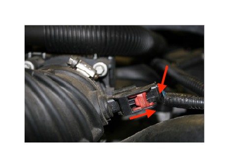
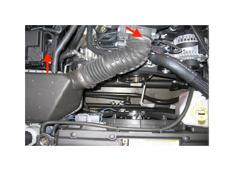
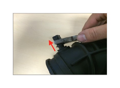
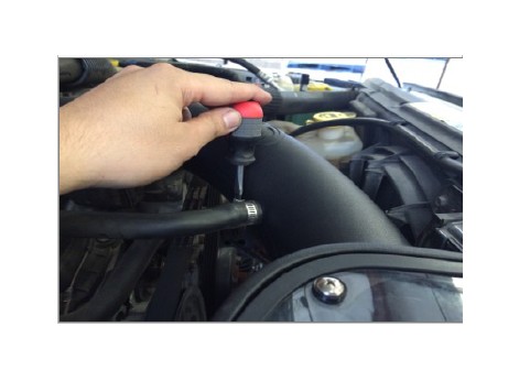
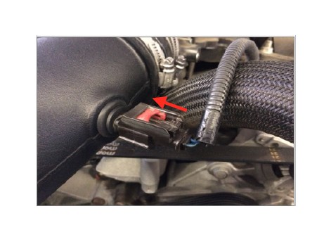
2. Pull the red tab back to unlock and press on the clip to disconnect the wire harness from the IAT sensor.
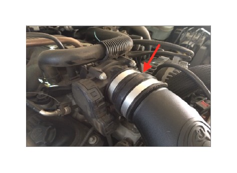
3. Loosen the hose clamp at the throttle body and disconnect the crankcase vent line at the stock air box.
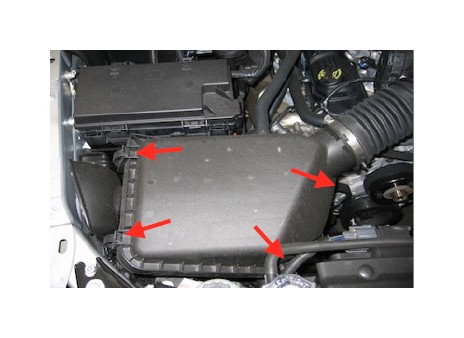
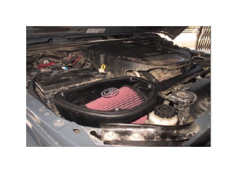
4. Unclip the latches on the stock air box lid and remove both the lid and tube assembly from the vehicle.
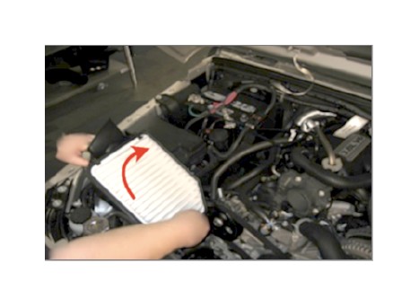
5. Pull the stock air box straight up to remove from the vehicle.
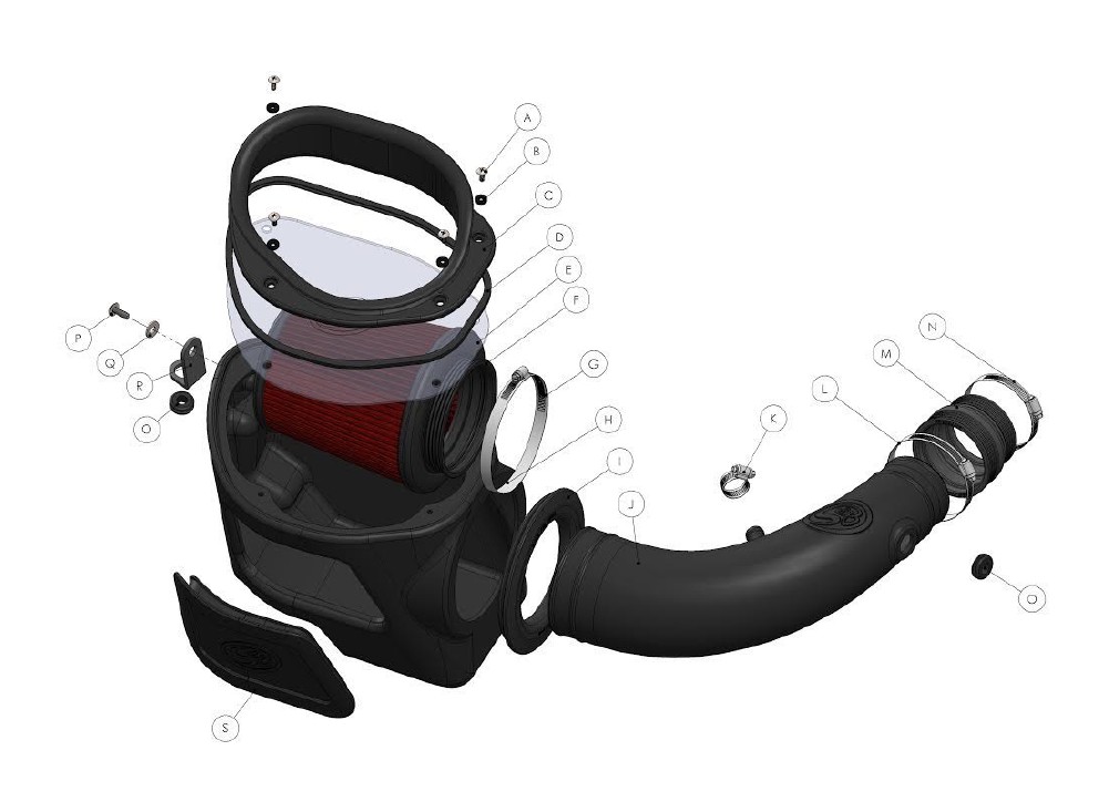
6. Push the Hood Box Seal (I) into the Air Box (H).
7. Feed the Air Tube (J) through the Hood Box Seal (I) into the Air Box (H).
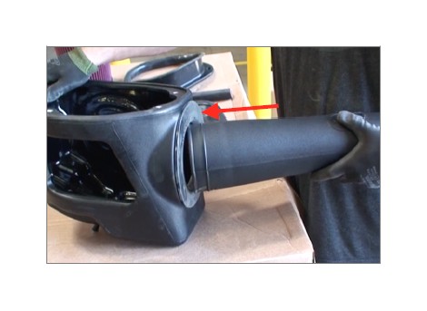
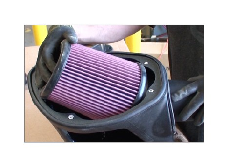
8. Place the Air Filter (F) into the Air Box (H) and slide it onto the Air Tube (J). Tighten down the #80 Hose Clamp (G).
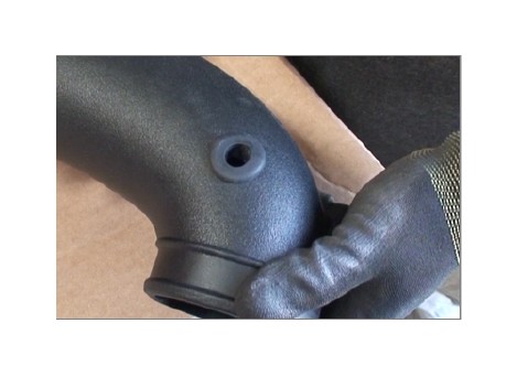
9. Insert the Grommet (O) into the hole on the Air Tube (J).
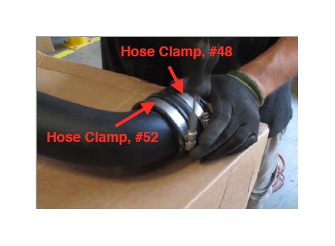
10. Install the Step Coupler (M) and two Hose Clamp #52 & #48 (L & N) onto the Air Tube throttle body side. Tighten hose clamp #52 and leave hose clamp #48 loose.
11. Apply Loctite Thread Locker (T) on the threads of the Screw (P).
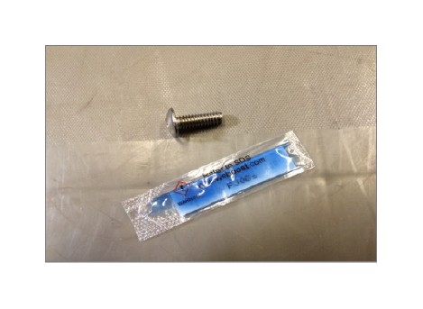
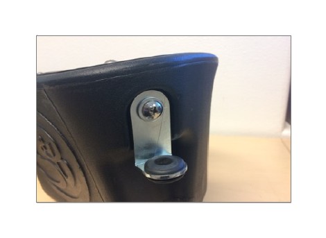
12. Install the Bracket (R) into the side of the Air Box (H) with the supplied Screw (P) and Washer (Q). Insert the Grommet (O) in the hole on the bottom end of the bracket.
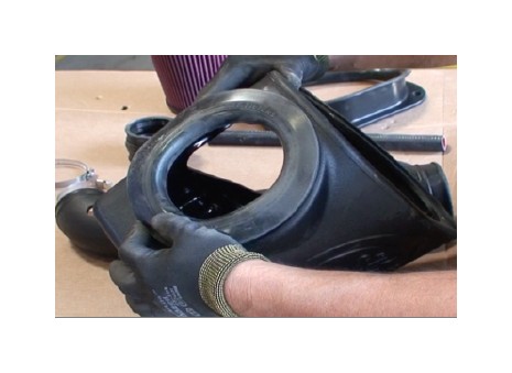
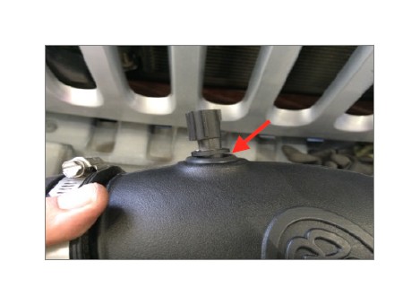
13. Remove the IAT sensor from the stock air tube. If necessary use pliers to help remove the sensor.
14. Insert the IAT sensor into the Air Tube (J). Make sure that the base of the sensor is seated up to the Grommet (O).
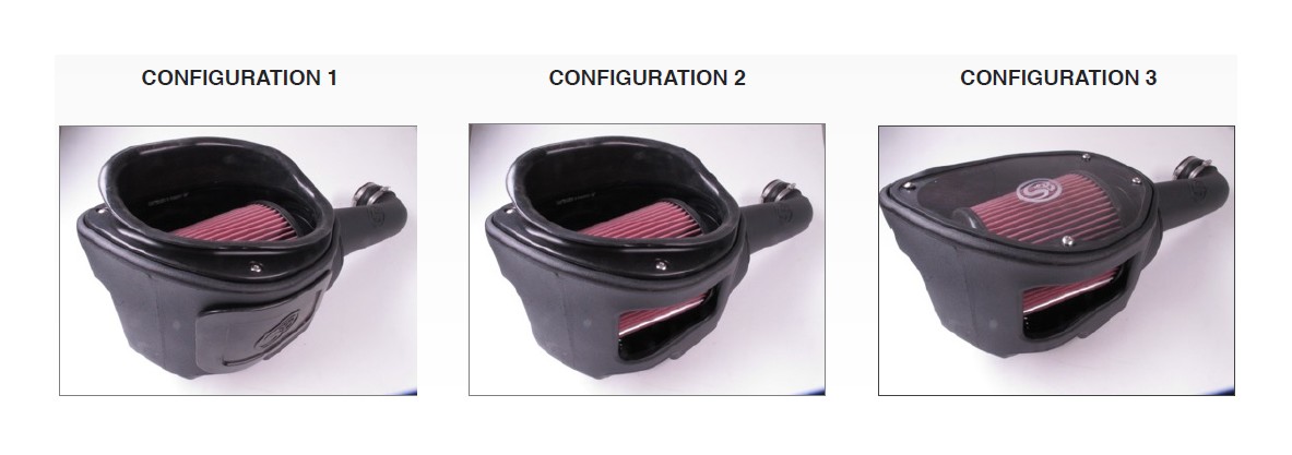
15. Choose Your Air Flow. Go to Page 3 to see pictures of the configurations.
• Configuration 1: Hood Box Seal (C) and Fender Box Seal (S) Installed
• Configuration 2: Hood Box Seal (C) Installed and Silicone Box Seal (S) Not Installed
• Configuration 3: Clear Lid (E) Installed and Fender Box Seal (S) Not Installed -
Note: Configuration 3 is the default setup for this installation instructions.
WARNING!! Do not install the Clear Lid with the Silicone Air Box plug. Doing this will cause your filter to collapse and will void your warranty.
16. Locate the bolt on the side of the plastic tray and remove it.
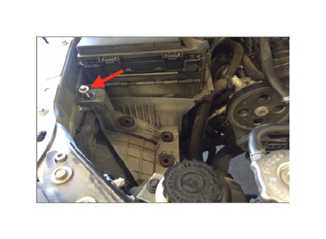
17. Install the Air Box (H), push down on the box until the box tabs are completely seated on the factory grommets. Use the bolt that was just removed to tighten down the air box. Note: If Configuration 1 was chosen, insert the Fender Box Seal (S) before installing the Air Box (H).
18. Install the Step Coupler (M) onto the throttle body and tighten down the #48 Hose Clamp (N).
19. Insert the stock crankcase vent line into the side of the Air Tube (J) and tighten Hose Clamp, #12 (K).
20. Reconnect the wire harness into the IAT sensor. Push the red tab forward to lock the wire harness in place.
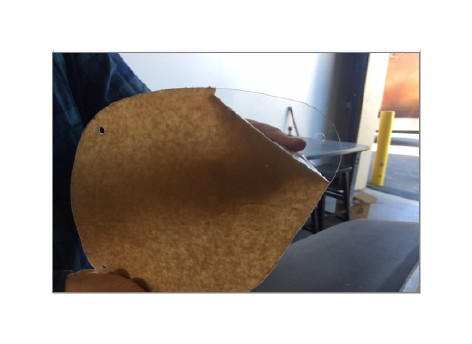
21. Remove the protective covering from the Clear Lid (E).
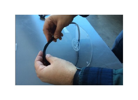
22. Install the Edge Trim (D) on the Clear Lid (E).
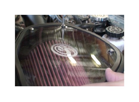
23. Place the lid on top of the Air Box (H) and secure the Clear Lid (E) using the four provided Screw (A) and Washer (B). Note: If Configuration 1 or 2 was chosen, install your Hood Box Seal (C) using the provided Screw (A) and Washer (B)
24. Reconnect the negative terminal on the battery. Inspect your installation, make sure the kit is properly positioned and all fasteners are secure. The installation is now complete.
CHOOSE YOUR AIR FLOW
KIT SPECIFIC FEATURES:
*The 75-5080 kit has three airflow configurations that you can choose from depending on your airflow requirements.
• Configuration 1: Silicone Hood Seal and Silicone Air Box Plug installed
• Configuration 2: Silicone Hood Seal installed and Silicone Air Box Plug not installed
• Configuration 3: Clear Lid installed and Silicone Air Box plug not installed
The airflow restriction for all three configurations are very similar. Choosing one over another would have minimal effect on performance.
WARNING!! Do not install the Clear Lid with the Silicone Air Box plug. Doing this will cause your filter to collapse and will void your warranty.
PERFORMANCE TESTING
• Engage parking brake and start your engine. Listen for abnormal noises. If an air leak is detected, re-inspect hoses and connections as they may need to be repositioned and tightened.
• S&B FILTERS recommends that you keep your OE intake system in the event it is required in the future.
• In order to maintain your warranty, all connections and components must be checked periodically for alignment and for proper tension on all connections. Failure to do so may void your warranty.
• Use only S&B FILTERS cleaning and oil products to service your filter. Using any other brand oil and or cleaners on your S&B air filter may void your warranty.
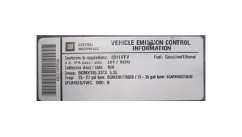
WARNING! If your vehicle has a Vehicle Emission Control Information decal affixed to the factory air box, a new replacement label must be obtained and installed in a readily visible position in the engine compartment in order to remain CARB compliant. Failure to do so will prevent the vehicle from passing a smog check. Replacement labels can be ordered from your local dealership. Regulations state that the VECI label shall not be affixed to any equipment which is easily detached from the vehicle. Label placement, under the hood on a painted surface is recommended.
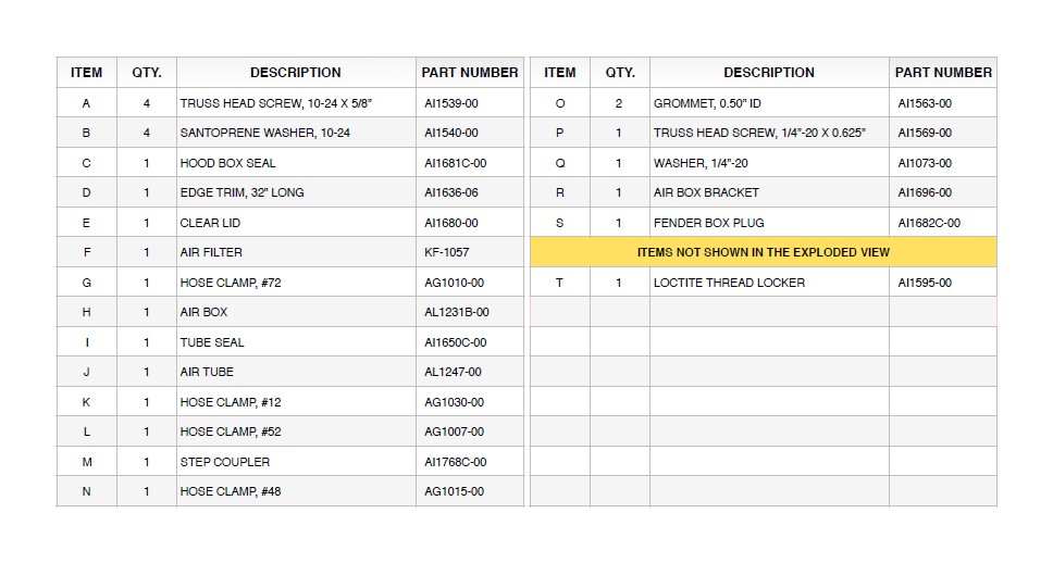
EXPLODED VIEW