FREE 1 to 3-Day Delivery on Orders $149+ Details

How to Install a Rugged Ridge XHD Gen II Swing & Lock Tire Carrier on your Jeep Wrangler
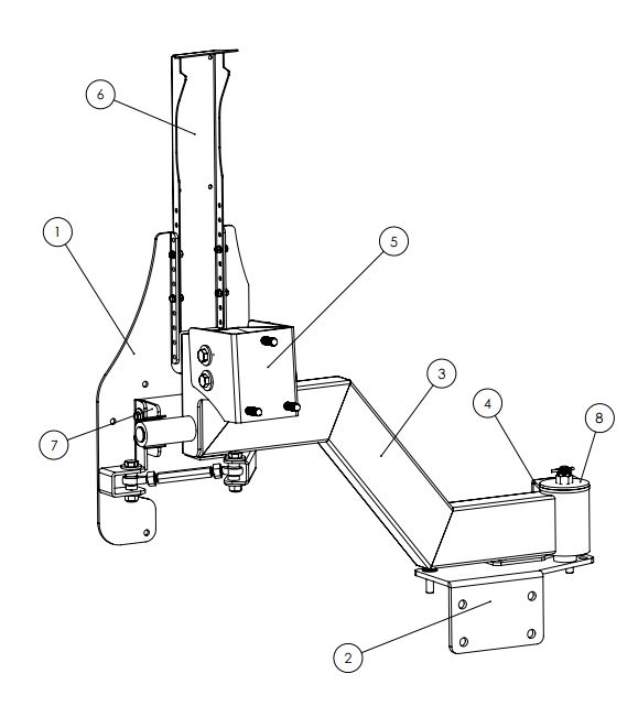
Components:
1. Tailgate Bracket
2. Spindle Bracket
3. Main Arm
4. Spindle Brace
5. Tire Bracket
6. Brake Light Extension
7. Saddle
8. Spindle Cap
Hardware Included:
2 x Long M12 Bolts
4 x Short M12 Bolts
6 x Medium M12 Bolts
2 x M8 Bolts
4 x M6 Bolts
18 x M12 Flat Washers
4 x M8 Flat Washers
8 x M6 Flat Washers
6 x M12 Nylon Lock Nuts
2 x M8 Nylon Lock Nuts
4 x M6 Nylon Lock Nuts
3 x 1/2”-20 Lug nuts
2 x Long Light Screw
2 x Short Light Screw
2 x Tapered Bearing
1 x Bottom Spindle Cap
1 x LH Rod End
1 x RH Rod End
1 x LH M12 Jam Nut
1 x RH M12 Jam Nut
1 x Rod End Connector
1 x Cotter Pin
1 x M16 Castle Nut
4 x Heim Joint Spacers
Works with: XHD Rear Bumper 11546.20 & XHD Aluminum Bumper Pods 11547.01
Installation Instructions
CAUTION: To reduce risk of personal injury during assembly and use of this product:
• Wear gloves and safety glasses during installation.
• Tire Carrier and spare tire/wheel are heavy. Use jack or seek assistance when lifting, fastening parts, or installing wheel/tire to carrier.
• Tire Carrier is subject to vibration and shock loads from on and off road use. Regularly inspect carrier and lug nuts fastening spare to carrier. Do not use and repair if damaged. Use thread locker and keep lug nuts torqued to 80 ft./lbs.
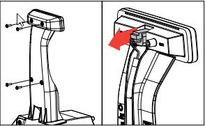
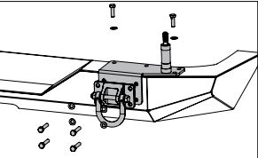
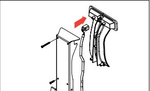
1. Remove 4 torx head screws that attach light to factory tire mount. Pull light away from tire mount.
2. Remove connector by pushing down on tab and pulling. Set light aside, it will be used later during installation. Place connector and wires off to side to not interfere with Tire Carrier installation.
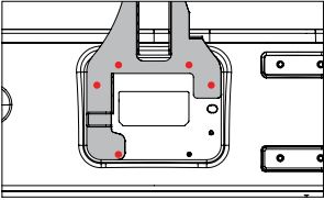
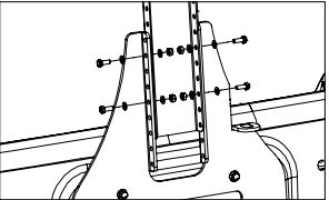
3. Remove existing tire carrier. Attach Tailgate Bracket to tailgate using factory hardware in locations shown in red.
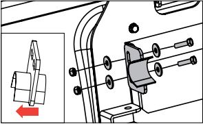
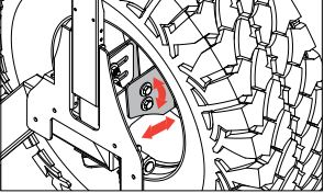
4. Remove right D-Ring from bumper. Install Spindle Bracket by inserting four hex bolts and washers supplied with rear bumper through Spindle Bracket and D-Ring. Thread two medium M12 bolts with washers into top of Spindle Bracket.
Note: D-Ring holes are slightly wider on top than bottom.
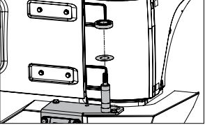
5. Install Bottom Spindle Cap onto spindle. Install bearing onto spindle. Ensure widest portion of bearing is on bottom.
Note: Pack bearings with marine grade grease prior to installation.
6. Install Saddle onto Tailgate Bracket using supplied M8 bolts, washers and nylon lock nuts.
NOTICE: Longer part of saddle should face left of vehicle. Carrier must fully engage saddle. Additional adjustment may be required after full assembly is complete.
7. Place arm over spindle.
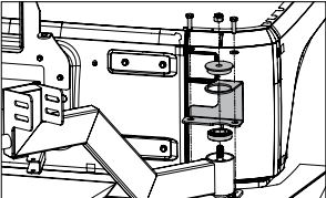
8. Install other bearing onto spindle, ensuring the widest portion of bearing is on top and will align with bearing surface of Arm. Install Spindle Brace over arm, followed by Spindle Cap and Castle nut. Fasten Spindle Brace to Spindle Bracket using supplied medium M12 hex bolts and washers.
NOTICE: Pack bearing in marine grade grease before installation. Make sure bearing/spindle assembly remains greased during routine inspection and maintenance. Ensure concentric alignment of bearing, brace, arm, and cap with spindle.
9. Install Tire Bracket to Arm using supplied short M12 hex bolts, M12 fender washers, and nylon lock nuts.
Note: Final adjustment of Tire Bracket will be done after spare tire is mounted.
10. Install Brake Light Extension using supplied M6 hex bolts, washers, and nylon lock nuts.
CAUTION: Your Jeep® high-mounted brake light is mandatory highway safety equipment. Do not delete and ensure light is visible over your choice of spare wheel/tire. Final position of light may need to be adjusted to ensure proper visibility once spare tire is mounted (see instructions below).
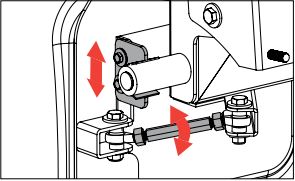
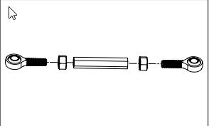
11. Assemble rod ends and jam nuts as shown.
NOTICE: LH and RH components are not interchangeable; ensure each is assembled with corresponding parts.
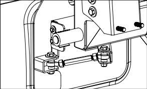
12. Install linkage, connecting main arm to tailgate bracket using supplied long M12 bolts, washers, nylon lock nuts and M12 spacers.
NOTICE: After spare tire is mounted, spacer and rod end orientation may need to be adjusted for additional clearance when mechanism is operated. Ensure adjustment provides for full engagement of carrier end in saddle with spare tire/wheel mounted.
13. Once Tire Carrier installation is complete, before installation of spare tire, reconnect wires to factory third brake light by pushing connector until it clicks.
14. Install factory third brake light to Brake Light Extension using provided screws. Long screws are for top two holes. Short screws are for bottom two holes.
OPTIONAL: For larger spare tires, it may be necessary to raise Brake Light Extension to be seen over spare tire. This will require additional wire to be spliced and added to factory third brake light wires.
15. Open tailgate and remove plastic vent by pulling on left side until clips release.
16. Unplug connector by pushing in tab and pulling down.
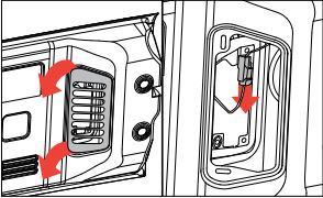
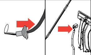
17. Remove rubber grommet in tailgate and pull wire and connector through hole.
18. In section of wire between upper-most connector and mesh cover, cut and splice in additional wire length.
19. Reinstall rubber grommet in tailgate. Reconnect wire connector inside tailgate. Reinstall plastic tailgate vent.
20. Final Adjustment: Tire bracket should be rotated and translated so as to move tire as close to main arm as possible.
21. Final Adjustment: Rod end connector should be rotated until main arm is secured in saddle and jam nuts should be tightened against connector to eliminate possible loosening
22. Final Adjustment: Saddle height should be adjusted to engage main arm’s bushing