 FREE 1 to 3-Day Delivery on Orders $149+ Details

How to Install Rugged Ridge Wall Mount Freedom Panel Holder (07-18 Jeep Wrangler JK) on your Jeep Wrangler
Installation Time
45 minutes
Tools Required
- Pencil
- Stud Finder
- Tape Measure
- Level (A level with a built-in magnet is very helpful.)
- Ratchet with 1/2” Socket
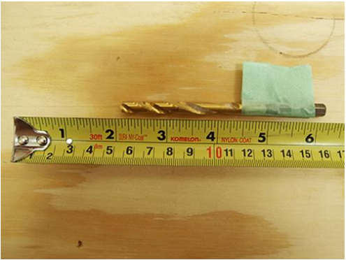
- Drill with 1/4” Drill Bit

Shop Parts in this Guide
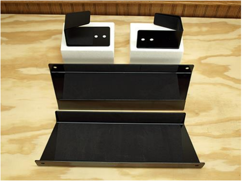
There is a total of 4 parts. 2 – Lower Brackets and 2 – Retainer Brackets
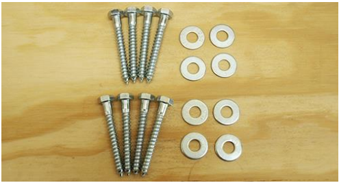
Note: You will need to purchase eight (8) 5/16” lag bolts at least 2-1/2” long and eight (8) 5/16” flat washers from your local hardware store. Lag bolts and washers are NOT supplied with the brackets. The lag bolts that were used for this install had a 1/2” head and were 2-1/2” long. Also, the holes in the Lower Brackets are made for 16” on center studs. You will need to determine additional materials to appropriately secure the brackets if your wall has 24” on center studs.
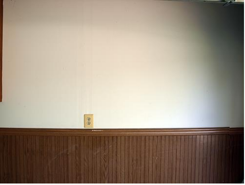
Before Install
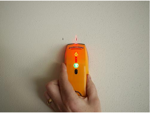
1. Locate and mark a total of 4 studs using a stud finder.
2. Begin by installing the left Lower Bracket of the Freedom Mount. Determine the height you wish to place the Lower Brackets before drilling pilot holes. The placement of the Lower Brackets will be based on one’s personal preference of the location where the Freedom Panels will be stored. Note: Bolt holes need to be drilled at least 2” into the stud past the drywall. Optional: Place tape 2-1/2” from the tip of the drill bit if using 2-1/2” lag bolts. This will help with consistency for the depth of all pilot holes.
3. Place the left Lower Bracket on the wall once you’ve determined the desired height. Mark the first pilot hole to be drilled in the wall with a pencil. Drill the pilot hole. Place a washer on a lag bolt. Insert the lag bolt through the Lower Bracket and into the wall tightening it with a ratchet with 1/2” socket.
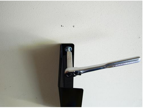
Note: Don’t tighten the lag bolt all the way. The Lower Bracket will need to be leveled for the pilot hole to be drilled on the opposite end.
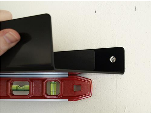
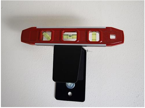
4. Place a level on the Lower Bracket to help determine the location of the second pilot hole. With the second pilot hole drilled, place a washer on a lag bolt. Insert the lag bolt through the Lower Bracket hole and into the wall. Tighten both lag bolts securing the bracket to the wall.
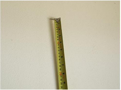
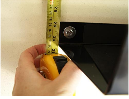
5. With the tape measure on the right side of the Lower Bracket, measure 29-1/2” from the bracket bottom towards the ceiling. Place a pencil mark at the end of the tape measure at the top. This is where the top of the Retainer Bracket will be placed.
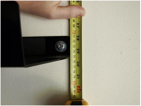
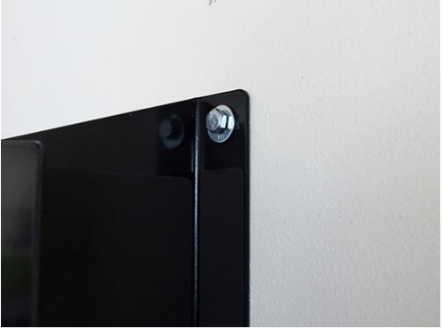
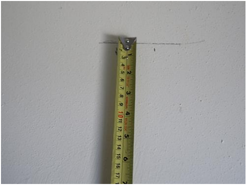
6. Locate the stud using the stud finder. Align the top of the Retainer Bracket with the pencil mark. Mark the location for the top pilot hole. Drill the hole. Place a washer on a lag bolt. Insert the lag bolt through the Retainer Bracket hole and into the wall. Do Not tighten the lag bolt as you will need to level the Retainer Bracket.
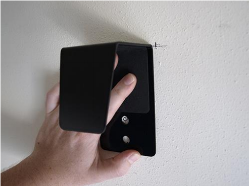
7. With the Retainer Bracket level, drill a pilot hole into the wall through the bottom hole of the Retainer Bracket. Place a washer on a lag bolt. Insert the lag bolt through the Retainer Bracket and into the wall. Tighten both lag bolts securing the bracket to the wall.
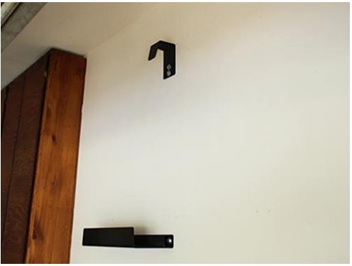
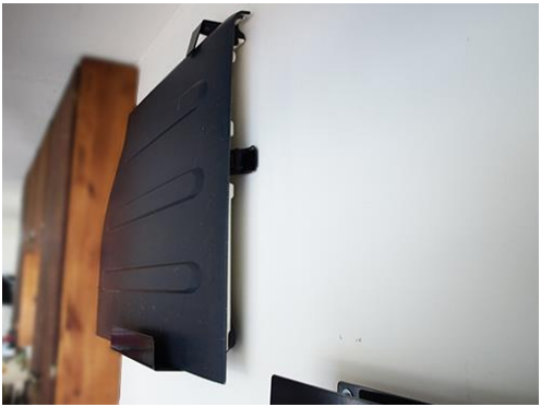
This is what the left side Lower Bracket and Retainer Bracket should look like.
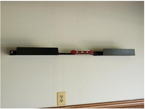
8. Repeat steps 3 – 4 for the right Lower Bracket. Hint: Take a straight 2x4 or long ruler, as shown in picture below, if you wish to maintain the same height as the left Lower Bracket.
9. Place the tape measure on the left side of the right Lower Bracket. Measure 30-1/2” from the bracket bottom to the ceiling. Place a pencil mark at the end of the tape measure at the top. This is where the top of the right-side Retainer Bracket will be placed.
10. Repeat steps 6 – 7 for securing the right-side Retainer Bracket to the wall. Remember that this bracket will be 30-1/2” from the Lower Bracket.

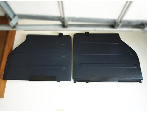
11. Slide the shorter Freedom Panel into the Lower Bracket on the left side and the taller one into the Lower Bracket on the right side.
After Install
Installation Instructions Written by ExtremeTerrain Customer Brian Voelzke 07/01/2018

