FREE 1 to 3-Day Delivery on Orders $149+ Details

How to Install a Rugged Ridge Low Mount XHD Snorkel on your 2012-2014 Wrangler JK 3.6L
Installation Time
1 hours
Tools Required
- (1) Drill / with 1/8”, 5/16” and 7/32” drill bits
- (2) Angle grinder or Dremmel tool / with metal cutoff wheel
- (3) High quality sealant (RTV)
- (4) (T-40) & (T-30) Torx bit screw driver or socket
- (5) Quality black satin spray paint & painters masking tape
- (6) 1” - 2” Putty knife
- (7) Body color touch up paint
- (8) Super glue
- (9) Allen wrench set
- (10) Sand paper or sanding block

Shop Parts in this Guide
Contents:
(1) Main modular snorkel body
(1) Rugged Ridge logo plate
(1) Aluminum air tube
(1) Lower air filter housing
(2) M8 x 35mm hex head bolt
(4) M8 flat washer
(2) M8 nut
(1) 3” Silicone 90deg elbow
(1) 3” Silicone 45deg elbow
(4) 3“ Hose clamp
(1) 3/8” Clear drain hose (12”)
(1) 3/8” Drain valve
(3) 3/8” Hose clamp
(4) Air box sealing clamp
(4) M6 x 20mm caps head bolt
(2) M6 x 55mm caps head bolt
(6) M6 flat washer
(1) Fender & intake “U” gasket (24”)
(1) Low mount air intake
(1) Cowl re-mount bracket
(4) M6 x 20mm flange hex bolt
(4) M6 flange nut
(2) Plastic spacer
(1) Cowl mount “Z” bracket
(1) Cowl mount nut plate (M5)
(4) M5 x 25mm Phillips head bolt
(4) M5 Nylon cowl washer
XHD snorkel system has been designed for 2007-2013 Jeep Wangler 4dr and 2dr LHD models equipped with 3.8L & 3.6L (V6). Diesel and RHD drive vehicles will not be able to use the following kits: (17756.06 17756.08, 17756.20, 17756.21).
NOTICE: Modular XHD Snorkel will require drilling, cutting and modification of vehicle. Before proceeding please read installation instructions for complete understanding of skills required for installation. To assure optimum performance and durability of your XHD snorkel system a professional installer may be required.
XHD snorkel has been designed for use with either a stock or lifted suspension systems. Snorkel should not be used with body lifts over 1”. Body lifts taller than 1” will cause misalignment of intake components possible resulting in failure of sealed system. Final inspection by installer should be performed to insure all intake connections are properly sealed and tightened before operation of vehicle.
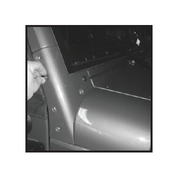
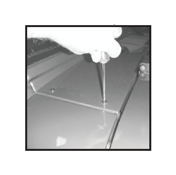
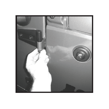
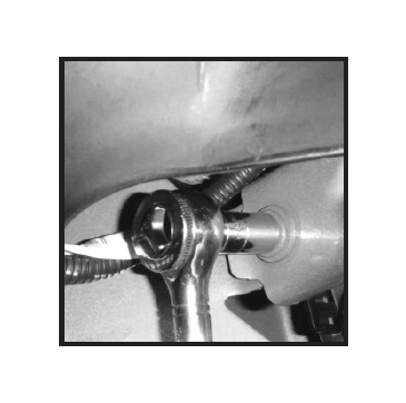
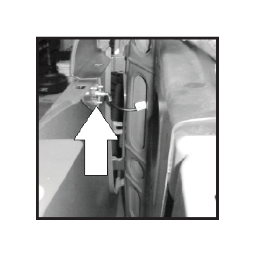
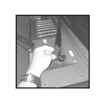
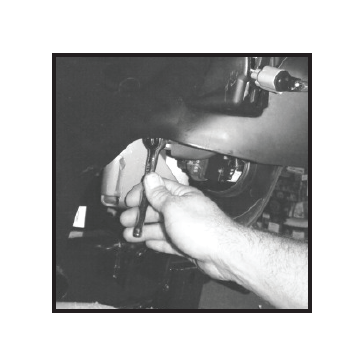
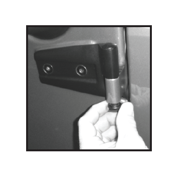
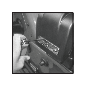
1- Remove RH windshield bracket. A T-40 socket will be required.
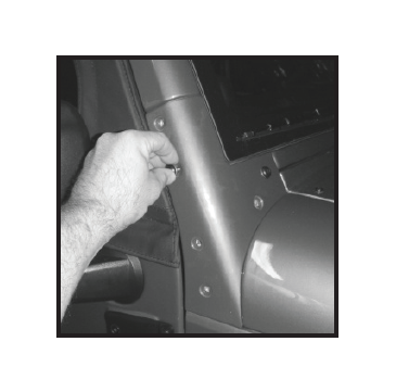
2 - Remove windshield bracket and set to the side.
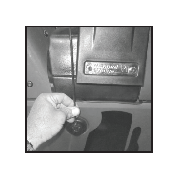
3 - Remove the (4) cowl screws. A T-30 Screw driver or socket will be required.
4 - Remove both wiper arms from vehicle.
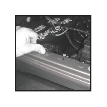
5 - Using a flat head screw driver carefully remove cowl center plastic retainer clips.
6 - Carefully remove cowl cover from vehicle.
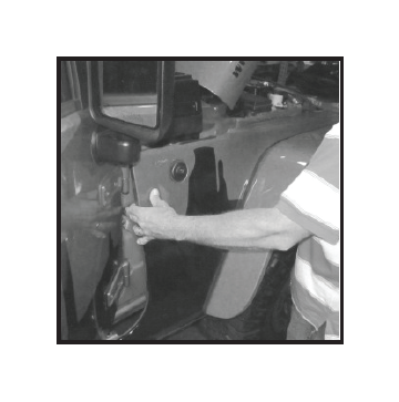
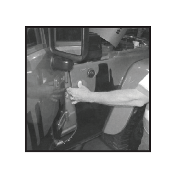
7 - Removal of front passenger side door is recommended. This will allow easy access to fender bolts. Follow owners manual for proper door removal steps. The help of a second person is recommended.
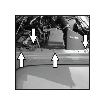
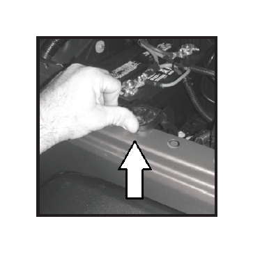
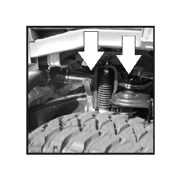
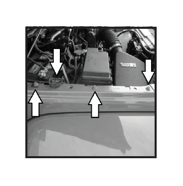
8 - Remove top four (10mm) fender bolts (arrows). Place bolts to the side noting location of each bolt. Bolts will be reused.
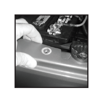
9 - Remove 2 inner cowl bolts located under cowl cover. note location of each bolt. Bolts will be reused.
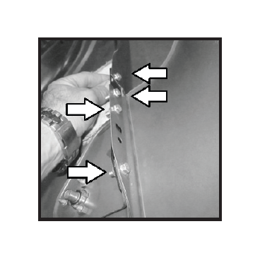
10 - Remove 6 inner fender bolts (arrows). Note location of bolts. Bolts will be reused.
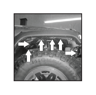
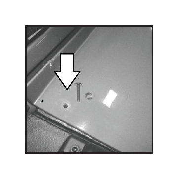
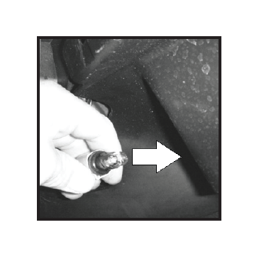
11- Following four images show locations of key inner fender bolts. Rear inner bolt may be recessed under inner fender liner. See arrow for bolt location.
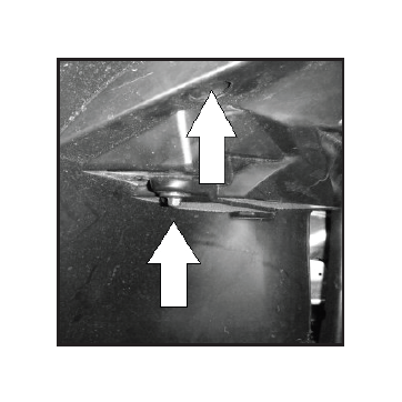
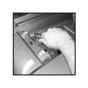
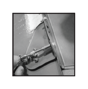
12 - Remove top fender support bolt.

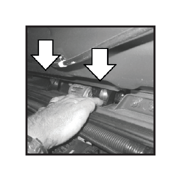
13 - Remove front inner bolt. Bolt is located under inner liner just behind front grill.
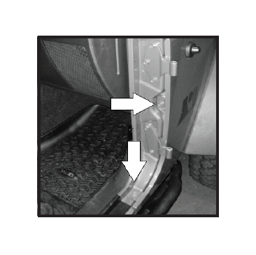
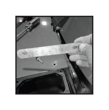
14 - Loosen inner door fender bolts. Do not remove. Allow enough clearance for fender to slide out easily. Notice: If door remains installed bolts should be removed to avoid damage to vehicle if door is closed.
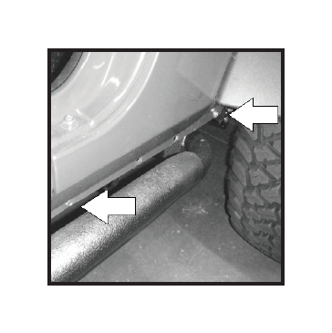
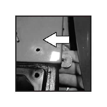
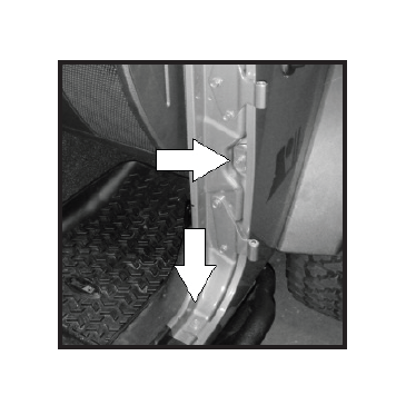
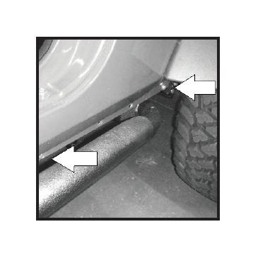
15 - Remove lower pinch weld fender bolts. Note location of bolts. Bolts will be reused NOTICE: On some models rock rails or side steps will need to be removed before bolts can be accessed.
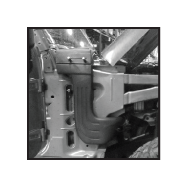
16 - Before proceeding check to see that all fender bolts have been removed and loosened as described in steps 7-15. Total of 13 bolts should have been removed and 2 loosened. Battery tray will need to be lifted up slightly and pushed up and away from fender (arrow).
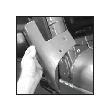
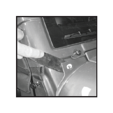
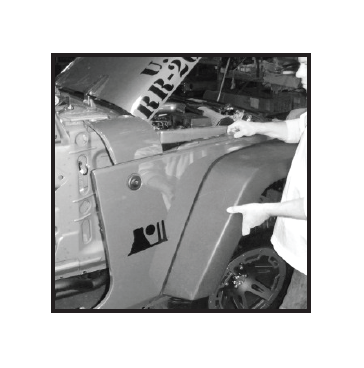
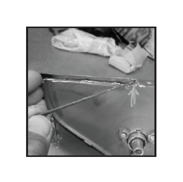
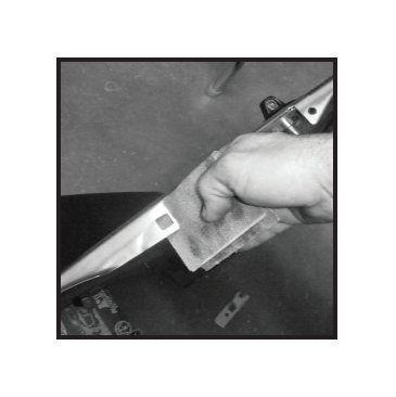
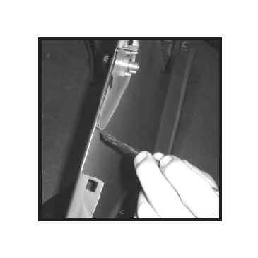
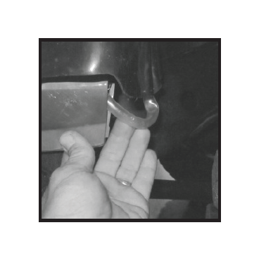
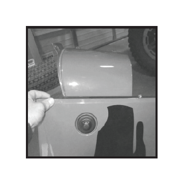
17- Top of rear fender will need to be lifted and cleared from inner mounting frame. If needed a small flat head screw driver can be used. Care must be taken to not bend the fender. Slide head of screw driver between the fender and frame. Carefully lift and pull fender too clear.
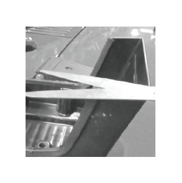
18 - Top cowl section of fender may be adhered to body. A small flat head screw driver or putty knife can be used to release cowl section from body. painters tape can be used to protect windshield paint if leverage is needed to release top cowl section.
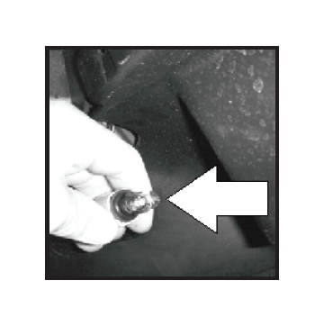
19 - Reach under plastic fender and disconnect side marker light. Socket can be removed by turning socket counter clockwise and pulling away from fender.
20 - Remove antenna mast from fender. With the assistance of another person pull fender away from vehicle just enough to disconnect antenna cable from fender.
21- Carefully lift fender up and away from vehicle. Watch front grill and inner door bolts as fender is removed. Fender must be raised and slid over inner fender support bracket noted in step 12.
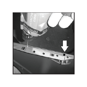
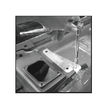
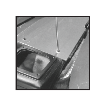
22- Fender should be supported to avoid damage. Locate the four spot welds securing removable upper cowl section to fender (arrows). Each spot weld will need to be removed.
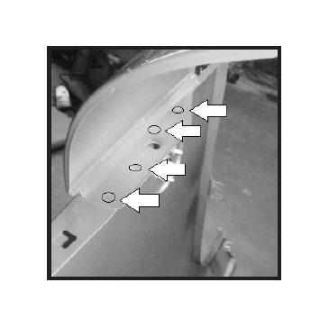
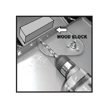
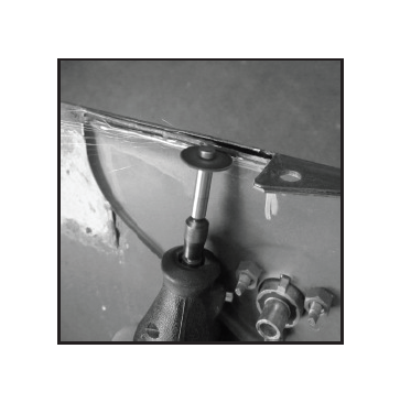
23- Using a small drill bit (1/8” is recommended) drill center guide holes into each spot weld as shown. A wood block should be placed inside of cowl as guide holes are drilled. This will reduce the chance of damage to cowl sheet metal.
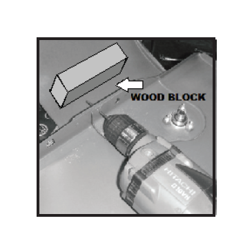
24- Enlarge the (4) 1/8” guide holes with a 5/16” bit. Carefully open guide holes making sure to place wood block over holes. Drill bits can grab thin sheet metal and shoot forward damaging fender. Increase hole size if needed.
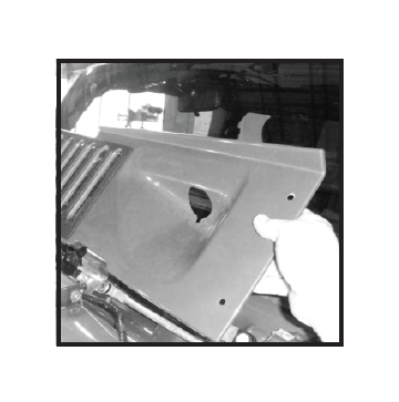
25- With spot welds cleared carefully remove upper cowl from fender.
NOTE: Fender can be damaged if welds have not been opened completely.
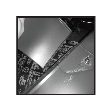
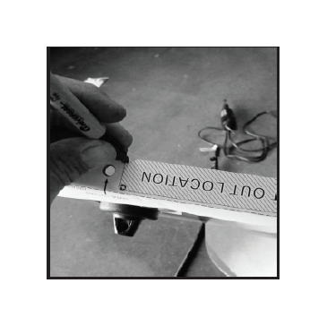
26- Cut out template from page 22. Place template over fender as shown. Templates should be folded along dotted line and guide cut outs removed.
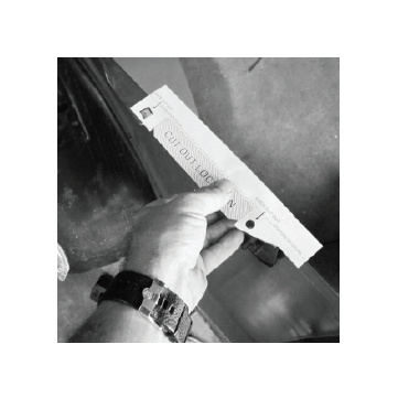
27- Align fold and guide cut outs on fender. Secure with tape. Mark holes on fender as shown. If template does not fit correctly refer to page 22 for instructions.
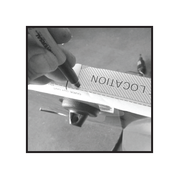
28 - Inner marks will be used to drill 7/32” cut line terminating holes. Notch marks will be used as cut starting points.
NOTE: Cut lines near outer face of fender must be 1/8” away from rolled edge. This will insure a clean installation and sealing surface to snorkel body.
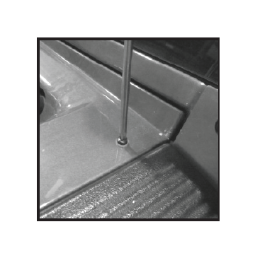
29- With guide holes marked and guide holes drawn drill 1/8” centering holes into fender. Use a 7/32” drill bit to enlarge 1/8” guide holes.
NOTICE: A wood block should be placed under marked hole as described in steps 23&24. Wood block will protect the fender if drill bit grabs panel.
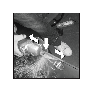
30 - Using a Dremmel tool or angle grinder fitted with a metal cutoff wheel cut fender along marked lines. Cut should start in the middle of outer cut line (arrow). Cut should be 1/8” away from rolled edge. Cut in each direction towards 7/32” terminating holes (arrows).
31 - Allow steel to cool before touching. Remove cut section from fender. Care should be taken when handling rough cut steel.
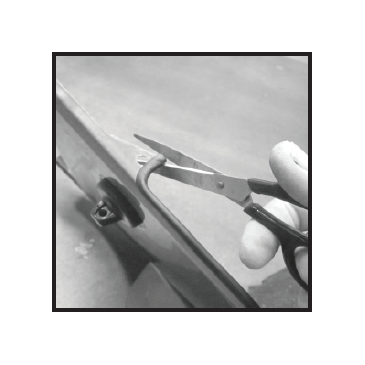
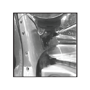
32 - Carefully trim extra metal from inner antenna support bracket as shown. DO NOT cut too deep or damage to outer fender may result. A Dremmel tool with a cut off wheel is recommended.
33- After cooling remove cut metal from fender. Care should be taken when handling rough cut metal. Removal of inner section will allow gasket to rest flush with fender.
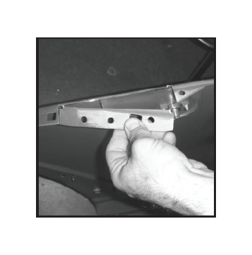
34- Test fit fender gasket as shown. Gasket should rest flat onto fender. If gasket does not fit flat around cut opening trim inner antenna bracket as needed.
35- With gasket in place test fit main body of snorkle into cut section as shown. Trim fender as needed. Avoid getting to close to the outer edge of fender. Trimming too far will result in a visible gap (arrow) .
36- Use 100 grit sand paper or sanding block to smooth rough cut metal.
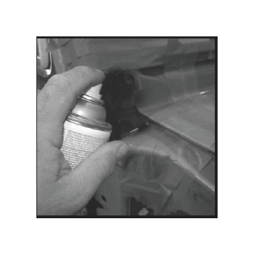
37- With opening trimmed to correct size and edges smoothed apply a protective coat of paint. Matching touch up paint is recommended. Clear coat can also be used.
38- Apply a very small amount of super glue to inner corners of fender gasket. It will be easier to start at on end and work around opening. Applying glue as needed. This will insure gasket remains in place during reasembly.
39- Trim extra gasket as needed.
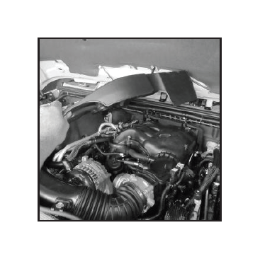
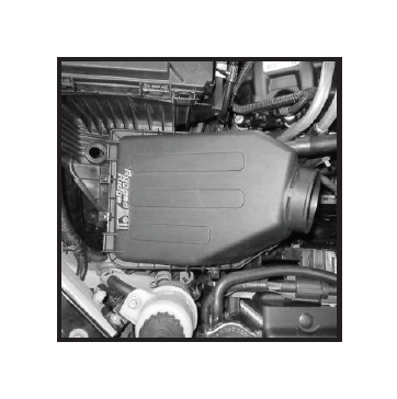
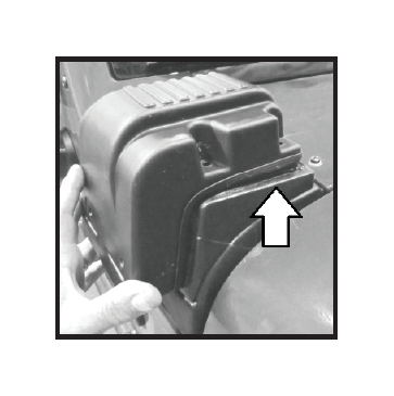
40- (NOTE: 3.6L application only)
Engine cover will need to
be removed on (3.6L)
equipped vehicles. Lift
up on front section of
cover and pull forward.
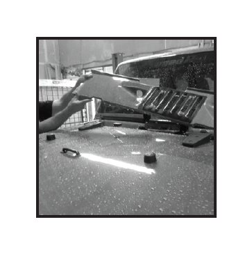
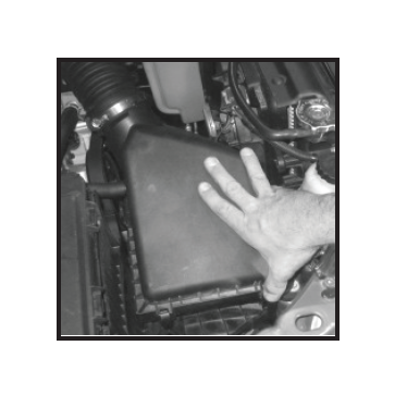
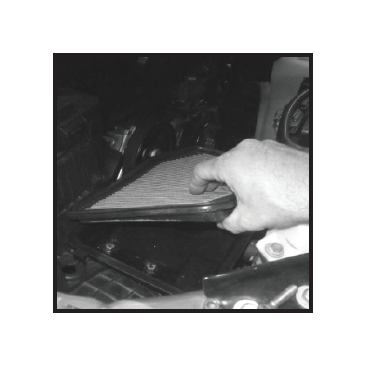
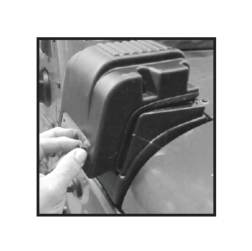
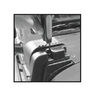
41 - Unlatch upper air box from lower air box. Remove factory air filter and set to the side. Filter can be reused if clean. A high flow aftermarket air filter is recommended for use with snorkel.
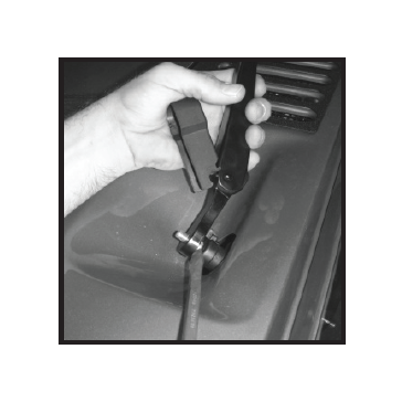
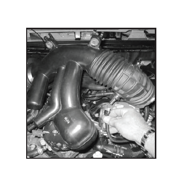
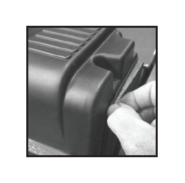
42 - Using a flat head screw driver loosen 3” hose clamps at intake and air box. (3.8L shown)
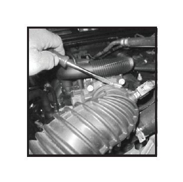
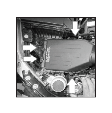
43 - (NOTE: 3.6L application only) Using a 10mm socket remove the two retainer bolts holding the (3.6L) air hose to the radiator. Do not discard bolts. They will be reused.
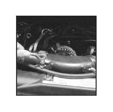
44 - Disconnect air tube from air box and intake. place to the side. Sensor wire may need to be disconnected.
(3.6L shown)
45 - Disconnect factory air intake tube from upper air box, place to the side. Upper air box will be reused. Do Not Discard.
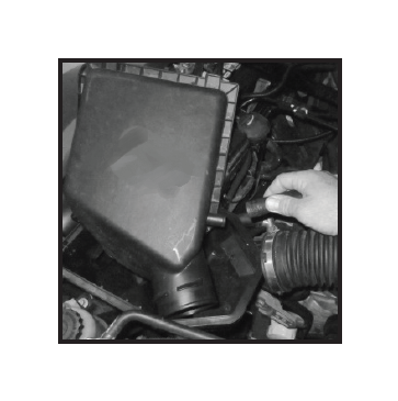
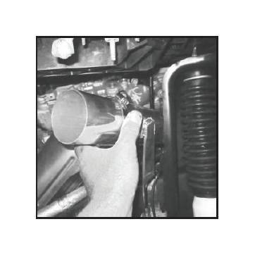
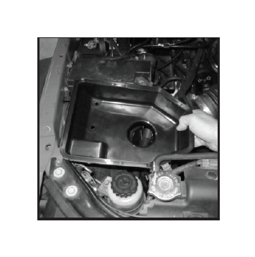
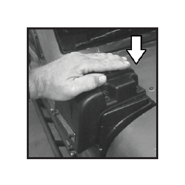
46- Remove lower air box from vehicle. Air box is held in place with location pins. Simply pull upwards and out of rubber retainer grommets.
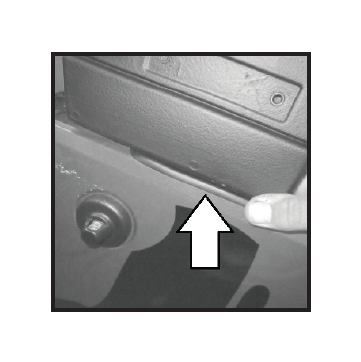
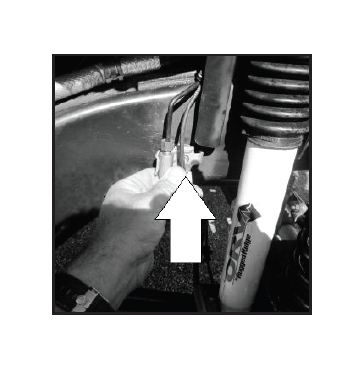
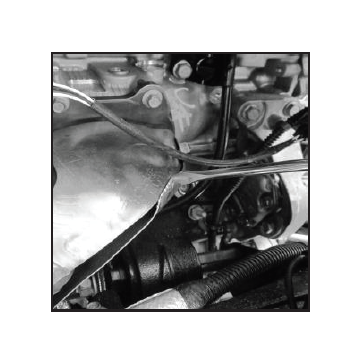
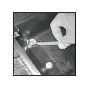
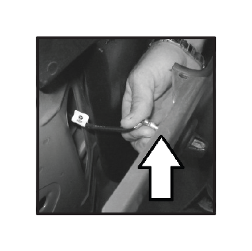
47- Locate 10mm bolt securing brake line bracket to left hand side of frame. (passenger side). Loosen bolt but do not remove.
48 - (NOTE: 3.6L Only) Inspect exhaust manifold heat shield. Shield may need to be clearanced to allow aluminum air tube to fit correctly.
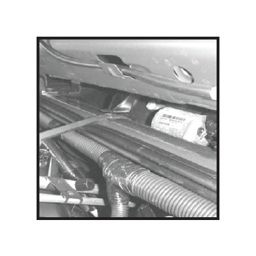
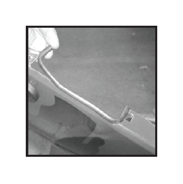
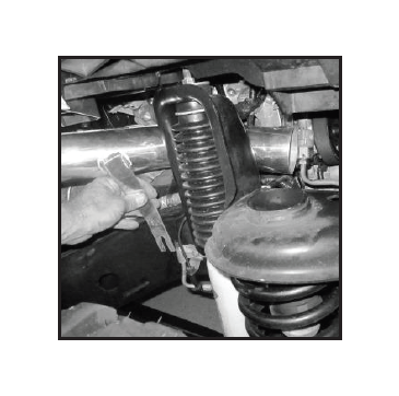
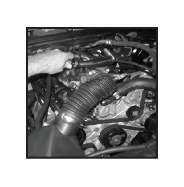
49- Insert aluminum air tube from fire wall forward between shock tower and engine. Front of tube will fit under power steering hard line and to the left of power steering pump. insert mounting tab behind brake bracket. (3.6L) Check heat shield clearance to tube.
50 - (NOTE: 3.6L Only) Remove air tube and make adjustments to heat shield as needed Upper and lower sections of heat shield can be rolled over as shown. A hammer and flat head screw driver can be used to make adjustments.
51 - With adjustments made insert tube and place mounting tab behind brake line mounting bracket. Secure 10mm bolt but do not tighten at this time. Final adjustment of air tube will be done later.
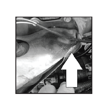
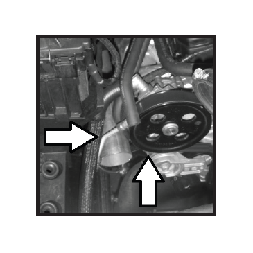
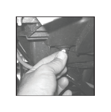
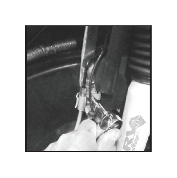
52- Inspect front of air tube. Tube should rest just under the power steering pump hard line and next to idler pulley (arrows). The power steering hard line can be moved if needed. Carefully grab the line and pull up for additional clearance. DO NOT OVER BEND LINE.
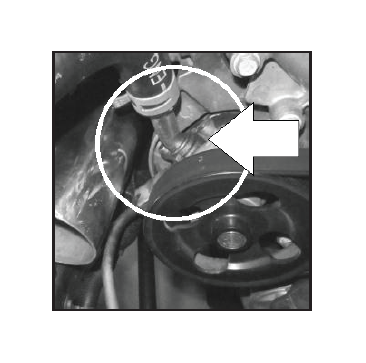
53- (Note: 3.8L & 3.6L) DO NOT pull or grab the low pressure power steering return line. If line is pulled or forced O-ring seal can be damaged. (3.6L shown).
54- Place 3” clamps onto both ends of aluminum air tube. Lower clamp should have screw face at the bottom of the tube facing outward as shown. The upper clamp should have screw face at the top facing outward.
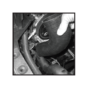
55- Place 90 degree silicone elbow onto aluminum air tube. DO NOT install 3” clamp. Test fit of
lower air box will be needed. Elbow will be removed prior to final assemble.
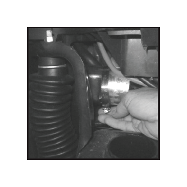
56- Place new lower air box onto elbow making sure elbow is fully seated to air box inlet. Air box should rest within 1/8” of rubber grommets.
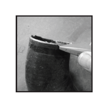
57 - If air box does not fit within 1/8” of rubber retainer grommets the top of the silicone air tube will need to be trimmed. Remove air box and elbow. If air box fits correctly proceed to step (59).
58 - Trim just enough of the silicone elbow for air box to rest within 1/8” of rubber grommets. Repeat step (56) making small adjustments to elbow until fit is correct.
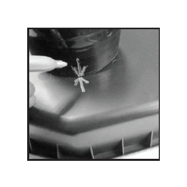
59- With lower air box in
correct location, 90 elbow attached to lower air box inlet, and aligned with aluminum air tube. Carefully remove air box and elbow together. Mark the position of elbow to air box. Remove elbow from air box.
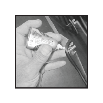
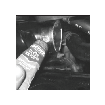
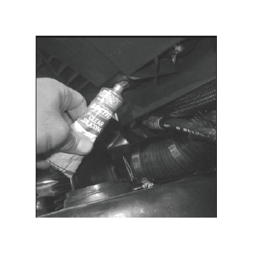
60- Apply a small amount of quality sealant to the inside of each end. Spread sealant evenly. A thin layer is all that will be needed for the inside to seal correctly. To much sealant can act like a lubricant during final assemble and cause tube to slide off inlet.
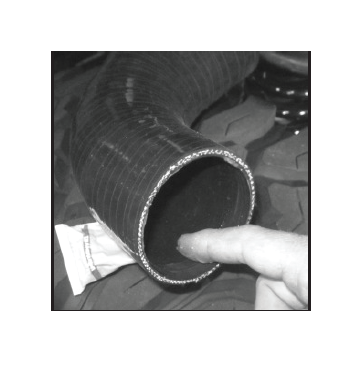
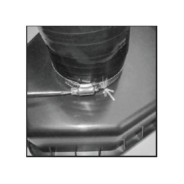
61 - Reinstall 90 deg elbow to lower air box. Align marks made in step (59). Slide 3” clamp onto elbow. With elbow placed against bottom face of lower air box tighten 3” clamp. Pull on elbow to insure it is secured tightly to inlet.
62 - add extra sealant to the inside lip of lower air box inlet and elbow as shown. Extra sealant can also be added to the outside as well.
63 - Apply a thin film of sealant around end of aluminum air tube. An excessive amount may cause the elbow to slide off air tube when tightened.
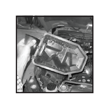
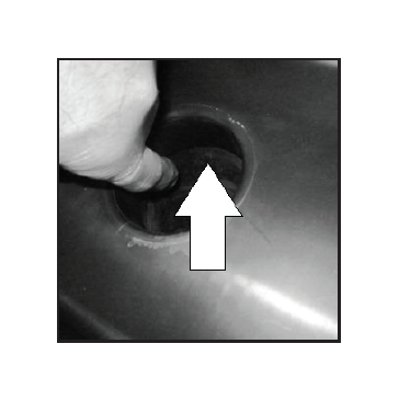
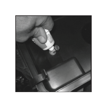
64 - Apply sealant to the
inside of two lower rubber grommets as shown. Make sure sealant completely fills the two holes.
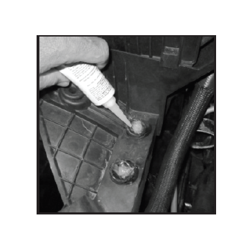
65 - Apply extra sealant to top of grommets.
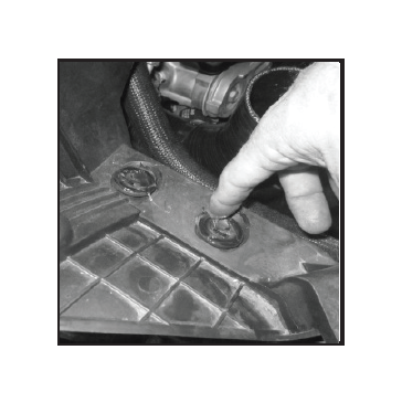
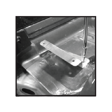
66 - Apply sealant to corresponding holes on the underside of inner fender mounting plate.
67 - Reinstall lower air box and 90 deg elbow. Slide elbow over aluminum air tube. Apply extra sealant around outer edge of the elbow and air tube. Slide 3” clamp over elbow but do not tighten at this time.
68 - Insert (2) M8 x 35 bolts with (2) M8 flat washers through lower air box mounting holes and rubber grommets. Apply a small amount of sealant to washers.
69 - Install (2) M8 nuts and (2) M8 flat washers to the underside of inner fender mounting plate. Add sealant if needed to insure a water tight seal.
70 - Tighten M8 hardware to secure new air box to vehicle. Inspect sealant around bolt heads and washers to insure there are no gaps. Smooth out sealant and clean off extra material.
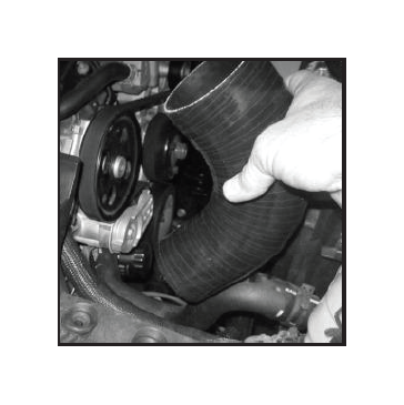
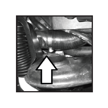
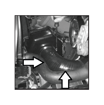
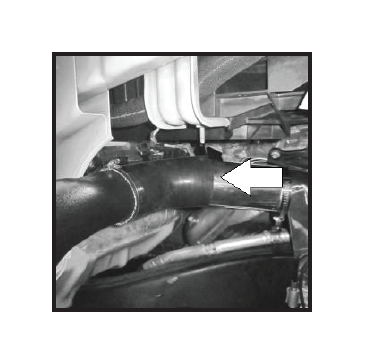
71 - Inspect 90 degree elbow around lower radiator hose. Elbow can have minor contact with radiator hose but should not be deformed or crushed. This will insure proper air flow to lower air box.
72 - Painting the area behind the removed windshield plate is recommended (black). Quality painters tape and paint should be used. Liberally apply tape
73 - Make sure painting is done in a well ventilated area. Paint should not be applied in a windy environment. This will insure overspray does not fall onto vehicle.
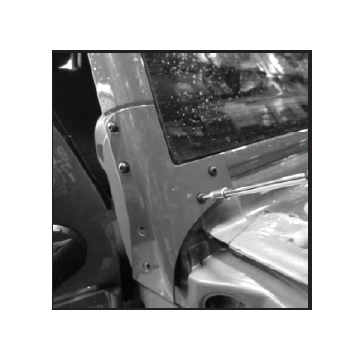
74 - Reinstall windshield bracket removed in step (2). Start and tighten the upper side M12 bolts and front M12 bolts as shown .
75 - If used, windshield light mounting brackets should be installed at this time. NOTE: the snorkel system has been designed to work with most Rugged Ridge components. Rugged Ridge cannot guarantee that other manufactures components will work or clear the XHD snorkel system.
76 - Install cowl “Z” bracket plate reusing factory at this time. in step (9). Secure the 10mm bolts removed bolts but do not tighten at this time.
77 - Apply a thin bead of sealant around the lower section of the snorkel main body. Spread sealant evenly around the outside of the outlet. Do not use excessive amount of sealant. A thin layer will insure a tight seal.
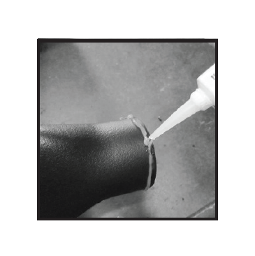
78 - Slide 45 deg elbow onto main body lower outlet. Secure 3” clamp around elbow Do Not tighten. Smooth and clean extra sealant from snorkel body.
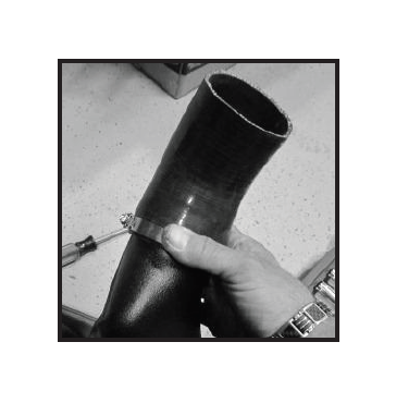
79 - Add a bead of sealant to the upper section of air tube (arrow). Slip main snorkel body and coupling over air tube as shown. Slide 3” clamp over 45 deg elbow but Do Not tighten.
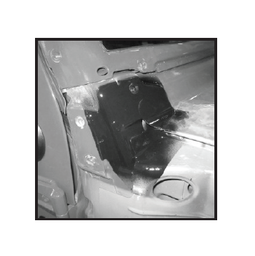
80 - Snorkel main body should rest in place as shown. Snorkel body should be fitted tight to inner frame. Make sure antenna cable is not hidden behind snorkel body.
81 - Inspect “Z”-bracket to snorkel alignment. Adjust snorkel body and “Z”-bracket to align mounting holes.
82 - Place windshield cowl cover back onto vehicle.
83 - Align driver’s side top holes and insert (2) M6 x20 Phillips head screws and washers. Secure but do not tighten.
84 - Check alignment of cowl cover and snorkel body. Insert M6 x 20 Phillips head screws to align cover, snorkel and “Z” bracket.
85 - With cowl cover removed tighten “Z”- bracket . Reinstall cowl cover and reinstall drivers side M6 x 20 screws and washers. Reattach center retainer clips removed in step (5).
86 - Locate cowl nut plate. Nut plate is used to secure cowl cover and snorkel body to “Z” bracket.
87 - Slide nut plate under snorkel body as shown. Working from engine compartment align mounting holes. Start one M6 Phillips head screw to hold in place.
88 - Secure all (4) M6 cowl mounting screws. Make sure M6 black washers are placed under M6 screws before tightening.
89 - Reinstall wiper arms removed in step (4).
90 - With main body installed inspect aluminum air tube. Tighten 10mm bolt at air tube mount and brake bracket. (Note: 3.6L) Inspect clearance to heat shield.
91 - (Note: 3.6L Only) Tube can be adjusted if additional clearance to heat shield is needed. Grab tube and bend as needed. Make sure lower section of air tube still clears power steering pump and hose (arrows).
92 - Tighten all 3” hose clamps.
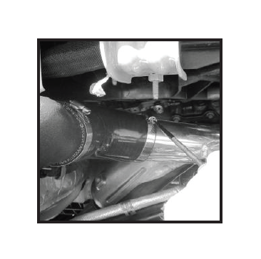
93 - Slide 3/8” drain hose and 3/8” clamp to bottom of snorkel body.
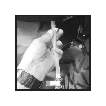
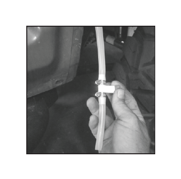
94 - Hose should be cut into two lengths. Top section should be about 8” long. The lower section will be 4” and trimmed as needed. Connect 3/8” clamps to valve and tighten all (3) clamps.
95 - Drain should be checked before fender is installed. Open and close valve. Drain should be lowered and checked to remove any excess water on a regular basis.
96 - Reinstall air filter removed in step (41). It is recommended that a high flow air filter be used. Either a washable (oil free) design like Rugged Ridge P/N: 17752.05 or K&N oil type can be used.
97- Reinstall factory upper air box removed in step (41). Rotate air hose back to upper air box and connect 3” clamps. Connect vent wire harness.
98- Adjust (4) air box sealing clamps full open. Clamps are designed to slip under lower air box flange and over flange and ribs of upper OE air box. Clamps are to be placed as shown (arrows). Check fitment of air box and tighten clamps DO NOT OVER TIGHTEN.
99 - Tighten all clamps and inspect sensor connections. Air sensor must be in place before vehicle is started. (3.8L shown).
100 - Reinstall fender. Notice: The help of a second person is recommended. Before installing fender to vehicle make sure antenna cable is attached to fender antenna mount.
101 - Slide fender up & over fender support bracket (noted in step (12). Inspect area around snorkel body. Fender should fit tight to seal but should not be forced to align with fender mounting holes. If fender opening needs to be trimmed for better fit refer to steps (30) through (36).
102 - Align inner door fender tabs with door bolts. Slide tabs under bolts and secure but do not tighten at this time.
103 - Align lower fender holes with pinch weld mounting holes. Reuse bolts removed in step (15). Secure bolts but do not tighten at this time.
104 - Secure top of fender to inner fender frame. Battery tray support will need to be lifted to allow fender to slide under support.
105 - Reinstall all remaining bolts removed in steps (8) through (13). Secure all bolts but do not tighten at this time.
106 - With all 13 bolts secured double check alignment of fender. Tighten all bolts.
107 - Reattach side marker bulb to inside of fender flare. To secure bulb turn socket clockwise.
108 - If door was removed reinstall and secure with factory door torx nuts. Side steps or rock rails should be reinstalled at this time. The help of a second person is recommended.
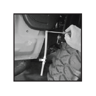
109 - Tuck drain tube up behind inner fender liner and between lower fender and inner pinch weld. as shown.
110 - Add “U” gasket to low mount intake if not already installed to snorkel main body. Starting from lower intake edge work around the intake making sure gasket is fitted tight to intake. Trim gasket if needed.
111 - Rest lower intake onto snorkel body as shown. lower (long) M6 caps head bolts will be started first.
112 - Insert plastic spacers between snorkel body and intake. Insert M6 x 55mm caps head bolts through logo plate. Start threads but do tighten.
113 - Press top of intake down onto snorkel body.
114 - Using (4) M6 short caps head bolts and (4) M6 flat washers secure intake to snorkel body.
115 - With intake secure pull outer edge of “U” gasket away from intake until gasket rest flat against side of intake.
116 - Tighten all (6) caps head bolts. Do Not Over Tighten. A firm seal is all that is required.
117 - Reinstall antenna mast.
Snorkel Installation Instructions: 2007-2013 Wrangler 2DR & 4DR Unlimited
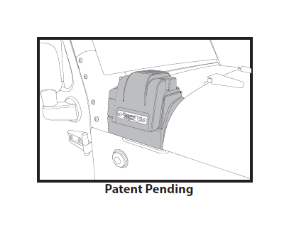
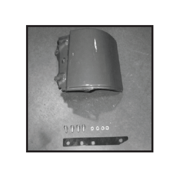
1 - Snorkel kit includes a cowl remount bracket. The bracket will allow snorkel to be removed and factory upper fender cowl bolted back into stock location.
2 - Fender and snorkel will need to be removed from vehicle. Refer to steps (1) through (21) of snorkel installation instructions for fender removal.
3 - Align bracket to the holes of upper fender cowl plate and fender. Plate will be placed under fender as shown.
4 - Cowl should be aligned with outer edge of fender.
5 - Tighten M6 hex head bolt and nuts before reinstalling fender on vehicle.
6 - Installation of fender is the reversal of steps (1) through (21) of the snorkel installation instructions. Reinstall windshield bracket.