FREE 1 to 3-Day Delivery on Orders $149+ Details

How to Install Rugged Ridge Heavy Duty Crossover Steering Conversion Kit (97-06 4.0L Wrangler TJ) on your Jeep Wrangler

Shop Parts in this Guide
Contents:
1. Short Tube H/D I .25" ( I) (Not Sold Separately)
2. Long Tube H/D I .25" ( I ) (Not Sold Separately)
3. 18040.50 - Damper Bracket ( I )
4. 18043.26 - Tie Rod End H/D 718" RH Thread (2)
5. 18043. I 0 - Tie Rod End H/D 718" LH Thread ( I )
6. 18043.27 - Tie Rod End, Cross Over H/D 718" LH Thread ( I ) `
7. I 8050.86 - Thread Clamp H/D (4)
THIS KIT HAS BEEN DESIGNED FOR USE WITH LIFTED VEHICLES BETWEEN 2" TO 4" OF LIFT.
INTRODUCTION
Thanks for your Rugged Ridge* purchase. The components in this kit are intended to improve the Off-road capability and durability of your Jeep* factory tie-rod and cast steering linkage. If you are a committed off reader, consider this cross-over steering system as one important part of your overall suspension build-up. The Jeep* suspension design and wide range of after-market suspension components, tires, and wheels used by off road enthusiasts requires special attention to instructions regarding the installation and adjustment of this kit and overall consideration in the selection and compatibility of your suspension set-up with this kit. Depending on the height and configuration of your suspension, you may need to adjust or purchase additional components to assure desired steering characteristics and reduce degraded steering feedback caused by high-angle inputs between the pitman arm, drag link and HD tie-rod and cast linkage supplied with this kit. Depending on your Jeep* experience and mechanical ski\Is, Rugged Ridge* recommends seeking advice from or having this kit installed by a qualified off-road mechanic who can inspect your suspension build, adjust steering components and set alignment to optimize your steering system and the features of this kit. If you have remaining technical questions after reading these instructions we are here to help. Contact us toll free at ( I -800-449-6649).
Product Safety Information
We want you to safely enjoy our products and your off-road Jeep* experience. Throughout these instructions important safety information is generally preceded by one of three signal words indicating the relative risk of injury. The signal words mean:
! WARNING: A hazardous situation which, if not avoided, could result in death or serious injury. You can be Killed or Seriously Hurt if you don't follow instructions.
! CAUTION: A hazardous situation which, if not avoided, could result in minor or moderate injury. You can be moderately HURT and also may suffer property damage if you don't follow instructions.
NOTICE: Careful attention is required to this instruction or operation but does generally not relate to personal injury. Damage to your product or other property may result if you don't follow instructions.
WARNINGS!
- Use of adjustable drag link and drop pitman arm may be required for vehicles with over a 2" lift and is strongly recommended for suspension builds over 4". This kit has been designed for vehicles with up to a 4" suspension lift. (Drop pitman arm, Rugged Ridge@ part # 18006.54 - XJ/ZJ or 18006.50 87-06 Wrangler).
- Tie-rod end wear and required maintenance will vary depending on your suspension configuration and vehicle use. Select and adjust pitman arm, drag|ink and tie rod to minimize input angle between drag link and tie rod. Routinely inspect tie rod ends for wear, and thread clamps for proper torque and security. Do not use if kit parts are damaged or trail-repaired using high heat.
- During installation, Keep wheels and steering components centered. Before use, assure your wheel/tire choice is properly balanced and vehicle professionally aligned. Read and follow all instructions and warnings accompanying this product and those in your Jeep@ owners manual and Off Road Driving Supplement.
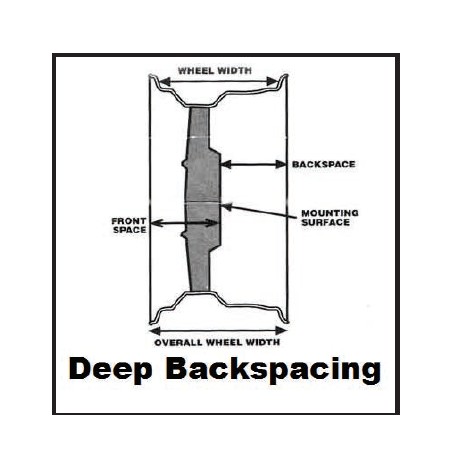
- Strength, size and attachment points of tie-rod and steering linkage require additional wheel clearance. HD Cross-Over Steering System is generally not compatible with smaller OEM steel wheels or wheels with a deep backspacing. Before installation, use assembled tie rod for preliminary check of expected wheel/tire clearance during full sweep of steering. Perform post-installation inspection as instructed below. Do not use if tie-rod contacts any portion of wheel/tire.
WARNINGS!
- Use of adjustable drag link and drop pitman arm may be required for vehicles with over a 2" lift and is strongly recommended for suspension builds over 4". This kit has been designed for vehicles with up to a 4" suspension lift. (Drop pitman arm, Rugged Ridge@ part # 18006.54 - XJ/ZJ or 18006.50 87-06 Wrangler).
- Tie-rod end wear and required maintenance will vary depending on your suspension configuration and vehicle use. Select and adjust pitman arm, drag|ink and tie rod to minimize input angle between drag link and tie rod. Routinely inspect tie rod ends for wear, and thread clamps for proper torque and security. Do not use if kit parts are damaged or trail-repaired using high heat.
- During installation, Keep wheels and steering components centered. Before use, assure your wheel/tire choice is properly balanced and vehicle professionally aligned. Read and follow all instructions and warnings accompanying this product and those in your Jeep@ owners manual and Off Road Driving Supplement.
- Strength, size and attachment points of tie-rod and steering linkage require additional wheel clearance. HD Cross-Over Steering System is generally not compatible with smaller OEM steel wheels or wheels with a deep backspacing. Before installation, use assembled tie rod for preliminary check of expected wheel/tire clearance during full sweep of steering. Perform post-installation inspection as instructed below. Do not use if tie-rod contacts any portion of wheel/tire.
INSTALLATION
! WARNING: Properly secure vehicle. Place in gear or park and set emergency brake. For further safety, block tires. Use safety glasses and gloves.
Step I . Remove old steering linkage. Start by centering wheels and running a tape measure from passenger side Knuckle (inner) to driver's side Knuckle (inner) and carefully record distance. If knuckles are moved by accident you will be able to return to the approximate centered position by using this measurement. Use best efforts to NOT alter the position of the front wheels or steering wheel during the removal or subsequent installation. Keeping these components in the original position aids in approximating your initial front end alignment settings.
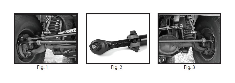
Step 2. Attach H/D Cross-Over steering as shown below (Fig. I ). The dual attachment point tie-rod end should be mounted to the passenger side Knuckle. By turning the H/D center tubes clock-wise or counter-clockwise adjustments to the lengths can be made. Adjust until all mounting holes are aligned. Attach castle nuts and torque to 6Oft-lbs for all locations.
WARNING!: Assure there are a minimum of 5, properly engaged tie-rod threads captured in each leaf the center tube.
INSTALLATION
! WARNING: Properly secure vehicle. Place in gear or park and set emergency brake. For further safety, block tires. Use safety glasses and gloves.
Step I . Remove old steering linkage. Start by centering wheels and running a tape measure from passenger side Knuckle (inner) to driver's side Knuckle (inner) and carefully record distance. If knuckles are moved by accident you will be able to return to the approximate centered position by using this measurement. Use best efforts to NOT alter the position of the front wheels or steering wheel during the removal or subsequent installation. Keeping these components in the original position aids in approximating your initial front end alignment settings.
Step 2. Attach H/D Cross-Over steering as shown below (Fig. I ). The dual attachment point tie-rod end should be mounted to the passenger side Knuckle. By turning the H/D center tubes clock-wise or counter-clockwise adjustments to the lengths can be made. Adjust until all mounting holes are aligned. Attach castle nuts and torque to 6Oft-lbs for all locations.
WARNING!: Assure there are a minimum of 5, properly engaged tie-rod threads captured in each leaf the center tube.
Step 3. Insert cotter pins into tie rod and castle nuts. Install all grease fittings and if needed add grease.
NOTICE!: DO NOT over fill dust boots with grease. Stop adding grease at the first signs of grease escaping past dust boots. Remove grease fitting and install grease plugs in tie rod ends.
Step 4. With stabilizer mounted and positioned correctly, tighten u-bolt nuts. Install stabilizer nut and tighten to 45ft-lbs.
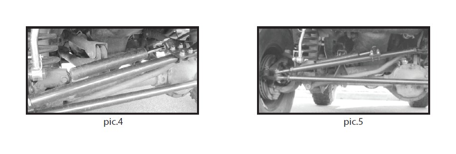
Step 5. Attach H/D steering stabilizer mounting bracket to drag link tube (pie 4 & 5). Reattach the stabilizer and check clearance to the oil pan. Bracket should allow full movement of the stabilizer when in use (left to right as steering is cycled). NOTE: If factory stabilizer is reused the mounting bolt will need to be cut off destabilize. Supplied bolt for stabilizer bracketcanthee used.
Step 3. Insert cotter pins into tie rod and castle nuts. Install all grease fittings and if needed add grease.
NOTICE!: DO NOT over fill dust boots with grease. Stop adding grease at the first signs of grease escaping past dust boots. Remove grease fitting and install grease plugs in tie rod ends.
Step 4. With stabilizer mounted and positioned correctly, tighten u-bolt nuts. Install stabilizer nut and tighten to 45ft-lbs.
Step 5. Attach H/D steering stabilizer mounting bracket to drag link tube (pie 4 & 5). Reattach the stabilizer and check clearance to the oil pan. Bracket should allow full movement of the stabilizer when in use (left to right as steering is cycled). NOTE: If factory stabilizer is reused the mounting bolt will need to be cut off destabilize. Supplied bolt for stabilizer bracketcanthee used.
NOTE: Mounting bracket orientation may not match images supplied. The correct placement will need to be determined on each vehicle to allow clearance of oil pan and sway bar mounting brackets.
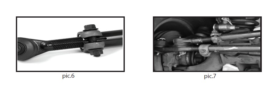
Step 6. With steering wheel and steering Knuckles aligned and castle nuts tightened align the tube clamps as shown in pic. 6.
Step 7. The clamp must be located as close the the end of the tube as possible. The clamp bolt should be located directly over the tube cutout. Torque clamps to 35 ft/lbs.
NOTE: Mounting bracket orientation may not match images supplied. The correct placement will need to be determined on each vehicle to allow clearance of oil pan and sway bar mounting brackets.
Step 6. With steering wheel and steering Knuckles aligned and castle nuts tightened align the tube clamps as shown in pic. 6.
Step 7. The clamp must be located as close the the end of the tube as possible. The clamp bolt should be located directly over the tube cutout. Torque clamps to 35 ft/lbs.
Step 8. Check all clamps once assembly is complete to ensure proper torques are achieved. If clamps become loose, tubes can rotate and allow vehicle to come out of alignment.
Step 9. (ALL APPLICATIONS) Complete installation by corl6rming during suspension travel and full steering sweep: (A.) no interference between HD cross-over components and other steering components, (B.) NO CONTACT BETWEEN tie-rod ends and wheels/tires, (C.) front wheels centered in relation to neutral point of steering wheel and wheels tracking parallel and equal during right and left turns. If necessary, adjust steering components per Jeep* service manual or with assistance of qualified off-road mechanic.
Step 10. (ALL APPLICATIONS) Inspect all castle nuts and clamps before test driving vehicle. After completing safety inspection proceed with road test (avoid traffic if possible). If adjustments are needed review step 2. Tighten all clamps once adjustments are made.
WARNING!:
Do not rely upon installation measurements for final alignment. Installation of HD cross-over conversion requires professionalfront alignment to recommended seHings. Inspect and re-torque all fasteners in HO cross-over conversion after first 25 miles and each off road use.
TROUBLESHOOTING
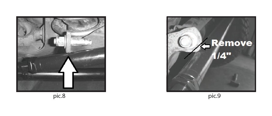
- On lifted vehicles trimming of sway bar mounting brackets may be required. With kit installed cycle suspension at full drop. Tum steering wheel to the right and check to see if drag link t ube makes contact with sway bar mounting bracket (pic.8). If tube contacts bracket trim bracket back about 1/4" (pic.9).
TROUBLESHOOTING
- On lifted vehicles trimming of sway bar mounting brackets may be required. With kit installed cycle suspension at full drop. Tum steering wheel to the right and check to see if drag link t ube makes contact with sway bar mounting bracket (pic.8). If tube contacts bracket trim bracket back about 1/4" (pic.9).
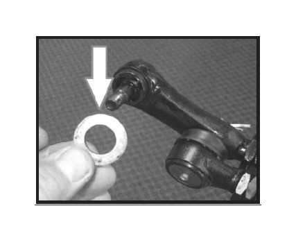
For dead spots in steering a large Bat washer has been supplied with this kit, this washer can be used between the steering Knuckle and tie rod end. This washer reduces the movement of the tie rod end to reduce end play during steering direction change. This dead spot is caused by the angle of the drag link and not the steering system. If dead spot remains, further modi6cation to vehicle will be needed. All steering IinKages and tracK bars should remain as parallel as possible to maintain a safe vehicle.
For dead spots in steering a large Bat washer has been supplied with this kit, this washer can be used between the steering Knuckle and tie rod end. This washer reduces the movement of the tie rod end to reduce end play during steering direction change. This dead spot is caused by the angle of the drag link and not the steering system. If dead spot remains, further modi6cation to vehicle will be needed. All steering IinKages and tracK bars should remain as parallel as possible to maintain a safe vehicle.