 FREE 1 to 3-Day Delivery on Orders $149+ Details

How to Install a Rugged Ridge Front and Rear Control Arm 4 piece Skid Plate Kit on your Wrangler

Shop Parts in this Guide
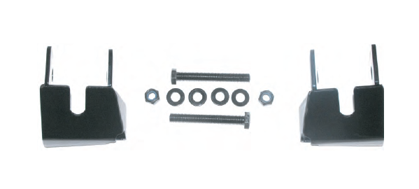
Contents: (2) Universal front skid plate brackets
(2) M14-2.00 x 120 graded bolt
(2) M14-2.00 Lock Nut
(4) M14 Washer
(4) M14 Spacer
Contents: (2) Universal front skid plate brackets
(2) M14-2.00 x 120 graded bolt
(2) M14-2.00 Lock Nut
(4) M14 Washer
(4) M14 Spacer
1. Please read instructions fully prior to installing the JK Front Control Arm Skid Plates (18003.35). The skid plates have been designed to be a no drill application for ease of installation. Take your time when installing to insure proper fitment and tightening of bolts. will not fit vehicles equipped with alignment cams.
1. Please read instructions fully prior to installing the JK Front Control Arm Skid Plates (18003.35). The skid plates have been designed to be a no drill application for ease of installation. Take your time when installing to insure proper fitment and tightening of bolts. will not fit vehicles equipped with alignment cams.
2. Put vehicle in gear, set the emergency brake and block tires before proceeding with installation.
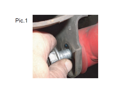
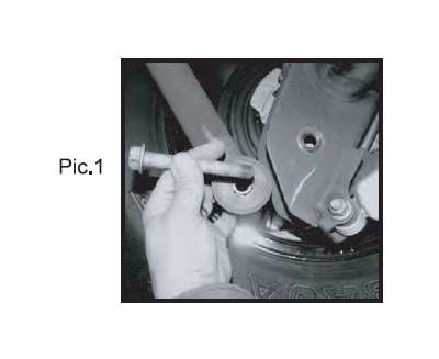
3. Support lower control arm and remove original axle bracket attachment bolt and nut (pic.1)
2. Put vehicle in gear, set the emergency brake and block tires before proceeding with installation.
3. Support lower control arm and remove original axle bracket attachment bolt and nut (pic.1)
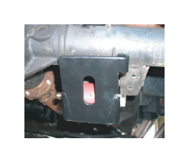
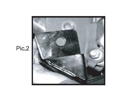
4. Place skid plate over axle bracket as shown. Please that these brackets are universal in regards to the left side (drivers side) and right side (passenger side) axle brackets. Place tab over axle bracket and align skid plate mounting holes with axle bracket mounting holes
4. Place skid plate over axle bracket as shown. Please that these brackets are universal in regards to the left side (drivers side) and right side (passenger side) axle brackets. Place tab over axle bracket and align skid plate mounting holes with axle bracket mounting holes
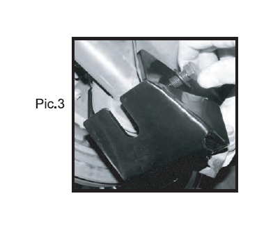
5. Insert one of the 4 spacers provided on each side of of the bracket. Place control arm back into axle bracket and attach skid plate with supplied M14 bolt, washer, and nut (Pic.3).
6. Tighten nut and bolt to 130 ft. lbs.
7. Repeat steps 2-6 for the other side. After installing both side double check that both bolts have been tightened to the specified setting of 130 ft. lbs.
8. After 200 miles inspect all bolts and tighten to 130 ft. lbs. if needed
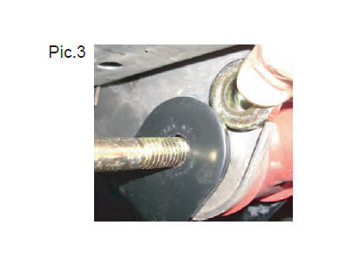
Contents:
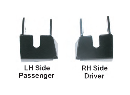
(1) Right Rear Skid Plate
(1) Left Rear Skid Plate
(4) M14 Flat Washer
(2) M14 Nylock Hex Nut
(2) M14 - 20 x 120 Graded Bolt
Contents:
(1) Right Rear Skid Plate
(1) Left Rear Skid Plate
(4) M14 Flat Washer
(2) M14 Nylock Hex Nut
(2) M14 - 20 x 120 Graded Bolt
1. Please read instructions fully prior to installing the JK Rear Control Arm Skid Plates (18003.36). The Skid Plates have been designed to be a no drill application for ease of installation. Take your time when installing to insure proper fitment and tightening of bolts.
PLEASE NOTE: This kit will not fit vehicles equipped with alignment cams or cam bolts.
2. Put vehicle in gear (Park), set emergency brake and block tires before proceeding with installation.
3. Support lower control arm and remove original 14mm axle control arm attachment bolt and nut (pic.1).
2. Put vehicle in gear (Park), set emergency brake and block tires before proceeding with installation.
3. Support lower control arm and remove original 14mm axle control arm attachment bolt and nut (pic.1).
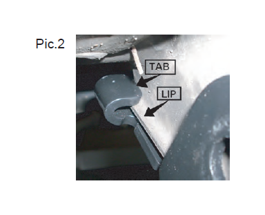
4. Place control arm back into mounting bracket and slide control arm skid plate up and over mounting bracket from underneath (pic.2).
4. Place control arm back into mounting bracket and slide control arm skid plate up and over mounting bracket from underneath (pic.2).
5. Align mounting holes of the control arm, mounting bracket and control arm skid plate. With one flat washer placed on M14 bolt insert through side opposite from tire. Place one flat washer and M14 Nylock nut on to bolt and tighten to 130 ft. lbs. (pic.3)
5. Align mounting holes of the control arm, mounting bracket and control arm skid plate. With one flat washer placed on M14 bolt insert through side opposite from tire. Place one flat washer and M14 Nylock nut on to bolt and tighten to 130 ft. lbs. (pic.3)
6. Repeat steps 2-5 for the other side. After installing both sides double-check that both bolts have been tightened to the specified setting of 130 ft. lbs. If vehicle is equipped with greasable control arms servicing them at this time is recommended.
7. After 200 miles inspect all bolts and tighten to 130 ft. lbs. if needed.

