 FREE 1 to 3-Day Delivery on Orders $149+ Details

How to Install Rugged Ridge Dual Battery Relay Kit on your 87-18 Jeep Wrangler YJ, TJ, JK & JL
Installation Time
1 hours
Tools Required
- Socket Wrench
- 8mm Socket
- 10mm Socket
- 12mm Socket
- 14mm Socket
- 8mm Nut (2) (optional for mounting)
- 8mm Bolt (2) (optional for mounting)
- 3" x 5" Sheet Metal (optional for mounting)

Shop Parts in this Guide
Note: This installation requires a solid mounting of the isolator relay. Due to layout, fabrication of a mounting surface is almost essential for proper installation. When choosing a mounting location, ensure that the isolator relay is within cable-reach of both batteries and does not touch the hood surface when the hood is closed.
Installation Instructions:
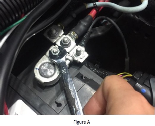
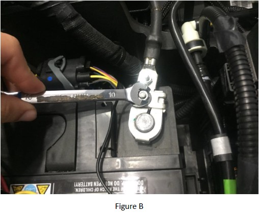
1. Disconnect the battery cables from the positive (Figure A) and negative (Figure B) terminals using 10mm socket wrench.
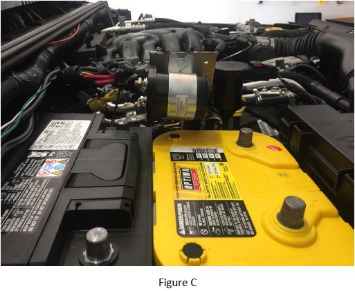
2. Mount the isolator relay onto the linear purge valve mounting tab of the dual battery tray or fabricate a flat surface to mount the isolator relay to (optional) (Figure C).
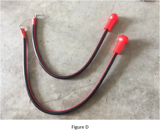
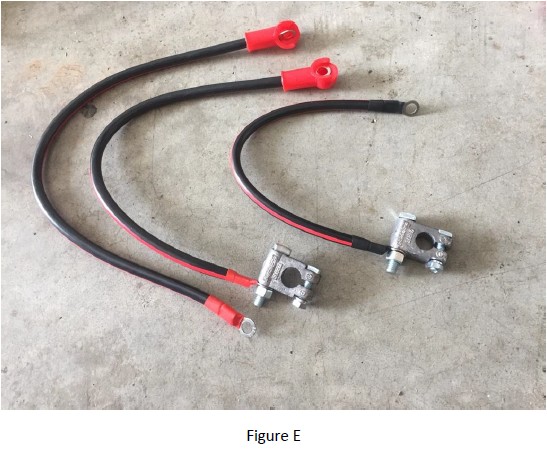
3. Place the terminal covers on both red battery jumpers (Figure D).
4. Install the positive terminal clamp on the short red battery jumper and the negative terminal clamp on the black battery jumper (Figure E).
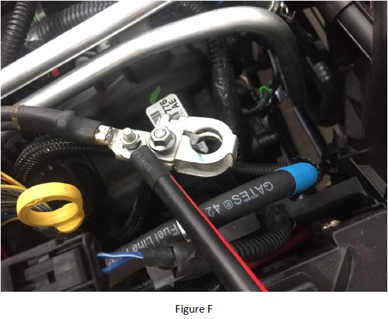
5. Connect the black battery jumper to the negative terminal of the main battery using 10mm socket wrench (Figure F).
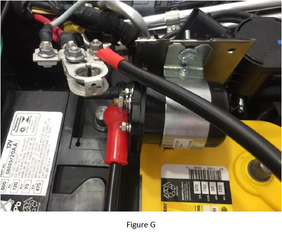
6. Connect the long red battery jumper to the positive terminal of the main battery using 10mm socket wrench and terminal one on the isolator relay using 14mm socket wrench (Figure G).
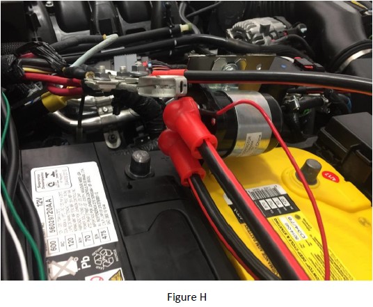
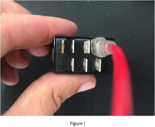
7. Connect the short red battery jumper to terminal two on the isolator relay using 14mm socket wrench and connect the switch-isolator relay wire with big ring terminal to terminal two on the isolator relay using 14mm socket wrench (Figure H) and A4 on the three position switch (Figure I).
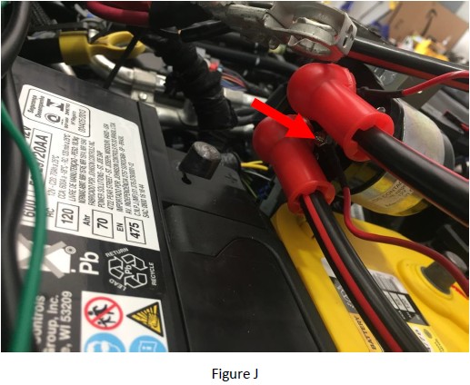
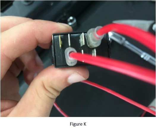
8. Connect the switch-isolator relay wire with the small ring terminal to the positive terminal on the isolator relay using 8mm socket wrench (Figure J) and B2 on the three position switch (Figure K).
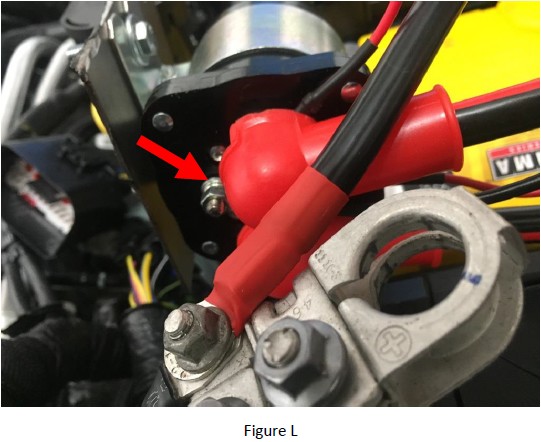
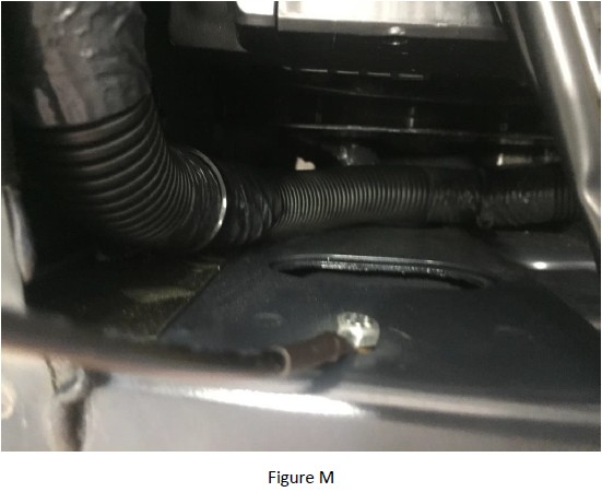
9. Connect the isolator relay ground wire to the negative terminal on the isolator relay using 8mm socket wrench (Figure L) and ground within the engine bay (Figure M).
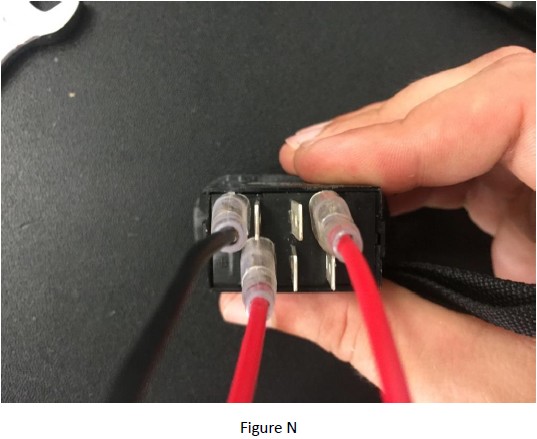
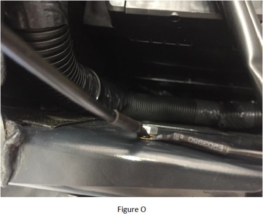
10. Connect the switch ground wire to A1 on the three position switch (Figure N) and ground within the engine bay (Figure O).
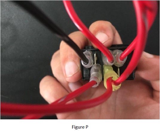
11. Connect the switch power wire to A3 and B3 on the three position switch (Figure P) and to a 12v power source. Note: Choose a constant (rather than switched) 12v power source if you plan to utilize your auxiliary battery with the vehicle not running.
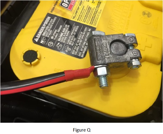
12. Connect the short red battery jumper to the positive terminal of the auxiliary battery using 12mm socket wrench (Figure Q).
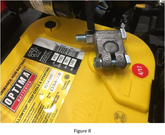
13. Connect the black battery jumper to the negative terminal on the auxiliary battery using 12mm socket wrench (Figure R).
14. Reconnect the negative cable to the main battery negative terminal and reconnect the positive cable to the main battery positive terminal using 10mm socket wrench.
15. Three position switch layout:
a. In neutral position the main battery can be used while the auxiliary battery is neither charging or available for use.
b. Switched to green ensures the main battery can be used while the auxiliary battery charges but is not in use.
c. Switched to red allows both batteries to be used and charged.
Installation Instructions Written by ExtremeTerrain Customer J. Sandlin 06/16/2017

