FREE 1 to 3-Day Delivery on Orders $149+ Details

How to Install Rugged Ridge Dash Organizer on your 2007-2013 Wrangler

Shop Parts in this Guide
Summary of Installation:
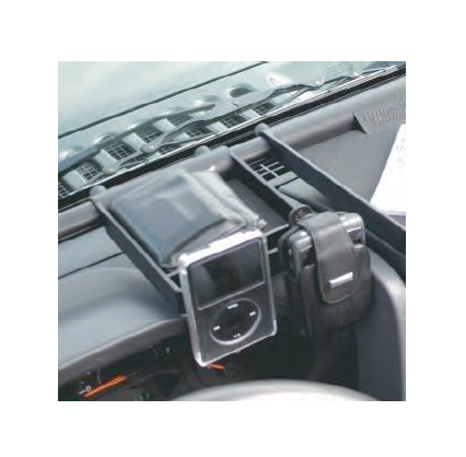
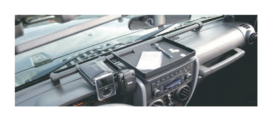
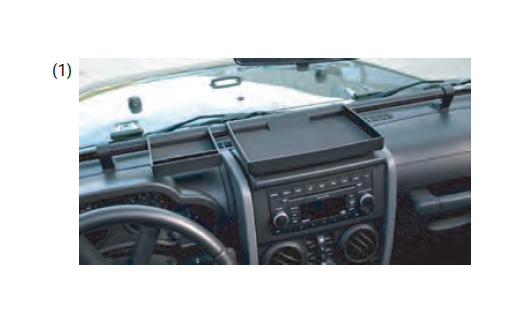
Your Rugged Ridge™ Dash Organizer is intended as supplemental storage for the off-road communication, navigation gear and accessories you need close at hand. As illustrated below, trays and accessories securely mount to an aluminum bar attached via supplied brackets to existing Jeep® dash mounts. No drilling is required. Review parts list and understand all instructions and warnings prior to beginning installation.
WARNING ! Reduce risk of serious injury in event of accident. Area above passenger side airbag must be kept clear in order for airbag to properly deploy. Accessories or trays cannot be mounted in this area. Do Not Remove tray stop bar. For on-road use, remove any accessories that may dislodge or pose impact risk in event of accident.
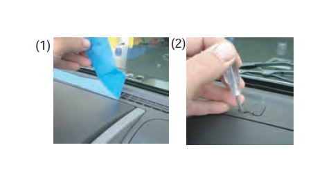
1. Place a strip of tape over the dash vent holes as shown. This will help to keep hardware from falling down behind the dash if dropped.
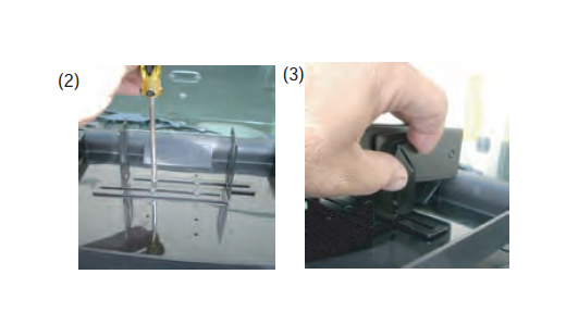
2. Using a small flat head screw driver carefully remove the two plastic caps located on either side of the dash.
3. Starting with the driver's side, place (1) M6 dash stand-off into dash opening and hand thread onto dash mounting stud located under plastic cap. Tighten dash stand-off with 15mm socket. Repeat on passenger side.
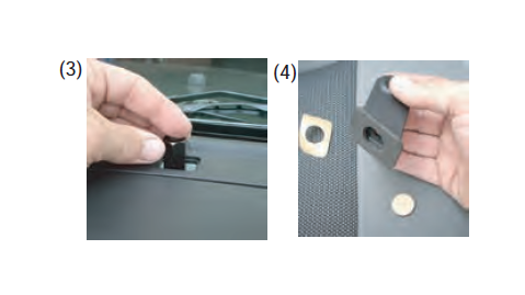
4. Apply foam foot pads to the bottom of both dash end caps. Place drivers side end cap over dash stand-off and hand thread (1) M6 hex head Bolt and (1) M6 flat washer through dash mount and into dash stand-off. Center mounting bracket and tighten hex head bolt using a 10mm wrench.
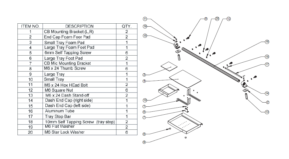
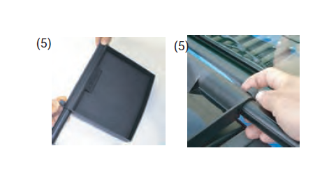
5. Place (4) M6 square nuts inside the back of aluminum tube. Slide the large tray over tube and attach to the square nuts with (2) M6 star lock washers and (2) M6 thumb screws. Repeat for the small tray and snug thumb screws down.
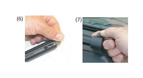
6. With trays installed, place (1) M6 square nut into the end of the aluminum tube. Slide tube assembly into the drivers side (left side) end cap and attach using (1) M6 star lock washer and (1) M6 thumb screws. snug thumb screw but do not tighten at this time.
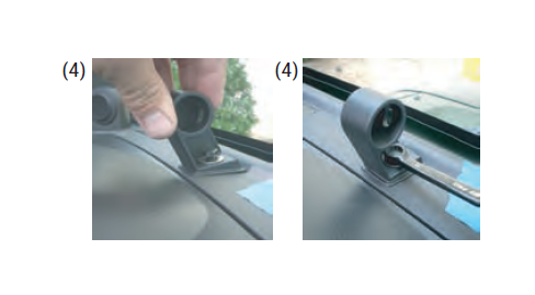
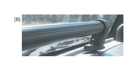
7. Place (1) M6 square nut inside the back of the aluminum tube on the passengers side. Place the (right side) dash end cap onto the end of the aluminum tube and secure using (1) M6 star lock washer and (1) M6 thumb screw.
8. Slide passenger (right side) end cap and tube onto dash stand-off (see step #3). Insert (1) M6 hex head bolt and (1) M6 flat washer through the dash end cap and tighten as far as possible by hand. When snug use 10mm wrench to complete installation.
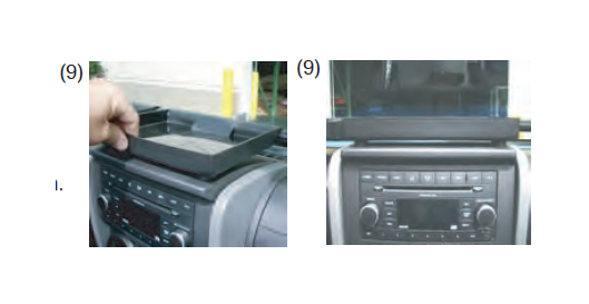
9. Slide the large tray to the center of the dash. Rotate tray until rubber pads are firmly resting on the top of dash. Tighten thumb screws. Slide small tray into position between the instrument display and Radio housing as shown. Rotate tray so that it is level with the large tray and tighten thumb screw.
WARNING! : Avoid risk of increased accident injuries by altering airbag deployment. DO NOT position tray or mount accessories over passenger-side airbag panel.
10. With trays centered tighten left and right dash end cap thumb screws. PLEASE NOTE: Adjustments can be made to the trays or the aluminum bar by loosening the thumb screws and rotating. When desired position is obtained retighten.
CB Mounting Instructions - (Optional)
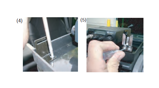
1. To mount CB remove rubber pad from center tray. Using the pre-drilled locating holes install the left and right CB mounting brackets using (4) 6mm self tapping screws as shown. DO NOT TIGHTEN. (3) mounting positions have been provided for different CB sizes.
2. Place CB between the brackets. Adjust so the brackets are resting against CB. tighten self tapping screws. Large rubber pad can be cut to fit CB brackets at this time.
3. Secure CB to brackets and adjust height as needed. Wire CB per manufactures instructions. For routing wiring, holes may be drilled in supplied recessed areas on bottom of tray.
4. Two sets of holes have been supplied for the CB mic mounting bracket. The mic can be mounted either on the left front or right front of the large tray. Attach mic mount with (2) 6mm self tapping screws as shown.
5. Attach mic holding bracket (not supplied) to CB mic mounting bracket.
* If desired other electronic components, such as GPS navigation unit, Cell Phone, or MP3 player, can be located on the large tray. The smooth tray surface will allow suction cup mounting brackets to be used.
* The small tray allows for any type of clip holder to be attached to the front of the tray. Slide clip holders onto tray as shown. Adjust tray if needed (see step #10).
* After installation double check all mounting hardware to insure that all components are secured tightly. Note: Always retighten thumb screws after moving or adjusting tube or trays.