 FREE 1 to 3-Day Delivery on Orders $149+ Details

How to Install Rugged Ridge 4" Lift Kit on your 1997-2006 Wrangler
Shop Parts in this Guide
- Rugged Ridge 4-Inch Suspension Lift Kit (97-02 Jeep Wrangler TJ)
- Rugged Ridge 2-Inch Suspension Lift Kit with ORV Shocks (03-06 Jeep Wrangler TJ)
- Rugged Ridge 2-Inch Suspension Lift Kit with ORV Shocks (97-02 Jeep Wrangler TJ)
- Rugged Ridge 4-Inch Suspension Lift Kit with ORV Shocks (97-02 Jeep Wrangler TJ)
A Few Words About Safety:
Your safety and the safety of other motorists is very important. As the owner of a modified suspension vehicle you are the person choosing the combination of suspension, wheels, tires and drive train that best fit your intended use. Likewise, you are the person responsible for the safety and legality of the vehicle you modify. In modifying your vehicle’s suspension, balance your off-road capabilities against how the vehicle may actually be used off-road and on-road.
It is not practical or possible to warn about all hazards associated with modifying your suspension for improved off road capabilities. To help you make informed decisions about safety, we have provided certain information in the form of “Notices” and “Warnings”. This information alerts you to potential hazards that could hurt you or others.
Notice: This is a caution against anything which may cause damage to the vehicle or its equipment if the caution is ignored. The Notice includes information about how you can avoid or reduce those risks.
Warning: This is a signal telling you that you CAN be KILLED or SERIOUSLY HURT if you don’t follow the Warning. The Warning includes information about what you must or must not do in order to reduce the risk of injury to yourself and others.
Pre-Installation Notes:
Notice: This kit should only be installed by a professional mechanic or individual with significant automotive experience.
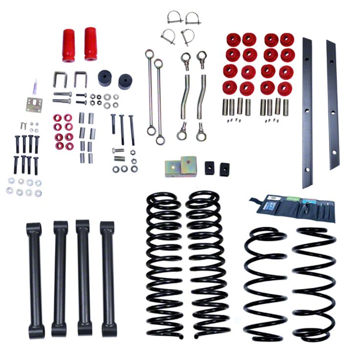
• Refer to parts list and inventory your kit to insure all parts and hardware pieces are available before beginning installation. Contact your independent dealer immediately if parts are missing.
• Installed lift will vary depending on vehicle options and configuration. As a reference and important guide should technical assistance be required, establish base ride-height measurements before beginning installation. Park vehicle on hard, level surface. Carefully measure the four corners of the vehicle (front and rear –both sides) from the ground up to the center of the fender opening above the axle. Record below and save.
Driver Side Front: __________________Passenger Side Front:____________________
Driver Side Rear: __________________Passenger Side Rear:____________________
FRONT:
1. Secure and properly block the tires of vehicle on a level concrete or asphalt surface.
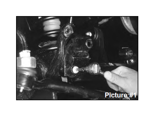
2. Jack up front of vehicle and install jack stands under frame behind the lower link rear brackets. Remove tires and front shocks. Now remove the track bar bolt on passenger side end only and lower track bar down (it may be necessary to pry bar loose). (See picture #1.)
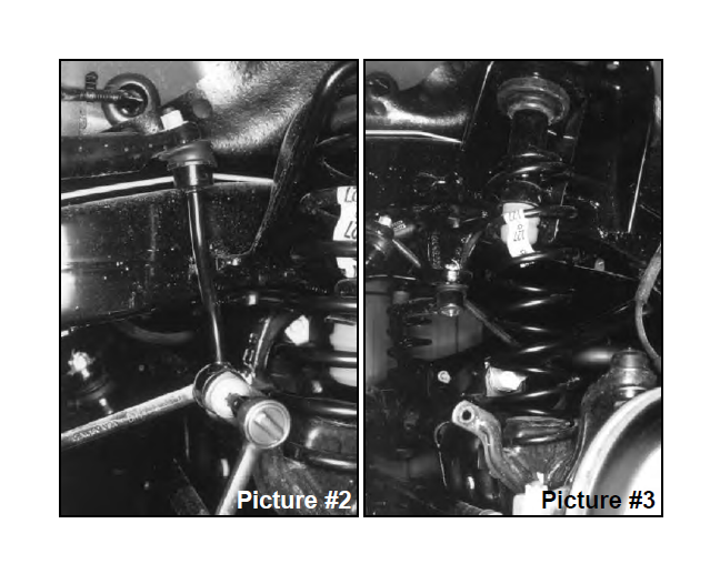
3. Remove drag link assembly from pitman arm and lower it down. (For 4" lifts, remove pitman arm also.) Now remove the sway bar end link's lower bolt at axle housing on both sides (see picture #2). Lower front axle down until coil springs become loose. Remove the bottom bolt and clip from left front coil spring (see picture #3).
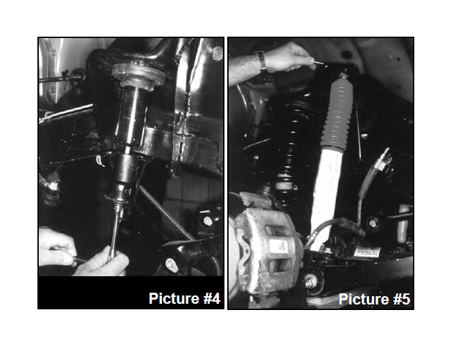
4. Now remove both coil springs. Remove upper bump stop (use channel lock pliers working bump stop back and forth). 2 1/2" Lifts: remove bolt from inside bump stop cup. Install bump stop spacer and original cup using 10mm x 23/4" long bolts furnished. Reinstall factory bump stop. (See picture #4.) 4" Lifts: Install new urethane bump stops.
5. Install new coil springs. Raise jack up so that enough load is applied to hold coil springs in place. Reinstall spring bolt and clip at bottom of left front coil.
6. Install new shocks. (See picture #5.) On 4" lifts, install new drop pitman arm at this time. Reinstall drag link to pitman arm and tighten (be sure to install cotter pin). Install tires and lower front to the ground.
7. 21/2" Lifts: Reattach track bar in original axle mount (it may be necessary to rotate steering wheel left or right to align bolt hole).
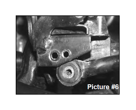
4" Lifts: Locate the front track bar mounting bracket on the axle, measure straight across to the right (inward) 3/4" and put a mark. Center punch and drill a 7/16" hole through both front and back plates, keeping the drill as straight and square to the bracket as possible (see picture #6). Reattach track bar (it may be necessary to rotate steering wheel left or right to align bolt hole).
8. 21/2" Lifts: Reinstall original sway bar end links on both sides and tighten (double disconnects available).
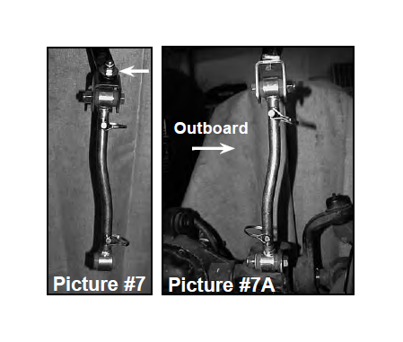
4" Lifts: NOTE: Sway bar end must be drilled or filed to allow clearance for the provided 7/16" x 1 1/2" bolt (see arrow in photo #7). The new end link mounting bracket should be mounted to the bottom of the sway bar with the bolt pointing up through the sway bar and the nut and 7/16 USS washer applied on top (see picture 7). Apply lithium grease to the polyurethane bushings. Insert them into the end link eyes along with the metal sleeve . The top 1/2" x 2 1/2" bolt connecting the bracket to the end link must be installed with the nut to the outside of the vehicle to provide adequate clearance to the frame. Install new double disconnect end links on the inboard side of the axle bracket, being sure that the offset is turned inward. (see picture #7A).
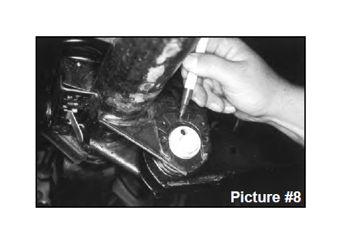
9. At the front lower link adjustment cams, mark (with an ink marker, or scribe a mark) the vertical line on the cam and the reinforcement bracket for reference so you can realign the marks after installation. (See picture #8.)
10.Install drive-in zirc fittings in each end of links by using a 1/4" socket over the fitting, tap with a hammer until fitting is completely tapped in.
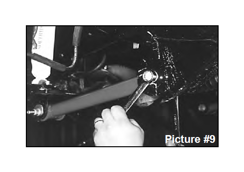
11. Install poly bushings and steel sleeves (2.645" long) in each end of links. Be sure to slightly grease them prior to the installation. Remove and replace the lower links with new Rugged Ridge extended links (one side at a time). See picture #9. Only start these bolts and nuts, do not tighten at this time. NOTE: so that the links may be greased while on the vehicle, install them with the zirc fittings positioned as follows: front eye of link has fitting pointing out the end, rear eye of link should have the fitting pointing down.
Once both links are installed, tighten each lower link being sure to realign the marks on the eccentric cams. Thoroughly grease all zirc fittings.
12.Place a jack under transfer case crossmember and remove the 4 screws that mount the transfer case pivot assembly from the body of vehicle (it will be necessary to roll floor mat back to gain access to bolts).
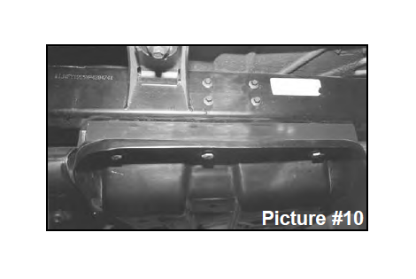
13.Remove the 3 bolts on each side of transfer case skid plate and lower down enough to install new square tube spacers between skid plate and frame. 1997-02 models use the flat socket head tapered bolts supplied. (2003-06 models will use the 12mm bolts and washers supplied). Also apply a few drops of supplied thread lock compound on bolt threads prior to installing. Tighten bolts to 75-80 ft.lbs. (Picture #10)
* On 2003-06 models, also remove the 2 engine skid plate bolts. Install the small square tube spacers at the mounting points on the frame rails, along with the 12mm bolts supplied. 2.5” kits will use the 1” square tube spacers. 4” kits will use the 1.5” spacer.
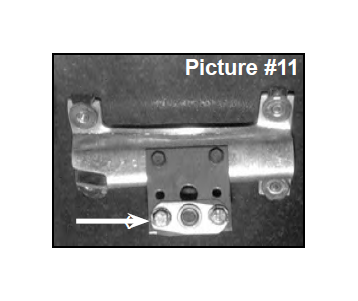
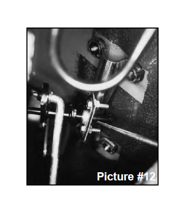
14.Install the new transfer case linkage pivot drop bracket to stock pivot bracket using stock screws. Using the two 1/4 x 1" bolts with a flat washer and self-locking nut, bolt the ball swivel bracket (arrow in picture #11) to new drop bracket (bracket now has 2 sets of holes: bottom holes for 4" lift as shown, or next to bottom for 21/2" lift). Placing pivot bracket back in location, start end of rod through ball swivel. Now bolt bracket back into location with original hardware (picture #12).
REAR:
1. Place a floor jack under rear axle and raise vehicle. Place jack stands under the frame ahead of lower link bracket to support vehicle and remove the rear tires and shock absorbers.
2. Remove rear track bar and sway bar end link bolts at axle housing. Lower rear axle down to remove coil springs.
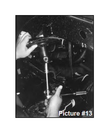
3. After removing both coil springs, remove the bump stops (it may help to use channel lock pliers working bump stop back and forth). Remove 10mm bolt from inside bump stop cup. Install bump stop spacer and original cup using furnished 10mm bolts Reinstall factory bump stop. (See picture #13.)
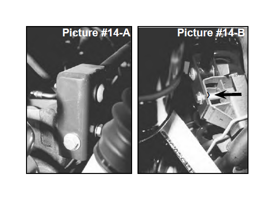
4. Referring to pictures 14 A & B, place new rear track bar relocation bracket in position and place track bar in new bracket (do not start its bolt). Start the new 12mm x70mm (23/4" long) bolt through the original lower track bar location using the supplied spacer sleeve with a self-locking nut. Tighten bolt to hold bracket in place.
Now drill a 1/2" hole through the hole in end of new bracket. Remove the 12mm x 70mm bolt, installed before drilling, and install a 1/2 x 11/2" bolt, with a washer on each side, through the new drilled hole, and then tighten with self-locking nut. Reinstall the new 12mm x70mm (23/4" long) bolt through the original track bar location using the supplied spacer sleeve ( see arrow in photo #14-B) with a selflocking nut and tighten. Still do not bolt up the track bar yet (must wait till on the ground).
5. Install new coil springs. Raise jack up so that enough load is applied to hold coil springs in place.
6. Install drive-in zirc fittings in each end of links by using a 1/4" socket over the fitting, tap with a hammer until fitting is completely tapped in. Install poly bushings and steel sleeves (2.645" long) in each end of links. Be sure to slightly grease them prior to installation.
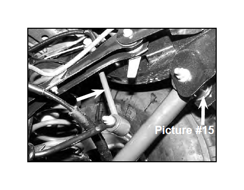
7. Remove and replace the lower links with new Rugged Ridge extended links (one side at a time). Only start these bolts, do not tighten at this time. NOTE: so that the links may be greased while on the vehicle, install the rear lower links with the zirc fittings positioned as follows: rear eye of link has fitting pointing out the end, front eye of link should have the fitting pointing down. (See picture #15, Black arrow.)
8. Attach track bar into new relocation bracket on axle then into the original upper location on passenger side frame (use original bolts, but do not tighten bolts at this time).
9. 21/2" Lifts: Reattach sway bar links to axle housing and skip to step 10, unless purchased extended rear sway bar end links.
4" Lifts: Assemble the rear extended sway bar links by applying grease to the polyurethane bushings and inserting them into each eye along with a sleeve . Install using original bolts. (See picture #15, White arrow.)
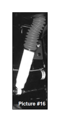
10.Install new shocks (see picture #16), install tires and lower rear to the ground. Now tighten the rear track bar bolts on each end and also the new bolt in relocation bracket. Thoroughly grease all zirc fittings in suspension links.
WARNING: On these Wrangler TJ Jeep models, only the shock absorbers limit the extended position of the front and rear suspension! The use of shocks other than those supplied in this system, may cause coil disengagement, adverse steering angles, brake hose failure, driveline component failure, and/or other related component failure! The use of other shocks will void your Rugged Ridge warranty!
FINAL NOTES:
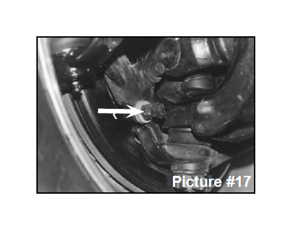
• Check clearance between inner side wall of tires and links. It may be necessary to adjust steering stops (by adding 2-3 washers on bolt) to eliminate interference. (See picture #17)
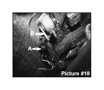
• Check the transfer case shifter to see if it will move to 4L. If not, the linkage will need adjusting as follows. Place the shifter in 4L, loosen adjustment bolt ("A" arrow in picture #18), and push the linkage ("B" arrow in picture #18) forward until it stops. Now retighten adjustment bolt. Check to be sure 4WD works properly.
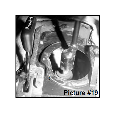
• On 5 speed models, engage the clutch and check the transmission shifter to see if it will go into 2nd gear. If not, the shifter housing on the floor will need trimming. Remove center console, pull back carpet, remove the screws holding shifter boot to floor and trim or grind floor board at arrow in picture #19 until sufficient clearance is obtained. Shift through each gear to check clearance at this time. Now reinstall boot, carpet and console.
• Driveline vibrations can be caused from the removal or addition of the hardtop which changes the rear vehicle weight, and the rear height, which affects the rear drive shaft pinion angle.
Post Installation Checks/Alignment:
• After installation is complete, double check that all nuts and bolts are tight. (Do not retighten nuts and bolts where Loctite was used.) Check to ensure there is adequate clearance between all rotating, mobile and fixed members.
• Rotate driveshafts and check for interference at differential yoke and cardan joint. If necessary, lightly dress casting(s) and/or U-joint tabs in order to eliminate binding.
• Check clearance between inner side wall of tires and links. It may be necessary to adjust steering stops.
Notice: Vehicles with 5" or more in lift, in some applications a replacement rear driveshaft may be required, Please contact Omix-Ada for more information.
Notice: Adjust drag link so that steering wheel remains centered and wheel sweep from side to side remains equal. Failure to do so may cause computer errors, odd handling characteristics and poor performance. Have a qualified alignment center check and realign to factory specifications.
Notice: With vehicle securely elevated, carefully inspect and adjust to assure adequate clearance between tires (inner side wall), body and suspension components throughout range of steering and suspension travel. Additionally, carefully inspect and adjust to maintain clearance between suspension components, wiring harnesses, exhaust, brake and fuel lines, fuel tank, floorboards and body panels. Complete by properly torquing all fasteners.
Notice: With vehicle now on floor, again check clearances, cycle steering lock to lock and test proper brake operation. Raised vehicle height requires realigning headlights. Consult your state’s lighting regulations. Wheels must be realigned by qualified service center to factory specifications.
Notice: Re-torque fasteners after 500 miles. Thereafter, regularly inspect and re-torque as needed. Follow vehicle manufacturer’s recommended maintenance procedures and routinely inspect your vehicle components for unusual wear or off-road damage.
Warning: Avoid compromising vehicle handling and safety (including roll over risk) by NOT adding, combining or fabricating additional lift devices (ex. body lifts) with this product. Also be aware that most states have restrictions on height modifications for vehicles used on-road. Consult your vehicle owners manual, the instructions and warnings accompanying this product and state law before undertaking these modifications or using your modified suspension vehicle on-road. A summary of current regulations affecting modified suspension vehicles is available from www.SEMA.org.
