 FREE 1 to 3-Day Delivery on Orders $149+ Details

How to Install Rugged Ridge 4-5" Lift Kit w/Shocks on your 2007-2013 Wrangler

Shop Parts in this Guide
Congratulations on your purchase of a Rugged Ridge™ suspension kit. To fully enjoy and understand this product we ask that you take a few moments to read through these instructions. Before beginning the installation, read these instructions and the enclosed driver’s “WARNING NOTICE” thoroughly and completely. Also affix the “WARNING” decal in passenger compartment in clear view of all occupants. If any of these items are missing from this instruction packet, do not proceed with installation, but call Omix-Ada to obtain needed items. If you have any questions or reservations about installing this lift kit, call Omix-Ada at 770-614-6101 for Technical Assistance or Customer Service departments.
A Few Words About Safety:
Your safety and the safety of other motorists is very important. As the owner of a modified suspension vehicle you are the person choosing the combination of suspension, wheels, tires and drive train that best fit your intended use. Likewise, you are the person responsible for the safety and legality of the vehicle you modify. In modifying your vehicle’s suspension, balance your off-road capabilities against how the vehicle may actually be used off-road and on-road.
It is not practical or possible to warn about all hazards associated with modifying your suspension for improved off road capabilities. To help you make informed decisions about safety, we have provided certain information in the form of “Notices” and “Warnings”. This information alerts you to potential hazards that could hurt you or others.
Notice: This is a caution against anything which may cause damage to the vehicle or its equipment if the caution is ignored. The Notice includes information about how you can avoid or reduce those risks.
Warning: This is a signal telling you that you CAN be KILLED or SERIOUSLY HURT if you don’t follow the Warning. The Warning includes information about what you must or must not do in order to reduce the risk of injury to yourself and others.
The following Warning label is included with your Rugged Ridge™ suspension kit and should be placed on the vehicle visor or other conspicuous location after installation:
Pre-Installation Notes:
Notice: This kit should only be installed by a professional mechanic or individual with significant automotive experience.
• Refer to parts list and inventory your kit to insure all parts and hardware pieces are available before beginning installation. Contact your independent dealer immediately if parts are missing.
• Installed lift will vary depending on vehicle options and configuration. As a reference and important guide should technical assistance be required, establish base ride-height measurements before beginning installation. Park vehicle on hard, level surface. Carefully measure the four corners of the vehicle (front and rear –both sides) from the ground up to the center of the fender opening above the axle. Record below and save.
Driver Side Front: _________________ Passenger Side Front:____________________
Driver Side Rear: _________________ Passenger Side Rear:____________________
Front Installation:
1. Park the vehicle on flat, level ground and set emergency
brake.
2. Raise the front of the vehicle and support frame rails using jack stands.
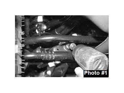
3. Disconnect the front sway bar end links using a 18mm socket. Disconnect front track bar using a 21mm socket. (See Photo #1)
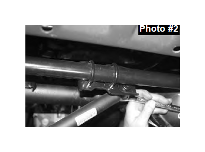
4. If installing Rugged Ridge Steering Stabilizer Part# 18475.03, Remove factory steering stabilizer using 18mm socket. (See Photo #2)
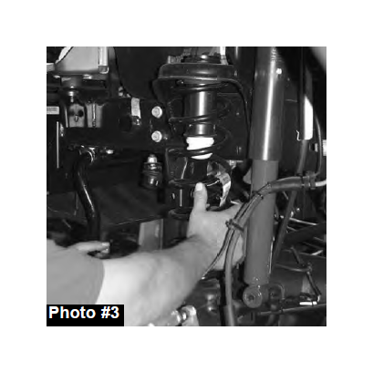
5. Disconnect front shocks using a 18mm socket. Remove front tires/wheels and remove front coils. (See Photo #3) Remove front Shocks.Mark driveshaft & yoke then remove.
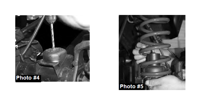
6. Locate new Rugged Ridge front bump stop. Place bump stop on the center of the bump stop pad located on the front axle. Mark and drill using a 25/64" drill bit. (See Photo #4).
7. Place bump stop in coil spring, and install coil spring. Attach bump stop to axle using the 3/8 X 4" button head bolts with one washer under the nut. (See Photo #5)
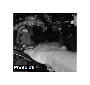
8. Locate the factory front track bar mount. Place the new Rugged Ridge relocation bracket inside the factory mount. Drill out the outer factory holes all the way through the rearward plate using a 7/16" drill bit. (See Photo #6) NOTE: It is recommended at this time to put a re-enforced weld on the factory bracket. Attach the bracket at the outer two locations using the 7/16 x 2 1/2" fine thread bolts, washers and nuts. Attach bracket at the factory location using the factory bolt. Let the weight of the frame down on to the new coils. Attach track bar to new bracket using the 14x80mm bolt, washers and nut.
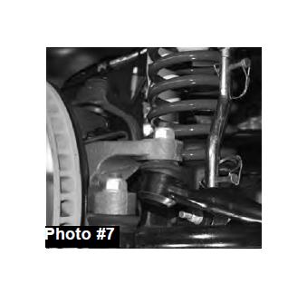
9. Re-Attach front drive shaft. Assemble new Sway bar end links using the 5/8" Hourglass bushings and steel sleeves. Attach eyes using the 1/4" snap pins. Attach end link to the axle using the factory hardware. (See Photo #7) Attach the lower portion of the sway bar using the 1/2 x 2 1/2" button head bolt. Use one large USS washer under the nut. Re-Attach front Drive Shaft.
If installing Rugged Ridge Steering Stabilizer, install at this time. (See
Photo Below).
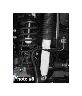
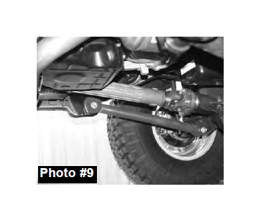
10. Install new Front shocks using hardware supplied. (See Photo #8). Locate new Lower front control arms. Install bushings and sleeves. Install 3/16" Tap in grease fittings into each end of the control arm. Note: The rear of the control arms have 2 locations for grease fittings. Therefore there is not a left or right control arm. When installed, one grease fitting will be accessible from the bottom. Install arms so that off set bend is toward the inside of the vehicle. Install using factory hardware. (See Photo #9)
11. Install tires and wheels. Lower vehicle to the ground.
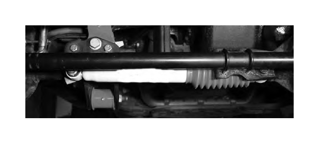
Note: Most models come equipped with a front transmission cross member. This cross member has 3 attachment points. One at each frame rail and one at the rear cross member. It will be necessary to lower this cross member using the supplied 1" spacers for driveline clearance. Install spacers using the 12 x 65 mm bolts supplied.
Rear Installation:
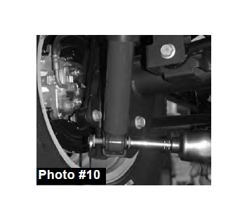
11. Raise rear end and properly support frame rails using jack stands. Remove rear shocks using 16mm socket. (See Photo #10)
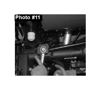
12. Disconnect rear track bar bracket from the axle using 21mm socket. (See Photo #11). Disconnect rear sway bar end links using 18mm socket.
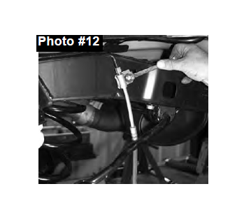
13. Disconnect ABS line from frame and disconnect brake line from frame. (See Photo #12) Lower axle down and remove factory rear coils.
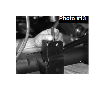
14. Place rear Track Bar relocation bracket over factory bracket on the axle. With bracket seated flush, mark and drill the new center mounting holes using a 15/32" drill bit. (See Photo 13)
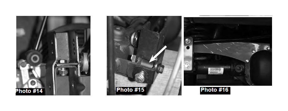
15. Install the supplied 7/16 x 1" fine thread bolt and fine thread nyloc nut. Use one 7/16" washer under the nut. (See Photo #14). Tighten nut at this time.
16. It will be necessary to drill through the driver side bottom of the OEM bracket and through the bracket. Drill using a 17/32" drill bit. Once drilled, install the supplied 1/2" x 1 1/4" fine thread bolt and nyloc nut. Use one washer under the bolt. Install the 9/16 x 3 1/2" bolt, washers and nut at the bottom location being sure to use the supplied crush sleeve. (See Arrow in Photo #15) Tighten all track bar bracket hardware at this time.
17. Install new rear coils. Be sure to re-use the upper OE Rubber isolator pad.
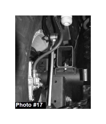
18. Attach new rear bump stops to the factory location on the axle using the 5/16 x 1" fine thread bolts, washers and nuts supplied. (See Photo #17) Be sure to install the bump stop so that the angled end is towards the rear.
19. Let weight on coil springs. Install new sway bar end links using the supplied 5/8" hourglass bushings and steel sleeves. Attach using the 1/2 x 2 1/2 button head bolts and nuts. If using a factory wheel the upper endlink bolt will need to be put in from the outside in for wheel clearance. One large USS washer will be used under the head of each bolt with the smaller SAE washer under the nut. (See Photo #17)
20. Install new track bar bracket brace at axle with supplied diff cover bolts (See Photo #16).Attach track bar to new bracket using 9/16 x 3" fine thread bolt, washer and nut. One washer will be used under the head of the bolt. 4" Kits will use the upper mounting hole in the new bracket. Be sure to install the bolt from the front side of the vehicle toward rear of the vehicle.Note: It is recommended to put a re-enforce weld on the factory track bar bracket at this time.
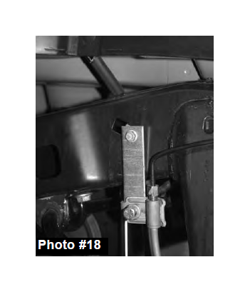
21. There are two brake line extension brackets supplied. The flat is for passenger side while the offset bracket is for the driver side. Attach the supplied brackets to the frame using the factory hardware. Attach brakeline to new bracket using the 5/16 x 1" fine thread bolt, washers and nut. (See Photo #18).
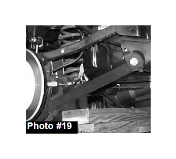
22. Remove lower control arms (one at a time). Install bushing sleeves and grease fittings into new lower control arms. Install new control arms so that grease fittings are pointed down. (See Photo #19)
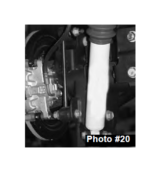
23. Install new rear shocks. (See Photo #20)
24. Install tires/wheels and lower vehicle to the ground
Post Installation Checks/Alignment:
• After installation is complete, double check that all nuts and bolts are tight. (Do not retighten nuts and bolts where Loctite was used.) Check to ensure there is adequate clearance between all rotating, mobile and fixed members.
• Rotate driveshafts and check for interference at differential yoke and cardan joint. If necessary, lightly dress casting(s) and/or U-joint tabs in order to eliminate binding.
• Check clearance between inner side wall of tires and links. It may be necessary to adjust steering stops.
Notice: Vehicles with 5" or more in lift, in some applications a replacement rear driveshaft may be required, Please contact Omix-Ada for more information.
Notice: Adjust drag link so that steering wheel remains centered and wheel sweep from side to side remains equal. Failure to do so may cause computer errors, odd handling characteristics and poor performance. Have a qualified alignment center check and realign to factory specifications.
Notice: With vehicle securely elevated, carefully inspect and adjust to assure adequate clearance between tires (inner side wall), body and suspension components throughout range of steering and suspension travel. Additionally, carefully inspect and adjust to maintain clearance between suspension components, wiring harnesses, exhaust, brake and fuel lines, fuel tank, floorboards and body panels. Complete by properly torquing all fasteners.
Notice: With vehicle now on floor, again check clearances, cycle steering lock to lock and test proper brake operation. Raised vehicle height requires realigning headlights. Consult your state’s lighting regulations. Wheels must be realigned by qualified service center to factory specifications.
Notice: Re-torque fasteners after 500 miles. Thereafter, regularly inspect and re-torque as needed. Follow vehicle manufacturer’s recommended maintenance procedures and routinely inspect your vehicle components for unusual wear or off-road damage.
Warning: Avoid compromising vehicle handling and safety (including roll over risk) by NOT adding, combining or fabricating additional lift devices (ex. body lifts) with this product. Also be aware that most states have restrictions on height modifications for vehicles used on-road. Consult your vehicle owners manual, the instructions and warnings accompanying this product and state law before undertaking these modifications or using your modified suspension vehicle on-road. A summary of current regulations affecting modified suspension vehicles is available from www.SEMA.org.
