 FREE 1 to 3-Day Delivery on Orders $149+ Details

How to Install Rubicon Express 5.5 in. Extreme Duty Lift Kit on your Jeep Wrangler
Installation Time
1 days
Tools Required
- 1” hole saw(s) for steel
- ½” drill motor & drill bits (including a high quality 5/8” bit)
- angle grinder
- Basic mechanical hand tools
- T-55 Torx head bit along with standard Torx head wrench set
- Floor jack & jack stands (2 Pair)
- Pitman arm puller
- welder Plasma cutter
- reciprocating saw w/metal cutting blades
- cutting wheels for angle or die grinder
INSTALLATION OVERVIEW
The installation process can be broken down into the following tasks:
1. Removal of factory lower control arm mounts on frame.
2. 3-piece frame crossmember.
3. Control arms.
4. Bump stops and coils.
5. Track bars, pitman arm and sway bar links.
6. Brake lines and shocks.
7. Final detailing and adjustments.
Step 1 - Removal of factory lower control arm mounts on frame.
A. First, support vehicle by frame (preferably on a lift) and work on a stable level surface. Support axles with jack stands and remove the following components; shocks, track bars, sway bar end links, coil springs, control arms, bump stops, brake hoses from axle end (it may be helpful to pinch-off hoses with vise grips to minimize fluid loss until new SS hoses are installed in step 6), and exhaust system behind the catalytic converter. NOTE: Coil springs can be removed without compressors if enough distance is generated between the axle and frame). If a lift is not being used, it may be easier to do this one side at a time on one axle at a time. CAUTION: If using coil spring compressors use extreme care as they will be holding a lot of potential energy and can release violently.
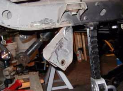
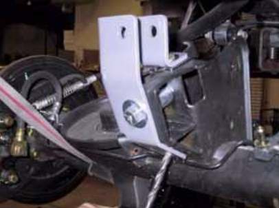
B. Cut off the (4) factory lower control arm mounts from the frame. Use extreme care as not to damage the frame, or cut into existing brake, fuel, or electrical lines.
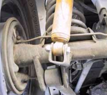
C. Grind rough areas smooth and repaint – refer to Photo 1 for typical bracket removal.
Step 2 - 3-piece frame crossmember
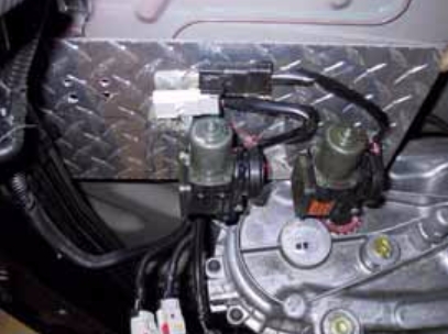
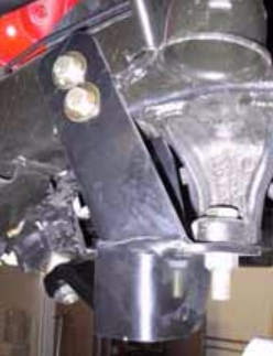
A. Support transmission and transfer case and remove stock crossmember. Note that the “Rubicon” model TJ’s will require that the installer fabricate a bracket to relocate the compressor (refer to Photo 2 for an example).
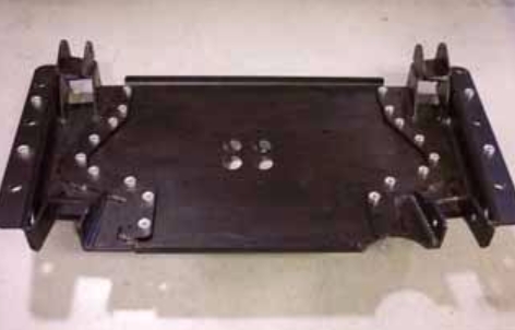
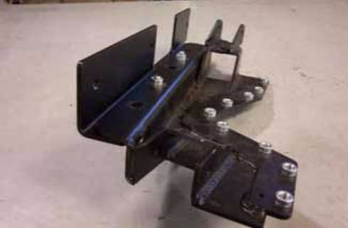
B. Assemble the right and left control arm mounts to the center section using only a few supplied flat head bolts for fitment purposes – refer to Photo 3 for orientation of parts. We will refer to this assembly from here on out as the “crossmember”.
C. Install crossmember using the six factory mounting bolts. Keep in mind that the two Pem nuts sticking up from each control arm mount will prevent the crossmember from fitting up flat against the frame bottom until the recess holes in step ‘F’ are made. Verify fitment to frame, transmission, transfer case and exhaust. This is the easiest time to make changes and install and remove the pan. Make note to adjust transfer case linkage and verify clearances.
D. Be sure to pull fuel lines, brake lines, etc. clear of drilling. With crossmember in place, mark with a center punch (through the Pem nuts) the location of the 2 recess holes required in the bottom of each frame rail. You will need to drill a 3/16” pilot hole at these four center punch marks.
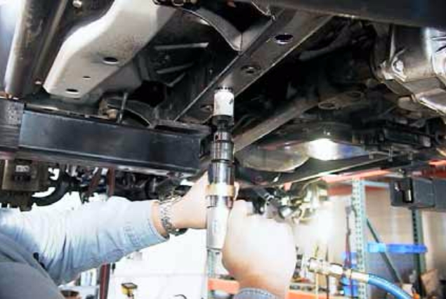
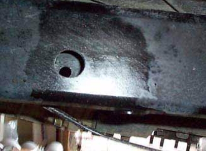
E. Remove pan and drill out the four pilot holes on center with a 1” hole saw – refer to Photo 4. Paint all bare metal for protection.
F. Attach right and left frame brace to crossmember, only finger tight, using two ½” bolts on each side into the Pem nuts – refer to Photo 5 for front view of right side assembly (less center section). Note large notch in brace is toward rear for clearance around body mount. Reinstall entire crossmember/frame brace assembly to frame.
G. With crossmember centered and frame braces tight against frame rails you are now ready to transfer mark the 3 holes on the side of both frame braces. Use a center punch or other method to accurately mark hole location to frame rail. After marking remove crossmember/frame brace assembly from frame once again.
H. Use a 3/16” drill bit to run a pilot hole through both sides of frame at all six hole locations. Use care to drill perpendicular to frame.
I. Use 1” hole saw to enlarge the six pilot holes only on outside surface of frame rail, and use ½” drill bit to enlarge the six pilot holes only on inside surface of frame rail opposite of 1” hole – refer to Photo 6.
J. Install six frame spacers into the holes you just drilled. We recommend welding the outside surface of spacer to the frame. If welding, chamfered edge goes to outside of frame for weld fillet. Grind flush when finished. If not welding, chamfer goes inward. Use ½” rod or bolt to align spacer with ½” hole in inside surface frame rail – refer to Photo 7. Repeat welding and grinding at the remaining five spacers and paint all bare metal to protect it.
K. You are now ready to permanently install pan. A total of 10 bolts will be used through bottom of frame braces and crossmember, and a total of 6 bolts will be used through side of frame braces and frame rails – refer to Photo 8. Install all remaining flat head bolts at center section and bolt the transmission mounting plate to crossmember and factory transmission mount.
Step 3 – Control Arms
A. FRONT - Adjust front lower control arms’ length to an initial setting of 37.5” from bolt center to bolt center. Final arm lengths seem to vary from around 37.5” to 38” depending on lift, axle squareness (see step C) and differential clearance to track bar. Install adjustable end of arm to front crossmember with supplied hardware (zerk on top). Position the arms so the welded on brackets for the front upper arms are on top and leaning toward each other.
B. Adjust front upper control arms’ length to an initial setting of 15-7/8” from bolt center to bolt center. Install front upper arms’ rubber bushing end into the welded on bracket of the lower arms with supplied hardware. The upper arms will be used to adjust final caster and pinion angle.
C. Attach front lower control arms to axle with factory hardware, and attach upper arms to axle with supplied hardware – refer to Photo 9. Checking distance from axle mount to front factory crossmember bolt should verify if axle is square, adjust if necessary.
D. REAR - Adjust rear lower control arms’ length to an initial setting of about 32-5/8” from bolt center to bolt center. this measurement will be 42.625”. Final arm lengths seem to vary from around 32-5/8” to 33.25” depending on lift, axle squareness (see step F), tire size, and gas tank clearance. Install adjustable end of arm to rear crossmember lower mounts with supplied hardware (zerk on bottom).
For LJ Unlimited: Adjust rear lower control arms’ length to an initial setting of about 42-5/8” from bolt center to bolt center. Final arm lengths seem to vary from around 42-5/8” to 43-1/4” depending on lift, axle squareness (see step F), tire size, and gas tank clearance. Install adjustable end of arm to rear crossmember lower mounts with supplied hardware (zerk on bottom).
E. Adjust rear upper control arms’ length to an initial setting of about 33-5/8” (for 5.5” kits with CV shafts) from bolt center to bolt center. For LJ Unlimited: This measurement needs to be 43-5/8”. It’s recommended that the 4.5” kits set this about 0.125” less to drop the pinion a bit. The 3.5” kits may need the arms a bit shorter yet. Install the arms to rear crossmember upper mounts with supplied hardware (zerk on top). The upper arms will be used to adjust final pinion angle.
F. Attach rear lower control arms to axle with factory hardware. Checking the distance from axle mount to front factory crossmember bolt should verify if axle is square, adjust if necessary. Attach upper arms to axle with supplied hardware (zerk on top) – refer to Photo 10. Upper arms can be mounted either direction.
Step 4 – Bump stops and coils
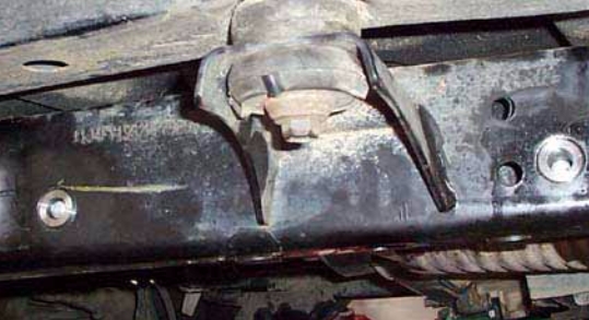
A. REAR BUMP STOPS - Remove the rubber insert from the rear bump stop. Remove the bump stop cup. Place the spacer between the bump stop cup and the tower using the supplied longer metric hardware. Reinstall stock rubber bump stop on 3.5” and 4.5” kits, or install RE1395 extended bump stops on 5.5” kits - refer to Photo 11.
B. REAR COILS - Install rear coils.
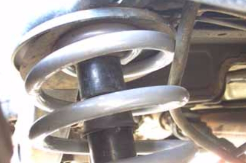
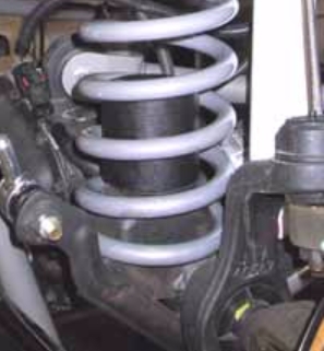
C. FRONT BUMP STOPS - Drill 5/16” hole in center of lower spring pads. Use self-tapping bolt through bump stop to cut threads in lower spring pad. Remove bolt and spacer, it will be installed with the spring.
D. FRONT COILS - Install the front coils with the bump stop inside of the coil – refer to Photo 12. Coil spring compressors may be useful. Once the spring is in place, put the bolt through the bump stop extension and thread the bolt into the lower spring pad (careful these strip easily). Be sure to rotate the coil to index the spring with lower coil cup, and reinstall coil spring clamp if removed earlier (not all vehicles have the spring clamps).
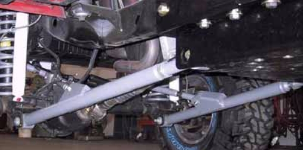
Step 5 – Track bars and sway bar links
A. REAR TRACK BAR BRACKET – Remove the plastic dust shield that covers the bolt securing the rear track bar to the mount on the axle housing and discard. Remove the Torx head bolt (T55) and disconnect axle end of track bar. Install track bar bracket using the supplied ½” bolt and spacer (the spacer goes in the location vacated by the track bar to prevent the bracket from deforming when the bolt is tightened - see photo 3 for similar installation). With the track bar bracket in place, drill two 5/16” holes in the axle mount where the plastic dust shield was previously located, one on top and one on angled surface. Install the 5/16” hardware in the holes drilled. If required, use supplied horseshoe shim to take up space between bracket and axle mount at top 5/16” bolt.
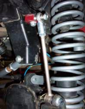
B. REAR TRACK BAR - Install the poly-bushing end of the new track bar at the frame. The bar should start out horizontal then turn down toward the axle bracket. Mount the Heim end of the track bar in the track bar bracket using the Torx bolt removed earlier – refer to Photo 13. Be sure the reducer bushing and two misalignment spacers are used (small end of spacers go up against Heim). It may be easier to do this later when vehicle is back on its wheels.
C. FRONT TRACK BAR/BRACKET – drill out factory bracket to 5/8” with a high quality bit and some cutting fluid (or similar). If using the RE1600 track bar skip to step ‘D’. If installing the RE1611 drop bracket for the RE1610 track bar, attach drop bracket with supplied 5/8” hardware to the factory one so the new bracket slides up each side of the frame rail. Drill ½” holes through the frame at the two holes in the new bracket being sure holes are perpendicular to the frame. Attach new bracket to the frame with supplied ½” hardware - Refer to Photo 14.
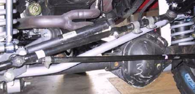
D. FRONT TRACK BAR - Attach new track bar to lower mounting bracket (axle side) using factory hardware. This will be the polybushing end of bar. Position bar so it starts out parallel with the axle (horizontal), then turns up toward the frame bracket. Before connecting bar to upper mount, center the vehicle over the axle by measuring the distance from front fender flare to tire on both driver and passenger sides of the vehicle, then adjusting vehicle until body is centered over the axle. The easiest way to accomplish this is when the vehicle is back on its wheels, have an assistant turn steering wheel left or right as necessary. Adjust spherical bearing end so that it will fit directly into the upper mount with the body centered. Tighten the jam nut to prevent the spherical bearing end from moving on the threads. Use supplied 10mm hardware to attach RE1610 to new bracket, or supplied 5/8” hardware to attach RE1600 bar to factory mount – refer to Photo 15 for typical installation.
E. If using the RE1611 dropped track bar bracket, install the drop pitman arm. Use a good pitman arm puller to remove old one
F. Install rear sway bar links just like the factory ones.
G. Install front sway bar quick disconnects per instructions supplied with disconnects – refer to Photo 16. The latest adapter bracket should mount down over the top of the sway bar and bolt should go up through sway bar, then through adapter bracket. The carriage bolt head should be toward the frame at top end of disconnects. Use the thick round spacer between the bottom disconnect and mount and put the nut on the tire side of the mount. Install disconnect tubes and snap pins.
Step 6 – Shocks and brake lines
A. Install longer front shocks. Some require bar pins to be installed through the bottom shock eyes (use light grease).
B. Position and weld on rear shock mounts – refer to Photo 17 for typical installation. The slot in the bracket is provided to place over control arm bracket, but different shocks or lengths may require different positions. Generally, the mounts end up in the neighborhood of 45 degrees, but it’s better to check that there is about 1” of shock travel remaining when the bump stops are touching their pads. Install longer rear shocks.
C. Fully remove front factory brake hoses and replace with the supplied stainless steel ones. Some require positioning the block and line vertically at the caliper. Watch line routing so they do not catch on anything during axle articulation. Use angle brackets and e-clips at the body end.
D. Fully remove rear brake line and install new one. Watch the routing so it does not catch on anything during axle articulation.
Step 7 - Final details and adjustments
A. Install wheels and lower vehicle.
B. Adjust the track bars to fit into the mounts with the axles as centered as possible (centering is not hyper critical).
C. Thoroughly bleed brake lines per factory manual and check for leaks and a firm pedal.
D. Torque all bolts to factory specs and double-check your work.
E. Test drive and note location of steering wheel and any driveline vibrations.
F. Adjust drag link to center steering wheel and align vehicle as soon as practical. Minimum factory caster and maximum factory toein seems to work well with these front ends (see Troubleshooting as well).
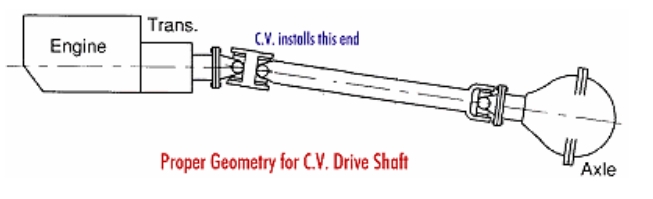
G. Adjust control arms if necessary. Note: Due to vehicle variations installer must verify proper driveline angles and axle placement to avoid tire rubbing or axle coming in contact with gas tank, steering linkage, or exhaust system. Shown below is picture showing proper pinion angle for a CV style drive shaft (see Troubleshooting as well).
H. Retighten all bolts after 50 miles and again after every off road excursion.
TROUBLESHOOTING
Rear driveline:
Acceleration vibration: Caused by the pinion being too high in relation to the transfer case output shaft. Adjust upper control arm to lower pinion accordingly.
Deceleration vibration: Caused by the pinion being too low in relation to the transfer case output shaft. Adjust upper control arm to raise pinion accordingly.
Slip yoke vibration: Caused by excessive angle on the transfer case slip yoke. This is not uncommon on lifted vehicles with some miles on them. For best performance, install a slip yoke eliminator (SYE) kit and CV drive shaft. Adjust pinion so it is about 2 degrees below parallel with CV drive shaft (see acceleration and deceleration vibration troubleshooting above).
High speed wobble:
It is a condition where front tires will shimmy after hitting a bump. Avoid bias ply tires and wheels with excessive offset. Check for worn or loose parts. In most cases a reduction of positive castor will eliminate this condition.
Bump steer: Caused by improper relationship of drag link and track bar. To correct, center axle again following the instructions supplied with the track bar. Next determine the neutral position of the steering wheel. Adjust the drag link to center the steering wheel. NOTE: A drop pitman arm should NOT be used on kits using the RE1600 front track bar in the factory mounts, as this will cause bump
