 FREE 1 to 3-Day Delivery on Orders $149+ Details

How to Install Rubicon Express 3.5" Super-Flex Lift Kit on your 1997-2006 Wrangler
Tools Required
- Basic mechanics' hand tools
- Jack stands and floor jack
- Spring compressors
- Drill motor and drill bits
Safety Warning:
Suspension systems or components that enhance the off-road performance of your
vehicle may cause it to handle differently, on and off-road, than it did from the
factory. Care must be taken to prevent loss of control or vehicle rollover during
sudden maneuvers. Failure to drive the vehicle safely may result in serious injury
or death to driver and passengers. We recommend you always wear your seatbelt,
drive safely and avoid quick turns and other sudden maneuvers. Constant
maintenance is required to keep your vehicle safe. Thoroughly inspect your vehicle
before and after every off-road use.
Installation Warning:
We recommend that certified technicians perform the installations of our products.
Attempts to install these products without knowledge or experience may jeopardize
the safety of the vehicle. These instructions only cover the installation of our
products and may not include factory procedures for disassembly and reassembly
of factory components. Read instructions from start to finish and be sure all parts
are present before disassembling the vehicle. Included instructions are guidelines
only for recommended procedures and in no way are meant to be definitive.
Installer is responsible to insure a safe and controllable vehicle after performing
modifications. Do not perform test drives on public roads with partially completed
installations. Always double and triple check your work before use.
Note:
It is necessary to remove the factory transmission skid plates from the
chassis after the suspension installation. Failure to do so will result in a
damaged front drive shaft.
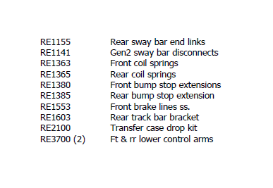
KIT CONTENTS:
PRE INSTALLATION NOTE:
Control arm bushings are pre-lubed during initial assembly at Rubicon Express. As general maintenance the control arm bushings should be lubed with a silicone base grease as needed. Silicone base grease can be purchased at your local auto parts store.
The Super-flex joints are also pre-lubed during initial assembly at Rubicon Express. As general maintenance the super-flex joints should be greased as needed and the outer spanner nut tightened on the joint. Any type of grease will work on the Super-flex joints. Spanner nut tools are available through Rubicon Express (RE3771 & RE3772) if needed for tightening of the joints.
INSTALLATION:
Note: It is recommended that CV rear driveshaft be used for best performance – see general vibration in troubleshooting before proceeding.
1. Raise vehicle and support with stands.
2. Remove wheels.
3. Remove front shocks.
4. Remove front sway bar end links.
5. Remove front spring retainer clamps.
6. Disconnect front track bar. Disconnecting steering at pitman arm makes axle droop out farther.
7. Remove front springs. Spring compressors may be helpful.
8. Support the front axle with jack stands.
9. Remove factory lower control arms.
10. Remove factory brake lines and replace with supplied lines. Some require positioning the block and line vertically at the caliper. Watch line routing, use angle brackets and e-clips.
11. Drill 5/16” hole in center of lower spring pads.
12. Use self-tapping bolt through bump stop extension spacer to cut threads in lower spring pad. Remove bolt and spacer, it will be installed with the spring.
13. If so equipped, use factory eccentric hardware at front axle lower arm mount. If not, use the supplied 9/16” bolt.
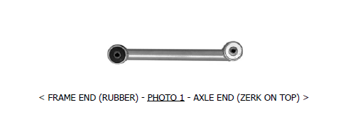
14. Install the lower control arms with the rubber bushing at the frame bracket. Use the factory hardware at the bushing end (don’t fully tighten until vehicle is back on the ground). The super-flex joint will be installed at the axle with the offset tube being mounted as low as possible (zerk on top – see Photo 1). Use supplied hardware for the Superflex end.
15. Install the front springs (RE1363) with the pig-tail at the top and the 2” bump stop extension inside of the coil. Coil spring compressors may be useful. Once the coil spring is in place, thread the bump stop bolt into the lower spring pad (refer to step #12). Rotate the coil to index the spring with lower coil cup.
16. Install the spring retainer clamp removed in step #5.
17. Install longer front shocks. Bar pins may need to be put through the bottom shock eyes (use light grease).
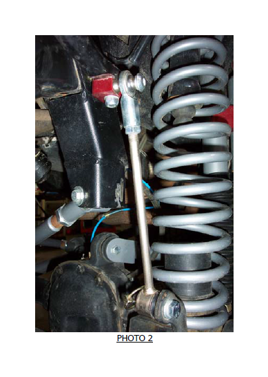
18. Install sway bar quick disconnects per instructions supplied with disconnects (see Photo 2 for typical installation).
19. Re-drill front track bar axle bracket over toward drivers side ¾”, center-to- center (or install optional adjustable front track bar). Reconnect track bar at new hole.
-REAR AXLE-
20. Remove the rear shocks.
21. Remove the rear sway bar end links.
22. Support the rear axle.
23. Disconnect rear track bar at axle.
24. Remove the factory lower control arms.
25. Remove the rear springs.
26. Remove the plastic dust shield that covers the bolt securing the rear track bar to the mount on the axle housing and discard.
27. Remove the Torx head bolt (t55) and disconnect axle end of track bar. If not done previously
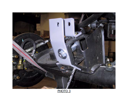
28. Install track bar bracket using the supplied ½” bolt and spacer (the spacer goes in the location vacated by the track bar to prevent the bracket from deforming when the bolt is tightened - see Photo 3 for similar installation).
29. With the track bar bracket in place, drill two 5/16” holes in the axle mount where the plastic dust shield was previously located, one on top and one on angled surface.
30. Install the 5/16” hardware in the holes drilled in step #29. If required, use supplied horseshoe shim to take up space between bracket and axle mount at top 5/16” bolt.
31. Install the track bar in the track bar bracket using the Torx bolt removed in step #27. It may be easier to do this later with weight on the vehicle.
32. Install the lower control arms with the rubber bushing at the unibody and super flex end at the axle. The offset tube should be mounted as low as possible (zerk on top - see Photo 1). Use the factory hardware at the uni-body and supplied bolt at the axle mount (don’t fully tighten until vehicle is back on the ground).
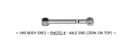
33. If installing optional upper control arms, set length 3/4” longer than stock for a CV drive shaft (1/4” if trying to use std shaft) as a good starting point (see general vibration in troubleshooting). Install the upper control arms using the factory hardware (don’t fully tighten until vehicle is back on the ground). Super flex end should be at axle with zerk on top (see Photo 4).
34. If installing optional cam bolts, install per instructions included with cam bolts (see General Vibration in Troubleshooting).
35. Remove the rubber insert from the rear bump stop. Remove the bump stop cup. Place the 1-1/2" bump stop extension between the bump stop cup and the frame using the supplied longer metric hardware.
36. Install springs. Spring compressors may be helpful.
37. Install replacement sway bar end links.
38. Install longer rear shocks.
39. If using, install transfer case drop kit by supporting one side of transfer case with floor jack. Remove hardware from one side of crossmember. Install spacers and new hardware. Tighten to 55 ft./lbs. Repeat on opposite side. NOTE: If used on a vehicle with a 6 speed manual transmission contact between the shifter and body may occur in 2nd, 4th, and Reverse. In this case it will be necessary to remove the shift boot to verify for clearance and possibly modify the body to allow a minimum of 1/8” clearance between the shifter and the body.
40. Install all tires.
41. Thoroughly bleed brake lines and check for leaks.
42. Double-check all nuts and bolts to factory torque specs.
43. Test drive and note location of steering wheel. Adjust drag link to center steering wheel.
44. Align vehicle as soon as practical. A good rule of thumb is minimum factory caster and maximum factory toe-in.
45. Recheck all bolts after 50 miles and again after every off-road excursion.
TROUBLESHOOTING
Rear driveline:
Acceleration vibration: Caused by the pinion being too high in relation to the transfer case output shaft. Adjust upper control arms or cam bolts (both optional) to lower pinion accordingly.
Deceleration vibration: Caused by the pinion being too low in relation to the transfer case output shaft. Adjust upper control arms or cam bolts (both optional) to raise pinion accordingly.
General vibration: Caused by excessive angle on the rear drive shaft. Very common on vehicles with 2” or more of lift. As a temporary fix, it may be possible to install the included transfer case drop kit and use a standard drive shaft. Optional cam bolts (RE1475) allow some adjustment of pinion angle and may help (see acceleration and deceleration vibration troubleshooting above). For best performance, install optional upper adjustable control arms (RE3783), a slip yoke eliminator (SYE) kit (or CV yoke on RUBICON model) and CV drive shaft. Adjust pinion so it is 2 degrees below parallel with CV drive shaft (see acceleration and deceleration vibration troubleshooting above). A transfer case drop kit can usually be omitted with a CV drive shaft. High speed
High speed wobble:
This is fairly common with y-type steering on lifted TJ's. It is a condition where front tires will shimmy after hitting a bump. Avoid bias ply tires and wheels with excessive offset. Check for worn or loose parts. In most cases a reduction of positive castor will eliminate this condition. A good rule of thumb is minimum factory caster and maximum factory toe in. Note that lift heights increased with coil spacers (or taller coils) may exhibit wobble that cannot be corrected with alignment.
Bump steer:
Caused by improper relationship of drag link and track bar. To correct, center axle again following the instructions supplied with the track bar. Next determine the neutral position of the steering wheel. Adjust the drag link to center the steering wheel.

