 FREE 1 to 3-Day Delivery on Orders $149+ Details

How to Install Rubicon Express 3.5" Super-Flex Lift Kit on your 2007-2013 Wrangler
Tools Required
- Basic mechanics hand tools. Optional floor jack
- jack stands
- wheel chocks for ground installation.
INSTALLATION OVERVIEW
The installation process can be broken down into the following tasks:
1. Installation of front control arms, track bar and bracket, coil springs and bump stops, shocks, and brake lines, Sway bar disconnects. RE7123B Page 2 of 6
2. Installation of rear control arms, track bar bracket, bump stops, coil springs, shocks, brake lines, and sway bar links
3. Final detailing and adjustments.
Step 1 – Front arm and component installation
A. With the vehicle and axle properly supported prepare the front end suspension component installation by removing the following items; shocks, sway bar links, and track bar. These items will not be reinstalled on the vehicle.
B. Remove the brake line attaching screw at the frame but keep the brake system sealed at this time. Unclip the abs wires from there attaching points for additional length. Lower the breather hose clip on the shock tower approximately 4”.
C. Lower the axle and remove both coil springs.
Front arm Installation
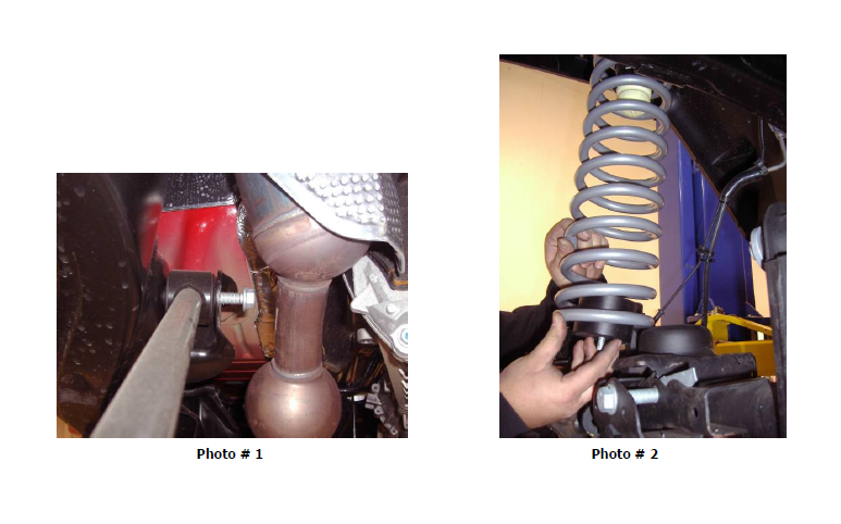
A. Remove the passenger’s side factory upper and lower control arms.
NOTE: It will be necessary to cut the upper control arm bolt off at the frame end to remove the passenger upper front arm. This is due to the bolt being installed from the inside out prior to the exhaust installation from the factory. Alternatively the head pipe assembly can be removed to pull the bolt out of the frame bracket. If choosing to unbolt the head pipe be sure to disconnect all O2 sensors before removal. (photo 1)
B. Set the upper arms to an initial setting of 18.75” center to center. With the supplied ½” bolt install the Super-Flex end of the arm into the frame pocket for the upper control arm and the fork of the arm over the bushing mount on the axle. Use the factory hardware thru the fork end of the arm.
C. Using the factory hardware install the lower arm into the frame pocket and the flex joint to the axle. The bend in the arm will be towards the center of the vehicle allowing for proper tire clearance. Both arms need to have the zerk fittings facing up to avoid
trail damage.
D. Repeat steps A – C on the driver’s side.
E. Loosely assemble all hardware on the control arms. When the vehicle is back on the ground under its own weight torque upper control arm bolts to 70ft/lbs and lower control arm bolts to 90 ft/lbs
NOTE: It will be necessary to re-adjust the upper arms during the final check to properly set the castor angle.
Front bump stops and coil springs
A. Place the front bump stop on the center of the lower spring mount on the axle tube. Insert a center punch thru the center hole in the bump stop and mark the hole to be drilled. Drill the marked hole to 5/16”, use the supplied self-tapping bolt to secure the
bump stop to the lower spring cup.
B. Raise the small diameter end of the coil into the upper spring bucket and over the lower spring cup and bump stop. Then raise the axle to seat the upper mount and rotate the coil to properly index in the lower mounts.
NOTE: If the axle cannot be dropped far enough from the frame due to brake line or ABS wire length to install the coil springs remove the bump stop and insert it into the coil. Then slide the coil over the stock axle mount and re-install the bump stop bolts.
(PHOTO # 2)
Front Track bar
A. Set the track bar at an initial setting of 32 7/8”. This measurement may vary due to the weight of your vehicles’ front end. We advise to pick a common point on both sides of the axle and then cross measure to the opposite side frame rail. By cross measuring, you are assuring the axle is centered under the vehicle.
B. Using the stock track bar bolt, install the bushing end into the axle mount. Attach the heim joint end of the track bar to the factory frame mount using the supplied misalignment spacers and the factory bolt. The bend on the track bar will be with the
elbow up to clear the front differential cover.
NOTE: It may be necessary to use a ratchet strap to pull the axle to the drivers side and install the track bar. Otherwise wait until the vehicle is on the ground under its own weight to install the track bar at the frame end. Moving the steering wheel back and
forth will assist in connection the track bar if the vehicle is on the ground.
Front brake lines, shocks, and sway bar links/disconnects
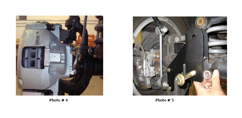
A. Remove and replace the front brake lines with the included stainless steel brake lines. The lines are left and right specific, when installed the 90 degree leader from the caliper should be leaning away from the tire. (photo 4, front shown)
B. Depending on what shocks have been purchased with the suspension system, it may be necessary to reuse the sleeves and bar pins from the stock shocks. If this is necessary be sure to lubricate the sleeves or bar pins during removal and most importantly during re-installation.
C. See supplied instruction sheet for the front sway bar link / disconnect information (RE1143). This kit contains all parts necessary to be used on a Jeep Rubicon model with factory electronic disconnect as well as X and Sahara Jeep models.
Step 2 – Rear arm and component installation
A. With the vehicle and axle properly supported prepare the rear end suspension component installation by removing the following items; shocks, sway bar links, and track bar at the frame only (loosen the track bar bolt at the axle). The shocks and sway bar links will not be reinstalled on the vehicle.
C. Remove the brake line attaching screw at the frame but keep the brake system sealed at this time. Unclip the abs wires from there attaching points on the axle brackets for additional length. Remove the two nuts holding the E-brake cables to the bottom of the body.
D. Lower the axle and remove both coil springs. The rubber isolators will come out with the coil and must be reinstalled with the new coil springs.
Rear track bar bracket and factory track bar (photo 5)
NOTE: With the installation of the rear track bar bracket you may notice that at ride height, the axle is not completely centered under the chassis; this is intentional. The reason for such offset at ride height is to allow for proper tire to frame, and/or control arm clearance. Centering the axle under the chassis at ride height may cause the tire to contact the frame and/or control arm which may result in tire damage or failure!
A. With the axle properly supported remove the driver’s side rear lower control arm from the frame and axle.
B. Place the new track bar bracket over the factory track bar mounting point on the axle while aligning the two 3/8” holes on the back side of the lower control arm bracket. Loosely install the two 3/8” bolts, washers, and nuts thru the lower control arm bracket and track bar bracket.
C. Install the 9/16x3.5” bolt thru the factory track bar location being sure to use the supplied spacer to keep the factory bracket from collapsing. Tighten the two 3/8” bolts to 35 ft/lbs then tighten the 9/16” bolt to 90 ft/lbs.
D. Using the supplied 9/16x3” install the factory track bar into the new bracket. Install the nut on the back side near the coil spring but do not tighten at this time.
Rear Arms
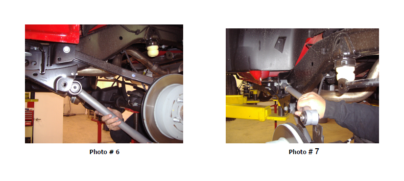
A. With the axle already supported and the driver’s rear lower arm already removed install the Rubicon Express Super-Flex control with the rubber bushing at the frame end and the Super-Flex Joint at the axle. Reuse all factory hardware for arm installation and make sure the zerk fitting is on top to avoid trail damage. (Photo 6)
B. Set the rear upper control arms to a base line setting of 17 5/8”. This measurement may vary depending on driveshaft angle and JK model. Install the arm with the Super-Flex joint at the frame and the rubber bushing at the axle. Reuse all factory bolts and nuts for attaching the upper arms. (Photo 7)
Note: It will be necessary to re-adjust the upper arms during the final check to properly set the pinion angle.
Rear bump pads, coil springs, and sway bar links
A. Install the two bump pads on top of the axle housing using the supplied 3/8” hardware.
B. Using the factory spring isolator place the rear coils up into the upper mount and over the lower mount. Raise the axle into place just enough to keep the coil spring from falling out.
C. Install the supplied links (RE1157). Install the drivers side link to the outside of the sway bar and lower axle mounting point. On the passengers side install the link on the outside of the sway bar link and lower axle mount.
Rear brake lines and shocks
A. Remove and replace the rear brake lines with the included stainless steel brake lines. The lines are left and right specific and when installed the 90 degree leader from the caliper should be leaning away from the tire. (photo 4, front shown)
B. Depending on what shocks have been purchased with the suspension kit it may be necessary to reuse the sleeves and bar pins from the stock shocks. If this is necessary be sure to lubricate the sleeves or bar pins during removal and most importantly during re-installation.
Step 6 - Final details and adjustments
A. Install wheels, verify all coils are properly seated shocks installed and lower the vehicle.
B. Check the front track bar for axle center, adjust as necessary.
C. Tighten all control arm and track bar rubber bushing hardware. Use factory specs where factory bolts are used.
D. Properly bleed brake lines per factory manual and check for leaks and a firm pedal.
E. Manually disable the factory ESP system before the first test drive. (Refer to owners manual for the disable procedure) Note the location of steering wheel while driving in a straight line and any driveline vibrations.
F. Adjust drag link to center the steering wheel. NOTE: Centering the steering wheel is highly critical for proper ESP function. Minimum factory caster and maximum factory toe-in is the recommended initial setting for alignment (see Troubleshooting as well).
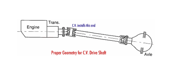
G. Adjust upper control arms if necessary for proper front castor angle and rear pinion angle. NOTE: Shown below is a diagram of
proper pinion angle for a CV style drive shaft (see Troubleshooting as well).
H. Retighten all bolts after 50 miles and again after every off road excursion.
I. After all adjustments have been made, Rubicon Express recommends that your local Jeep dealership “flash” the computer to adjust for proper tire size and ESP control settings.
TROUBLESHOOTING
Rear driveline:
Acceleration vibration: Caused by the pinion being too high in relation to the transfer case output shaft. Adjust upper control arm to lower pinion accordingly.
Deceleration vibration: Caused by the pinion being too low in relation to the transfer case output shaft. Adjust upper control arm to raise pinion accordingly.
High speed wobble:
It is a condition where front tires will shimmy after hitting a bump. Avoid bias ply tires and wheels with excessive offset. Check for worn or loose parts. In most cases a reduction of positive castor will eliminate this condition.
