FREE 1 to 3-Day Delivery on Orders $149+ Details

How to Install a Rubicon Express 3.5 inch Lift Kit on your Jeep Wrangler JK
Tools Required
- Basic mechanics hand tools. Optional floor jack, jack stands, wheel chocks for ground installation

Shop Parts in this Guide
Safety Warning:
Suspension systems or components that enhance the off-road performance of your vehicle may cause it to handle differently, on and off-road, than it did from the factory. Care must be taken to prevent loss of control or vehicle rollover during sudden maneuvers. Failure to drive the vehicle safely may result in serious injury or death to driver and passengers. We recommend you always wear your seat belt, drive safely and avoid quick turns and other sudden maneuvers. Constant maintenance is required to keep your vehicle safe. Thoroughly inspect your vehicle before and after every off-road use.
Installation Warning:
All procedures described in these instructions were performed while the vehicle was properly supported on a vehicle lift. Use caution when supporting the vehicle as removing and installing parts will change the vehicle center weight. Rubicon Express recommends that chassis support jacks are always used at the front and rear of the vehicle during the installation of a suspension system.
We recommend that certified technicians perform the installations of our products. Attempts to install these products without knowledge or experience may jeopardize the safety of the vehicle. These instructions only cover the installation of our products and may not include factory procedures for disassembly and reassembly of factory components. Read instructions from start to finish and be sure all parts are present before disassembling the vehicle. Included instructions are guidelines only for recommended procedures and in no way are meant to be definitive. Installer is responsible to insure a safe and controllable vehicle after performing modifications. Do not perform test drives on public roads with partially completed installations. Always double and triple check your work before use.
ESP WARNING NOTE: The new 2007 Jeep Wrangler JK is equipped an Electric Stability Program (ESP). This system is designed to help control the vehicle in times of uncertain traction conditions and roll stability. Due to the complex nature of this program Rubicon Express strongly suggest that after lifting the vehicle it is returned to the dealer for a computer “flash” to re address tire size and proper ESP control settings. Rubicon Express also recommends that you become familiar with the ESP controls and how the different level of settings can help you to keep better control of your vehicle.
WHEEL NOTICE: If using factory wheels it will be necessary to purchase 1.5” wheel spacers to provide proper clearance to suspension components. Otherwise aftermarket wheels with 4.5” back space measurement will be required.
KIT CONTENTS
RE1157 Rear Sway Bar End Links
RE1370 (2 Door)
RE1371 (4 Door) Front 3.5” Coil Springs
RE1375 (2 Door)
RE1376 (4 Door) Rear 3.5” Coil Springs
RE1380 2” Front lower bump stops
RE1387 Rear bump stop pad
RE1476 JK front lower cam bolt set
RE1477 JK rear upper cam bolt set
RE1507 JK front brake line relocation brackets
RE1508 JK rear brake line relocation brackets
RE1607 Rear Lower Track Bar Bracket
RE1673 Front Adjustable Track Bar
INSTALLATION OVERVIEW
The installation process can be broken down into the following tasks:
1. Installation of front coil springs, bump stops, track bar, front lower cam bolts, and brake line relocation brackets.
2. Installation of rear coil springs, bump stops, track bar bracket, brake line relocation brackets, sway bar links and rear upper cam bolts.
3. Final detailing and adjustments.
Step 1 – Front coil and component installation
A. With the vehicle and axle properly supported prepare the front end suspension component installation by removing the following items; shocks, sway bar links (from the axle end only), and track bar. Loosen but do not remove the lower control arm bolts at the axle, they will be replaced later with caster adjusting cam bolts. The factory shocks and track bar will not be reinstalled on the vehicle.
B. Remove the brake line attaching screw at the frame and let the lines hang loose until later in the install. DO NOT remove the brake lines or loosen the brake line fittings. Lower the breather hose clip on the shock tower approximately 3”.
C. Lower the axle and remove both coil springs.
D. Place the front bump stop on the center of the lower spring mount on the axle tube. Insert a center punch thru the center hole in the bump stop and mark the hole to be drilled. Drill the marked hole to 5/16”
E. With the lower bump stop placed inside the new front coil spring, raise the small diameter end of the coil into the upper spring bucket and over the lower spring cup and bump stop pad. Rotate the coil spring so the end of the coil properly sits in the factory pocket and install the supplied 3/8” self tapping bolt thru the bump stop and secure to the axle. (Photo #1)
F. Raise the axle towards the chassis and install the new shock absorbers. (Purchased separately)
Photo 1
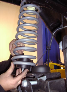
Photo 2
Front Track bar
A. Set the track bar at an initial setting of 32 7/8”. Loosely install the bushing end of the track bar into the axle mounting bracket reusing the factory bolt and nut.
B. Using the factory bolt and supplied misalignment sleeves install the rod end into the factory track bar mount at the frame. Do not fully tighten the track bar at this time, the axle center needs to be checked after completion of the entire system and the vehicle is on the ground. The bend on the track bar will be with the elbow up to clear the front differential cover.
NOTE: It may be necessary to use a ratchet strap to pull the axle to the drivers side and install the track bar. Otherwise wait until the vehicle is on the ground under its own weight to install the track bar at the frame end. Moving the steering wheel back and forth will assist in connection the track bar if the vehicle is on the ground.
Front lower cam bolt installation
A. One side at a time remove the factory bolt that attaches the lower control arm to the axle.
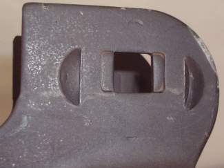
B. Locate the indented marks around the square hole in the bracket to be removed.
C. Using a punch, hammer, and a receiving cup such as a socket that fits between the mounts knock out the tabs to create elongated holes. If the tabs will not knock out with a couple hits of the punch, it will be necessary to use a burr type cutter to elongate the holes. (Photo 2) example, rear upper pictured
D. Install the cam bolt assemblies with one washer on each side of the bracket between the locating ears. Rotate the bolt into the center portion of the slot and tighten the nut so the bolt will not spin but not fully tight at this time.
Front brake line extension brackets and sway bar links
A. With the front brake lines previously unbolted from the side of the frame install the brake line extension brackets to the frame with the factory hardware. The tab end of the extension will locate in the frame rail as did the brake line.
B. Remove the clips that attach the ABS wire to the brake line.
C. Using the supplied ¼” hardware bolt the brake line tab to the lower hole of the extension bracket. (Photo #3)
NOTE: When lowering the brake line mounting point, use caution when pulling on the hard lines. It may be necessary to straighten some of the bends in the lines to get enough extension however excessive force or bending could weaken the hard brake line and potentially cause a leak in the system.
D. With the brake line secured in its new location safely re-route the ABS wires and secure to the brake line with plastic zip ties.
E. Remove the rear sway bar links from the axle and sway bar and re-install to the front axle and sway bar. New rear links are supplied.
Photo 3
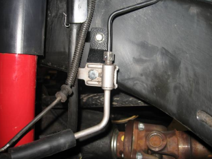
Photo 4
Step 2 – Rear coil and component installation
A. With the vehicle and axle properly supported prepare the rear end suspension component installation by removing the following items; shocks, sway bar links, and track bar at the axle end only (loosen the track bar bolt at the frame). The shocks and sway bar links will not be reinstalled on the vehicle.
B Remove the brake line attaching screw at the frame and let the lines hang loose until later in the install. Unclip the abs wires from the forward attaching point on the upper control arm brackets for additional length. It may also be helpful to remove the two nuts holding the E-brake cables to the bottom of the body to allow for more axle droop and easier removal and installation of the coil springs.
C. Lower the axle and remove both factory coil springs. The rubber isolators will come out with the coil and must be reinstalled with the new coil springs.
D. Install the new coil springs with isolators at the top and raise the axle just enough to keep the springs and isolators in place.
Rear Upper Cam bolt installation
A. One side at a time remove the factory bolt that attaches the upper control arm to the axle.
B. Locate the indented marks around the square hole in the bracket to be removed. (Photo 2)
C. Using a punch, hammer, and a receiving cup such as a socket that fits between the mounts knock out the tabs to create elongated holes. If the tabs will not knock out with a couple hits of the punch, it will be necessary to use a burr type cutter to elongate the holes.
D. Install the cam bolt assemblies with one washer on each side of the bracket between the locating ears. Rotate the bolt into the center portion of the slot and tighten the nut so the bolt will not spin but not fully tight at this time.
Rear bump pads, track bar bracket and factory track bar
A. Install the two bump stops on the axle with the supplied 3/8” bolts and lock nuts.
B. With the axle properly supported remove the driver’s side rear lower control arm from the axle this will allow for easier access when installing the track bar bracket.
C. Place the new track bar bracket over the factory track bar mounting point on the axle while aligning the two 3/8” holes on the back side of the lower control arm bracket. Loosely install the two 3/8” bolts, washers, and nuts thru the lower control arm bracket and track bar bracket.
D. Install the 9/16x3.5” bolt thru the factory track bar location being sure to use the supplied spacer to keep the factory bracket from collapsing. Tighten the two 3/8” bolts to 35 ft/lbs then tighten the 9/16” bolt to 90 ft/lbs.
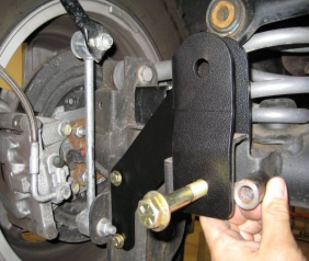
E. Using the supplied 9/16x3” install the factory track bar into the new bracket. Install the nut on the back side near the coil spring but do not tighten at this time. (Photo 4)
F. Reinstall the lower control arm to the axle mounting point and tighten the bolt.
Rear sway bar links, brake line extensions, and shocks
A. Install the supplied links (RE1157). Install the drivers side link to the outside of the sway bar and lower axle mounting point. (Photo 4) drivers side shown
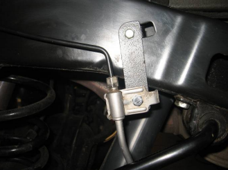
B. Install the supplied brake line extension brackets to the frame with the factory hardware. Use the supplied hardware to reattach the brake line bracket to the lowering bracket (photo 5)
C. Install new shock absorbers. (sold separately)
Photo 5
Step 6 - Final details and adjustments
A. Install wheels, verify all coils are properly seated shocks installed and lower the vehicle.
B. Check the front track bar for axle center, adjust as necessary.
C. Tighten all control arm and track bar rubber bushing hardware. Use factory specs where factory bolts are used.
D. If front castor angle or rear pinion angle need adjustment do so by loosening the cam bolt nuts and rotating each bolt in the direction needed to get the desired angle. Tighten the nut after adjustments are made.
E. Manually disable the factory ESP system before the first test drive. (Refer to owners manual for the disable procedure) Note the location of steering wheel while driving in a straight line and any driveline vibrations.
F. Adjust drag link to center the steering wheel. NOTE: Centering the steering wheel is highly critical for proper ESP function. Minimum factory caster and maximum factory toe-in is the recommended initial setting for alignment (see Troubleshooting as well).
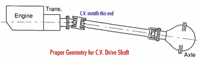
G. Adjust upper control arms if necessary for proper front castor angle and rear pinion angle. NOTE: Shown below is a diagram of proper pinion angle for a CV style drive shaft (see Troubleshooting as well).
H. Retighten all bolts after 50 miles and again after every off road excursion.
I. After all adjustments have been made, Rubicon Express recommends that your local Jeep dealership “flash” the computer to adjust for proper tire size and ESP control settings.
TROUBLESHOOTING
Rear driveline:
Acceleration vibration: Caused by the pinion being too high in relation to the transfer case output shaft. Adjust upper control arm to lower pinion accordingly.
Deceleration vibration: Caused by the pinion being too low in relation to the transfer case output shaft. Adjust upper control arm to raise pinion accordingly.
High speed wobble:
It is a condition where front tires will shimmy after hitting a bump. Avoid bias ply tires and wheels with excessive offset. Check for worn or loose parts. In most cases a reduction of positive castor will eliminate this condition.