FREE 1 to 3-Day Delivery on Orders $149+ Details

How to Install Rough Country Front Control Arm Geometry Correction Brackets on your Jeep Wrangler
Installation Time
2 hours
Tools Required
- Jack Stands
- Floor Jack
- Reciprocating Saw
- 18mm Socket / Wrench
- 19mm Socket / Wrench
- 21mm Socket / Wrench
- 22mm Socket / Wrench
PRODUCT USE INFORMATION
Rough Country makes no claims regarding lifting devices and excludes any and all implied claims. We will not be responsible for any product that is altered. If question exist we will be happy to answer any questions concerning the design, function, and correct use of our products by calling 1-800-222-7023.
IMPORTANT NOTE : Upon completing the install of this kit the draglink must be adjusted to center the steering wheel BEFORE the vehicle is driven. Failure to do so will cause a computer error, odd handling, and poor performance.
NOTICE TO DEALER AND VEHICLE OWNER
Any vehicle equipped with any Rough Country product should have a “Warning to Driver” decal installed on the inside of the windshield or on the vehicle’s dash. The decal should act as a constant reminder for whoever is operating the vehicle of its unique handling characteristics.
INSTALLING DEALER - it is your responsibility to install the warning decal and forward these installation instructions on to the vehicle owner for review. These instructions should be kept in the vehicle for its service life.
INSTALLATION INSTRUCTIONS
1. Chock the rear wheels.
2. Jack up the front of the vehicle and support with jack stands on the frame just rearward of the lower control arm mounts.
3. Place a jack under the axle and lightly support the weigh of the axle.
4. On 2012 models the heat shield on the passenger side upper arm will need to be removed. The heat shield will not be reused. Remove shield at this time.
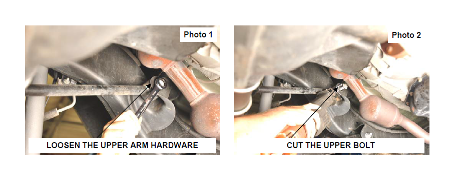
5. Loosen the upper control arm bolt on the frame and from the axle using a 18mm wrench. See Photo 1. Retain the axle hardware as it will be reused.
6. To remove the upper control arm the frame bolt must be cut. See Photo 2. Cut the bolt as shown.
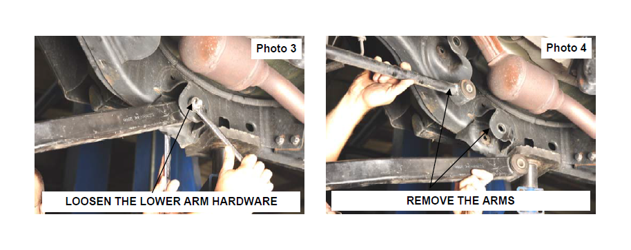
7. Loosen and remove the lower control arm hardware from the axle and frame using a 21mm wrench. Retain the factory hardware. See Photo 3.
8. Remove the upper and lower control arms from the vehicle. See Photo 4.
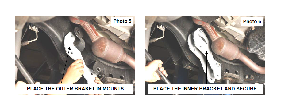
9. Place the outer frame bracket as shown on the frame mounts as shown in Photo 5.
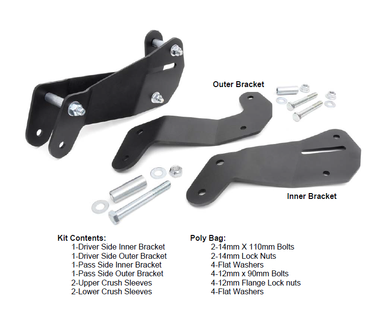
10. Install the inner frame bracket with the supplied crush sleeves and secure with the 14mm x 110mm bolt, washers and lock nut on the lower mount and the supplied 12mm x 90mm bolt, washers and flange lock nut on the upper mount. Do not tighten at this time. See Photo 6. The bracket with the slot is the inner bracket.
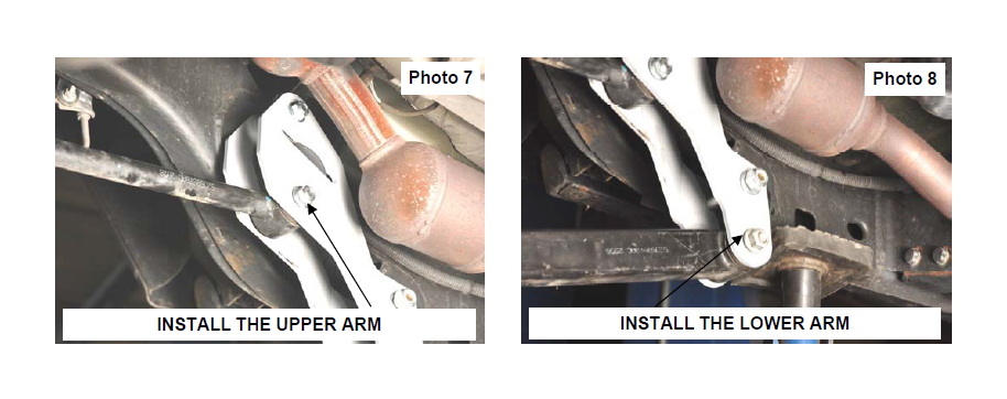
11. Install the upper control arms in the relocation brackets with the supplied 12mm x 90mm bolts, washers /nuts. See Photo 7.
12. Install the lower control arms in the relocation bracket using the factory hardware. See Photo 8.
13. Reinstall the tires and wheels.
14. Jack up the vehicle and remove the jack stands.
15. Lower the vehicle to the ground.
16. Tighten all hardware at this time.
17. Tighten the upper arm hardware using a 19mm socket / wrench.
18. Tighten the lower arm hardware using a 22mm socket / wrench.
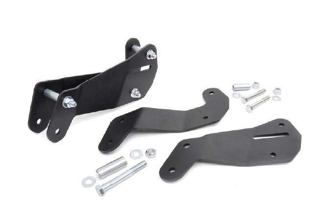
KIT CONTENTS