FREE 1 to 3-Day Delivery on Orders $149+ Details

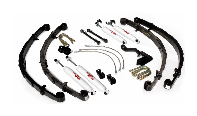
How to Install Rough Country 6 In. Suspension Lift Kit on your 1987-1995 Wrangler
Tools Required
- Floor Jack
- Jack Stands
- 13/16"Deep Well socket
- 13mm Wrench
- 18mm Wrench
- 19mm Wrench
- 15mm Wrench
- 21mm Wrench
- 22mm Socket
- 9/16"Wrench
- 3/4"Wrench
- T55 Torx Socket

Shop Parts in this Guide
FRONT INSTALLTION
1. Place the vehicle on a level surface. Set the parking brake. Center front wheels and chock rear wheels.
2. Raise the front of the vehicle and support with jack stands.
3. Remove the front tires/wheels, using a 13/16” deep well socket.
4. Support the front axle housing with a floor jack (you must have jack stands under the frame supporting vehicle weight).
5. Using a 19mm wrench, unbolt the track bar from the axle housing, on the passenger side of the axle and tie the track bar up and out of the way.
6. Using a 19mm wrench remove the front sway bar links by removing the factory bolts, and nuts.
7. Remove the front axle u-bolts using a 19mm socket.
8. On the drivers side position a floor jack beneath the axle tube, just inside of the leaf spring. Raise the jack until the axle separates from the spring.
9. Using a 21mm socket, and 22mm wrench remove the shackle bolts from the leaf spring. Repeat on the passengers side.
10. The new leaf springs may have larger center pins than the stock springs. If so you must clearence the spring perch to 9/16”. Be careful not to penetrate the axle tube.
11. Prior to installation of new springs, thoroughly lubricate the new spring eye bushings and sleeves with a water resistant, lithium based grease. Loosely attach the front spring, (part # 8014) into the front and rear spring hanger, snug but do not completely tighten. Make sure the spring tie bolt head aligns into the spring perch.
12. Install new u-bolts using a 191mm socket, be sure to tighten the u– bolts in an x pattern. Tighten to 65
ft. lbs.
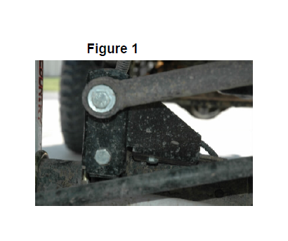
13. To install the new track bar bracket onto the front housing, place
the track bar bracket on the stock mount where the flange matches with the stock flange on the right side of the bracket. Using a 19mm wrench install the supplied 12mm x 2” long bolt, washer and flange lock nut from 1622bag2 to secure, torque to 45 ft/lbs. Using the hole in the new bracket as a guide, drill a 3/8” hole through the stock flange of the track bar housing. Install the 3/8” x 1 1/4” bolt, washer, and 3/8” flange lock nut, using a 9/16” wrench. Torque to 35 ft/lbs. See Figure 1.
14. Attach the bar to the bracket, using the supplied 12mm x 2 1/2” bolt, flat washer, and 12mm flange lock nut, using a 19mm wrench. Torque to 45 ft/lbs.
15. Assemble shocks bushings into front shock # 650341.
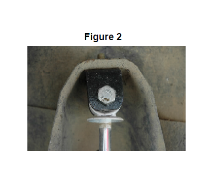
16. Install the supplied shock hoop bracket to the factory mount using the supplied 3/8” x 1.25” bolt, washer and nut, using a 9/16” wrench. Using the supplied 12mm x 65mm bolt from 1622bag4, install the front shock into the new shock hoop bracket, using a
19mm socket. Install the bottom of the shock into the stock mount. Tighten the bottom mount until the bushing starts to buldge. See Figure 2
17. Assemble the quick disconnect link body and link ends with the supplied double wire hitch pin. Insert the sleeves from 1186bag into the bushings. Using the supplied 12mmx 65mm bolts, washers and nuts, install link using a 19mm wrench into the factory brackets.
18. Remove front stock brake lines
19. Install the new Rough Country brake hoses. Route the new hoses in the same manner, and use the new attaching hardware.
20. It is important to not tighten the spring and shackle bolts at this time. If the springs are tightened with no load being applied on the springs, a false lift and stiff ride will result. These bolts will be tightened once the vehicle is lowered and weight applied to the springs.
21. Install tires/wheels, remove jack stands and lower vehicle to floor. Tighten the front spring’s shackle to 95 ft. lbs. and the stationary end to 105 ft. lbs, using a 21mm wrench and 22mm socket.
REAR INSTALLTION
1. Once again as on the front (following same basic steps). Place safety (jack) stands under rear frame rails. Figure 2
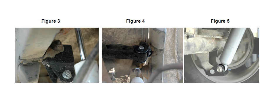
2. Disconnect rear track bar from frame rail on the passenger side of the vehicle, using a T55 torx socket. Install new drop down tracking bar mounting bracket on frame rail by placing it into the old mounting point and installing 5/16” x 1” long bolt, nut and washer, using a 13mm wrench from 1622bag2 into the tab hole on the bracket. Using factory hardware in stock mounting location and supplied 12mm-1.75 x80mm long
bolt, nut and washer, from 1622 bag2 in new drop location secure track bar, using a 19mm wrench. Note– it may be easier to install track bar into bracket when vehicle is on the ground. See Figure #3 & 4.
3. The new leaf springs have larger center pins than the stock springs. You must drill the spring perch to 9/16”, being careful not to drill to deep.
4. Prior to installation of new springs, thoroughly lubricate the new spring poly eye bushings and sleeves with a water resistant, lithium based grease. Install new springs with shims, using a 21mm wrench, and 22mm socket. When installing the springs the thick part of shim goes toward front of jeep. Do not fully tighten the springs and the track bar to factory specs until the vehicle is on the ground. Tightening before the weight is on the vehicle may prevent the shackles from moving to their natural position and result in the arched spring being pinned forward against the frame.
5. Attach tracking bar to drop down bracket using original 12mm bolt and flange nut. Using a 19mm wrench torque to 45 ft. lbs.
6. Install the rear shock relocator as shown with the 12mm x 65 bolt from 1185bag in the stock location, using a 19mm wrench.. Locate and install the supplied 5/16 bolt in the bracket and stock mount, using a 13mm socket. Tighten hardware. See Figure 5.
7. Assemble the rear shock absorbers. Part# 650328 with loop bushings and corresponding sleeves and install shocks, torque upper and lower mounts to 45-ft. lbs.
8. Remove the factory rear brake hose.
9. Install the new Rough Country rear brake hose. It should be identical to the factory hose except for the length. Route the new hose in the same manner, and use the stock attaching hardware
10. Install tires; using a 13/16” deep well socket. Remove jack stands and lower vehicle to floor. Tighten the shackle to 95 ft. lbs. and the frame end to 105ftlbs. Install/tighten track bar into drop down bracket.
11. Tighten the rear springs using a 21mm wrench, and 22mm socket. Torque bolt to 65 ft. lbs.
PITMAN ARM INSTALLTION INSTRUCTIONS
1. With the tire on the ground the full vehicle weight on the suspension, move the steering left to right, check the following for looseness, slack and wear: steering sector-to-frame attaching points, steering sector main (output) shaft, drag link and tie rod ends, trac-bar mounting points and bushings.
2. With the tires off the ground, check for improper wheel bearing pre-load and ball joint wear. IT IS VERY IMPORTANT that all steering related parts are in proper working condition. If any problems exist, repair before proceeding
3. Remove the cotter pin and nut from the drag link end where it attaches to the pitman arm. Dislodge link with a tie rod end remover tool or a pickle-fork. NOTE - replace the link if any stud looseness is detected or if you can twist the stud in its socket with your fingers. Remove the pitman are from the steering sector output shaft using a puller tool. Inspect the shaft splined for excessive wear, repair if needed
4. The arm and shaft splines should be clean and free of grit. Install new arm, lock washer and nut; torque to 170 ft. lbs
5. Attach the cleaned drag link stud to the pitman arm. Torque slotted nut to factory specifications and install cotter pin. NOTE - If the drag link end stud is tightened in a position other than the straight ahead position or allowed to twist in the adjustment collar, vehicle drift to the left or right could occur
6. Lower the truck to the ground. Check for adequate linkage clearance while turning steering wheel lock to lock. Re torque drag link ends if loosened, and double check cotter pins..
7. Have toe-in adjustment set to factory specs Figure 4
TRANSFER CASE INSTRUCTIONS
1. If you are not installing a slip yoke eliminator, and driveshaft follow the following instruction to install the transfer case drop brackets. NOTE- The slip yoke and drive shaft is highly recommended for the 6” kit. Vibration will be present if only the transfer case lowering kit is used.
2. Place floor jack under transmission mount skid plate. Make sure the jack is centered.
3. Using a floor jack, support the skid plate.
4. Slightly loosen the bolts on the transfer case skid plate on both sides to allow for some movement. Do not remove the bolts
5. Proceed to either side. NOTE: Do not attempt to take out the bolts on both sides simultaneously. Installation is done one side at a time. Remove the three bolts holding the transfer case skid plate to the frame rail. Note: It may be necessary to loosen the bolts holding the transfer case to the skid plate to allow for movement to install the lowering spacers on the skid plate
6. Using the floor jack, slightly lower the skid plate and insert the transfer case lowering spacer. The spacer has a front and back (the holes line up in only one direction). When the transfer case is dropped it will tend to move forward, to get the new bolts to align with holes in frame rail you will probably have to push the transfer
case skid plate towards the back of the vehicle
7. Using the bolts and conical washers supplied slightly tighten the bolts. Be sure that the tapered end of the washer is facing toward the bracket. Do not fully tighten to allow for some movement for the opposite side.
8. Proceed to the opposite side of the vehicle and install the brackets as instructed above. After installing both sides, tighten bolts– do not over tighten.
9. It may be necessary to remove some material from the body underneath the shifter on the manual shift models to allow clearance for shifting into all gears. To accomplish this, remove the shifter boot from the shifter. Go through the shift pattern and note where the shifter is coming in contact with the body. Remove approximately ¼”- 3/8” of material from the body with a small grinder. Go through the shift pattern again and note any contact. Trim accordingly. Reinstall the boot and secure.
POST INSTALLATION
1. Check and recheck all fasteners for proper torque. Check to ensure there is adequate clearance between all rotating, mobile, fixed and heated members. Check clearance between upper control arm and sidewall of tire for proper clearance. Check steering for interference and proper working order. Test brake system.
2. Perform steering sweep. Cycle the steering from full turn to full turn to check for clearance. Failure to perform inspections may result in component failure.
3. Re torque all fasteners after 500 miles. Visually inspect components and re torque fasteners during routine vehicle service.
4. Adjust headlights to proper settings given increased vehicle height.
MAINTENANCE INFORMATION
It is the ultimate buyers responsibility to have all bolts/nuts checked for tightness after the first 500 miles and then every 1000 miles. Wheel alignment steering system, suspension and driveline systems must be inspected by a qualified professional mechanic at least every 3000 miles.