 FREE 1 to 3-Day Delivery on Orders $149+ Details

How to Install Rough Country 30 in. Chrome Series LED Light Bar w/ Hood Mounting Brackets (2018 Jeep Wrangler JL) on your Jeep Wrangler
Installation Time
60 minutes
Tools Required
- Trim Removal Tool (Plastic or Wood to prevent scratches on the paint)
- Hex (Allen) Key (4mm)
- Ratchet (3/8”)
- Sockets (13, and 15mm)
- Wrench (10mm)
- Towel (To protect the paint)
- Wiper Removal Tool (optional)

Shop Parts in this Guide
Note: Park the vehicle on a safe and leveled surface and wear protection gear.
Installation Instructions:
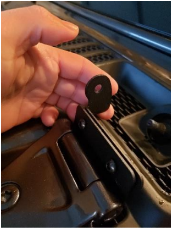
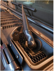
1. Pop off the plastic cap on top of the windshield wiper nut.
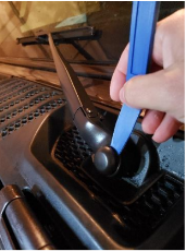
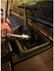
2. Using a 15mm socket, remove the nut.
3. Flip the wiper blade away from the windshield after unbolting. This will help release the tension against the bolt and facilitate the blade removal. You might need to use a wiper removal tool or an alternative method.
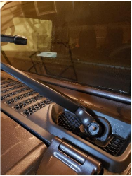
4. Repeat on the other side.
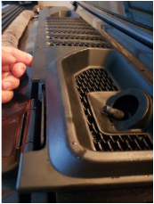
5. Using the trim removal tool start detaching the edge of the plastic cowl cover. Then continue detaching all the clips and set the cover aside.
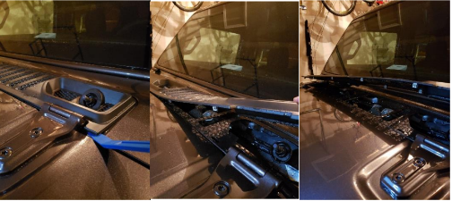
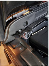
6. Using the 13mm socket, loose the two bolts holding the hood hinge behind the cowl cover. Do not fully remove the bolts, you will only need a small separation of the screw head and washer to slide the lower portion of the mounting bracket in.
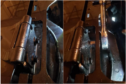
7. Slide in the lower portion of the mounting bracket ensuring that the bend on the bracket points towards the windshield. Tight the bolts and repeat in the other side.
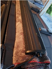
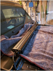
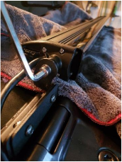
8. Fold the towel, place top of the cowl and rest the light bar on top of it. The power cable of the light bar should be facing the passenger’s side.
9. Open the hood and support it with the prop rod.
10. Tuck in the cable close to the passenger’s side hood hinge between the cowl and the hood.
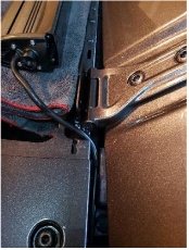
11. Leave a little slack and slide under the foam cover that is inside the hood.
12. Close the hood and place the towel and the light bar on top of it.
13. Lay the cowl cover back in place and press in all the 12 clips. The fit will be tight. It is advised to start in the driver’s side by insert the wiper screw in the cowl cover and then slide in behind the lower portion of the bracket.
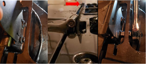
14. Place the top portion of the bracket with the round light bar mounting point aimed towards the inside (driver’s side shown). Make sure the top portion of the bracket is installed behind the lower portion of the bracket. Now loosely secure using the provided hardware (70048BAG1). Repeat on the other side.
15. Reinstall the windshield wipers, tighten using a 15mm wrench and put the plastic cap back on top of the wiper blade nut.
16. Extend the towel so it spans over the top of the cowl plastic cover and the hood, this will prevent scratches in the hood and cowl area while mounting the light bar to the brackets.
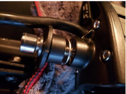
17. Using the hardware provided attach one side of the light bar to the bracket loosely. Make sure the locking washer goes first, then the bracket, then the spacer, then the washer. Repeat in the other side.
18. Using a 4mm hex key and a 10mm wrench, tight down the bolts on the brackets.
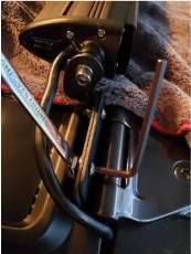
19. Aim the light towards the desired position and tight using the provided hex key.
20. Now the towel can be removed and you can start working in the wiring.
21. Every build is unique and there are many ways to run the wiring and install the on/off switch. You should consider among other things the other electronics in your build (current and future) and then plan how to route the wires. Some guiding principles should be followed as follows:
a. Plan ahead where the on/off switch will be mounted.
b. Route the harness to the mounting location but don’t secure (e.g. zip-tie) until all connections have been performed.
c. Avoid sharp edges, abrasive surfaces and heat sources.
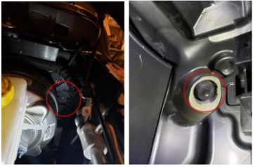
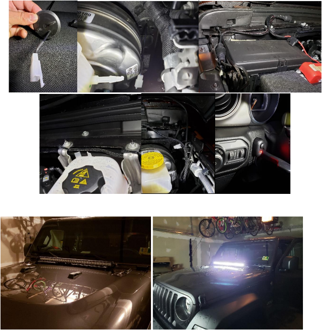
22. There are two firewalls on the JL. The easier to access is the one the driver’s side (shown below). The one on the passenger’s side is more difficult to access as it sits in about the same area but is covered by the back-up battery. The first pic below shows the firewall in the driver’s side from the engine bay and the second picture from the inside of the vehicle.
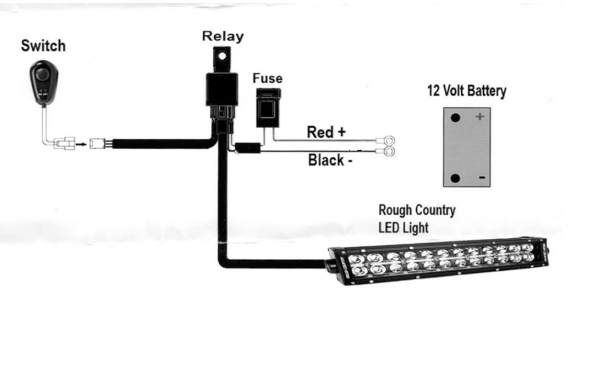
23. See the wiring diagram below. Note that the black cable can be connected to the negative terminal of the battery (as shown below) or to a suitable ground.
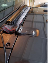
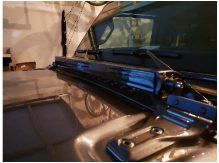
24. Below are some pics of a sample installation.
Installation Instructions Written by ExtremeTerrain Customer Duamel Santiago 11/25/2018

