FREE 1 to 3-Day Delivery on Orders $149+ Details

How to Install Rough Country 1.25" Body Lift Kit on your 1997-2006 Wrangler
Tools Required
- Floor jacks
- Wood Blocks
- Wheel chocks
- Torque wrench
- 1/2 drive ratchet
- 5/8" socket/wrench
- 3/4" socket /wrench
- Safety glasses
- Thread locker
BODY LIFT INSTALLATION INSTRUCTIONS
1. Make sure the vehicle is on a level smooth surface.
2. Loosen the 11 body bolts using a 5/8” socket. Do not remove the stock bolts at this time.
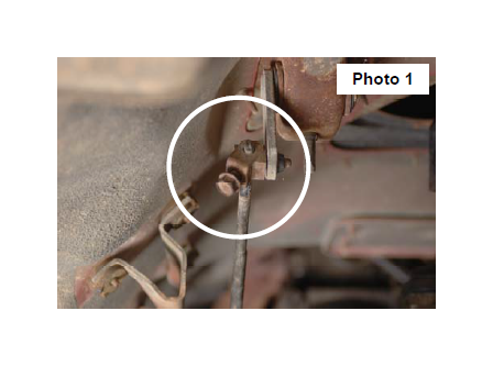
3. Remove the front body mount bolt as shown in Photo 1. Remove either the 5 passenger side bolts or the 5 driver side bolts. Do not remove both sides. Installation is performed one side at a time.
4. Using a floor jack slowly jack up the body of the Jeep and insert the supplied body lift blocks between the body and the three side cab mount bushings as shown in Photo 2. Take caution to keep your hands out from between the frame and the body. The three side body mounts will be secured with the supplied 1/2” x 4 1/2” bolts. Apply
thread locker to the bolts and install. Do not tighten at this time.
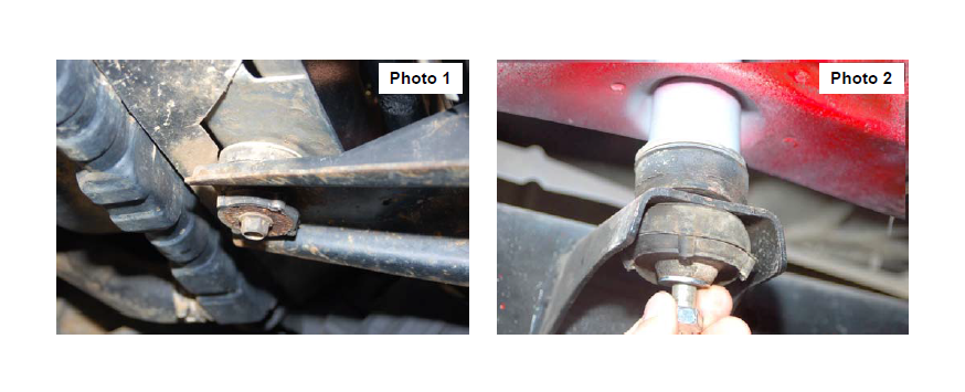
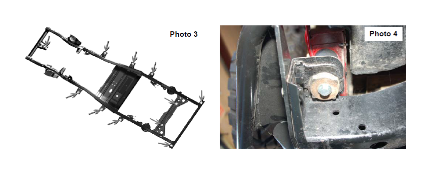
5. Insert the supplied body lift blocks in the 4 rear most mounts. Apply thread locker to the supplied 7/16” x 4” bolts and install. Photo 3 shows all body mounts. Rear corner mount shown in Photo 4. Do not tighten at this time.
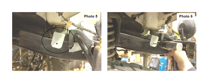
6. Place the new radiator core support bracket in place and mark hole to be drilled. See Photo 5.
7. Drill the hole using a 9/32” drill bit. See Photo 6.
8. Secure using the bracket to the frame with the supplied 5/16” x 1” self tapping bolt. Tighten using a 1/2” wrench.
9. Slowly lower the body onto the body mounts.
10. Proceed to opposite side and install the body lift blocks as installed on the previous side.
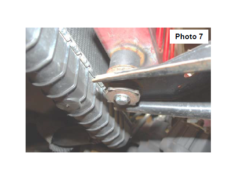
11. Install the front body spacer as shown in Photo 7. Apply thread locker to the supplied 7/16 x 4” bolt and install.
12. Tighten all body bolts to 30-35 ft/lbs. Do not over tighten. Over tightening the body mount bolts could crush the factory body mounts.
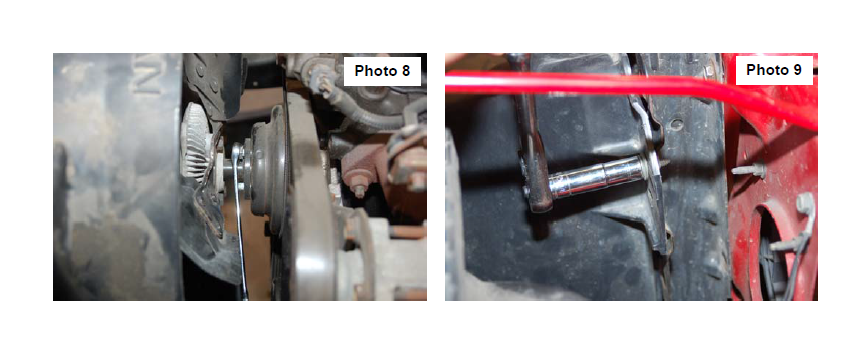
13. Remove the fan from the motor as shown in Photo 8 using a 1/2” wrench. Save the hardware for reuse.
14. Remove the power steering reservoir from the fan shroud to allow it to be removed
15. Remove the fan shroud using a 7/16” wrench. See Photo 9. Save the factory hardware for reuse.
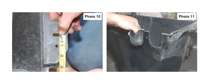
16. Measure 1 1/4” up as shown in Photo 10 and drill the shroud using a 1/4” bit. The lower passenger side hole will line up with an existing factory hole and will not require marking with a center punch. On 6 cylinder models, it may be necessary to remove a small portion of the fan shroud webbing to allow the 1/4” hole to be drilled.
17. Test fit the fan shroud to the radiator by aligning with the new mounting holes and mark the location where the lower radiator hose interferes with the fan shroud. Trim the fan shroud until it completely clears the radiator hose when mounted to the radiator. Reinstall the fan with factory hardware using a 1/2” wrench and check for interference between the fan shroud and fan blades, or any other objects, and trim the fan shroud accordingly.
18. Secure the shroud to the factory location with factory hardware using a 7/16” wrench. Tighten all hardware.
TRANSFER CASE SHIFTER BRACKET INSTALLATION INSTRUCTIONS
These next steps will be necessary if the vehicle is equipped with a transfer case drop kit. If the vehicle does NOT have a transfer case kit installed the bracket should NOT be installed. The bracket is designed to adjust the 4WD shifter allowing the full range of the shift pattern. After drop bracket installation, check the
operation of the 4WD shift lever to ensure the transfer case engages fully in all ranges. Additional “fine tuning” can be performed if the shifter does not fully engage in all the ranges. Refer to instructions on the next page to adjust the shift linkage. It may also be necessary to trim the body under the middle console to avoid interference with the shifter.
1. From underneath the vehicle, locate the shift control bracket. It is attached to the inside of the transmission tunnel on the driver side and acts as a pivot for the transfer case shift lever.
2. Remove the shifter linkage from the shifter plate that is mounted on the body tunnel as shown using a 10 mm wrench.
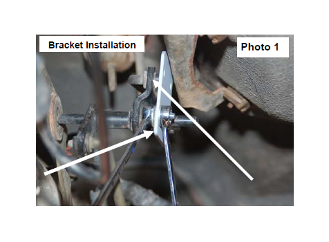
3. Reinstall the stock shifter bracket on the new drop bracket as shown with the 1/4” x 3/4” hardware. Tighten using a 7/16” wrench. See Photo 1.
4. Install the supplied drop bracket on the stock tunnel bracket with the supplied 1/4” x 3/4” bolts/washers & nuts. Tighten hardware using a 7/16” wrench. Check clearance on bolts. See Photo 1.
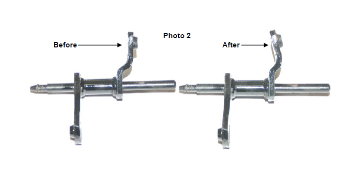
Due to factory variations on the shifter rod bracket, it may be necessary to modify the shifter bracket by slightly bending the mount on the rod to clear the shifter bracket or shifter bracket bolts. After noting how much to bend the bracket to clear, remove the shifter assembly and bend the bracket as shown to slightly clear the bracket / bolts. Do not over-bend!! See Photo 2.
SHIFTER LINKAGE ADJUSTMENT INSTRUCTIONS
If the 4WD shifter engages in all ranges, the following procedure will NOT be necessary.
1. Check the transfer case shifter to see if it will move to 4L. If not, the linkage will need adjusting. Place the shifter in 4L, loosen adjustment bolt and push the linkage forward until it
stops. Now re-tighten adjustment bolt. See Photo 1. Check to be sure 4WD works properly.
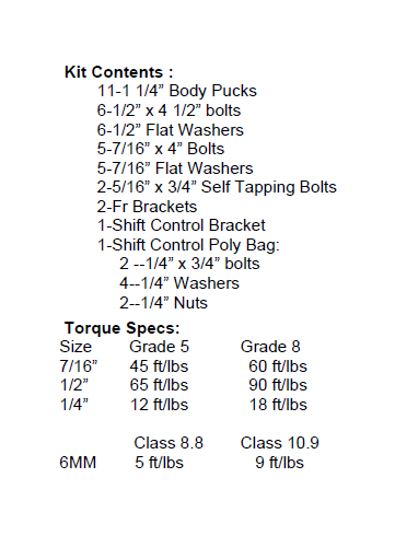
MAINTENANCE INFORMATION
It is the ultimately the buyers responsibility to have all bolts/nuts checked for tightness after the first 500 miles and then every 1000 miles or 3 months. Wheel alignment steering system, suspension and driveline systems must be inspected by a qualified professional mechanic at least every 3000 miles.