 FREE 1 to 3-Day Delivery on Orders $149+ Details

How to Install Rough Country 1 In. Body Lift / Body Mount Kit on your 1987-1995 Wrangler
Tools Required
- Floor Jack
- Jack Stands
- 3/8" Socket / Wrench
- 1/2" Socket / Wrench
- 5/8" Socket / Wrench
- 13mm Socket / Wrench
- 19mm Socket / Wrench
- Drill Motor
- 1/4" Drill Bit

Shop Parts in this Guide
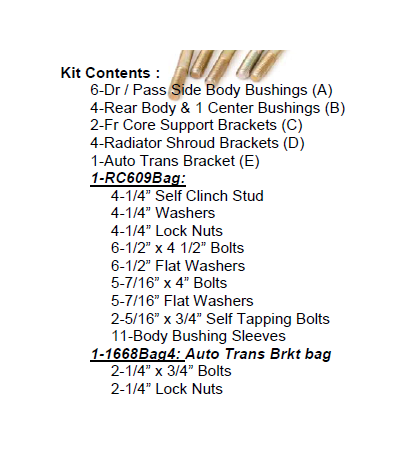
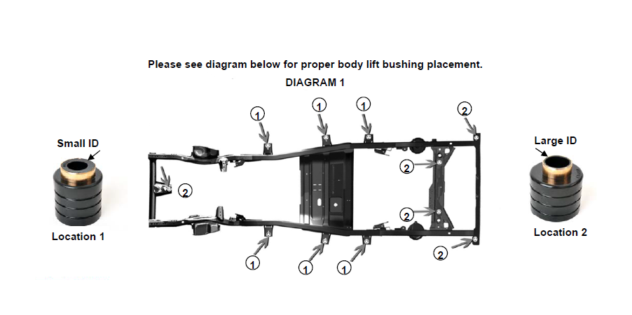
Please see diagram below for proper body lift bushing placement.
INSTALLATION INSTRUCTIONS
1. Disconnect the negative battery cable using 1/2” wrench.
2. Remove the plastic jeep cover from front of vehicle using a 3/8” wrench and the metal plate that secure the brake line.
3. Disconnect air intake from air filter housing and from throttle body. Depending on year remove coolant reservoir and power steering reservoir from fan shroud.
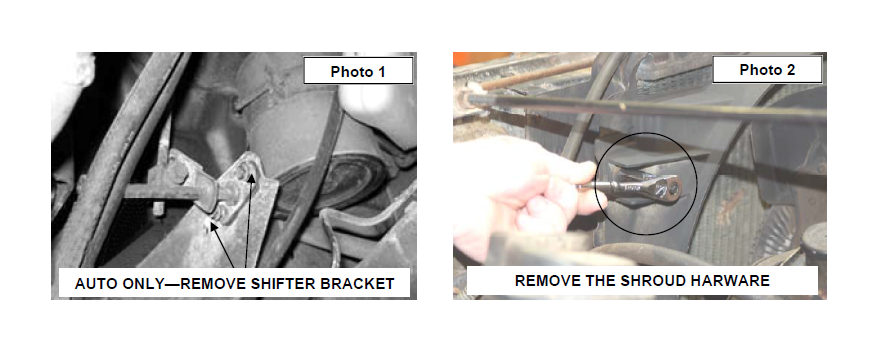
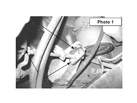
4. (AUTO TRANSMISSION ONLY) Remove the linkage on the frame to allow the body to be moved up by removing the two bolts and remove the cotter pin securing it to the engine bracket. Allowing the shifter cross shaft to hang freely. Retain hardware for reuse. See Photo 1.
5. Remove the 4 bolts from radiator shroud using a 13mm socket. See Photo 2.
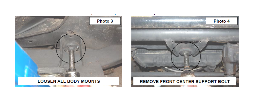
6. Loosen all eleven body mount bolts using 5/8” socket. There is one in center of grill, three under each door, two above rear axle and two at each rear corner. See Photo 3.
7. Only remove bolts on one side at a time. Front center bolt must be remove for both sides. See Photo 4.
8. Using floor jack or jack stand and a wood block raise body from frame only enough to safely install the body puck.
Take Caution not to over extend wires, brake lines, cables and steering shaft.
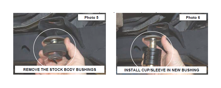
9. Remove the steel cup / sleeve from the stock body bushings. See Photo 5 The steel cup/ sleeve will be reused.
10. Reinstall the steel cup / sleeve from the stock body bushing in the new body bushing. See Photo 6.
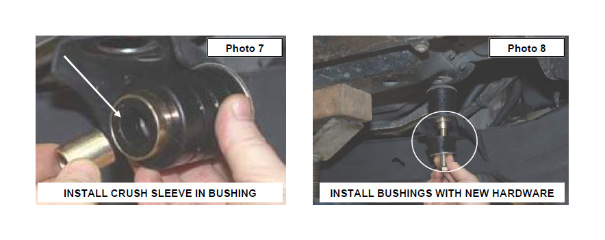
11. Install the supplied crush sleeve in the new body bushings with the smaller inner diameter hole. See Photo 7.
12. Install the bushings in the 3 side body locations marked 1 in the Diagram 1.
13. Remove the stock 2 rear most body bushings and center front body bushing marked 2 in Diagram 1.
14. Insert the supplied large diameter body bushings in the 2 rear most mounts and center front mount.
15. Repeat for opposite side.
16. Apply thread locker to the supplied 1/2” x 4 1/2” bolts and install the lower bushing / crush sleeve and washer on the 3 side body mounts. See Photo 8. Do not fully tighten at this time.
17. Install the lower bushing / crush sleeve and washer in the 4 rear mounts. Apply thread locker to the supplied 7/16” x 4” bolts and install. Do not tighten at this time.
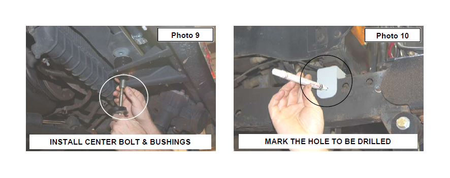
18. Apply thread locker and install the 7/16” x 4” bolts, washer and crush sleeve in the front center mount. See Photo 9. Do not tighten at this time.
19. Install the new front bump stop extension under the bump stop on radiator core support. Using the bracket as a template mark hole to be drilled. See Photo 10.
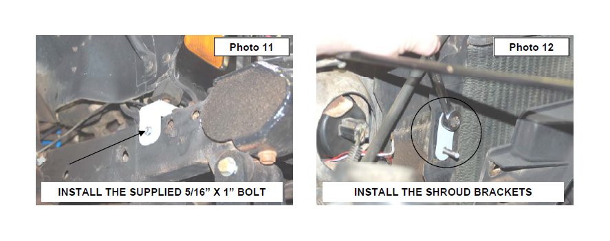
20. Drill a 1/4” hole in frame and secure using the supplied 5/16” x 1” self tapping bolt and a 13mm socket to tighten. See Photo 11. Do not over tighten the bolt. Repeat for the opposite side.
21. After all body puck are in tighten all bolts. 19mm socket for the 1/2” bolts and 16mm for the 7/16” bolts.
22. Install the 1/4” clinch studs into radiator drop bracket using hammer and small socket
23. Install the four radiator fan shroud drop brackets using stock hardware. See Photo 12.
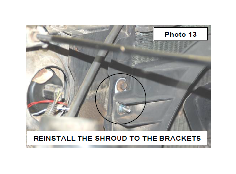
24. Reinstall the shroud on the bracket with the supplied 1/4” lock nuts and flat washers. See Photo 13.
25. Reinstall the coolant reservoir and power steering reservoir to the fan shroud if applicable. Use a 13mm for stock bolts and 7/16” for new nuts.
26. Reconnect the air intake to the air filter housing and throttle body.
27. Reinstall plastic jeep cover and metal plate using 3/8”
socket. Metal plate should go under the body mount. Install hard brake line back into clips.
28. (AUTO TRANSMISSION ONLY) Proceed to installation instructions for automatic shifter bracket.
29. Re-Check all fastener to confirm all components are not binding or in the way of moving parts.
AUTOMATIC SHIFTER BRACKET INSTALLATION(FOR VEHICLE EQUIPPED WITH AUTOMATIC TRANSMISSION ONLY)
1. Using the supplied shifter location bracket, mount to the stock shift linkage bracket with the supplied 1/4” hardware and tighten. Note: The bolts will point toward the engine.
2. Mount the assembly in the stock location on the engine
bracket and secure with stock cotter pin.
3. Mount the assembly in place on the original frame location
with the stock hardware and tighten. See Photo 1.
POST INSTALLATION INSTRUCTIONS
1. Check all fasteners for proper torque. Check to ensure there is adequate clearance between all rotating, mobile, fixed and heated members. Check steering gear for interference and proper working order. Test brakes.
2. Check to ensure metal brake lines have sufficient slack to eliminate interference and maintain proper working order. Failure to perform inspections may result in component failure. Readjust headlights to proper settings.
MAINTENANCE INFORMATION
It is the buyers ultimate responsibility to have all bolts/nuts checked for tightness after the first 100 miles and then every 1000 miles. A qualified professional mechanic must inspect wheel alignment steering system, suspension and driveline systems at least every 3000 miles.
