FREE 1 to 3-Day Delivery on Orders $149+ Details

How to Install a Rock Krawler 5.5 in. X Factor Plus Long Arm System w/o Shocks on your 1997-2002 Jeep Wrangler TJ
Dear customer:
Thank you for purchasing the best system on the market for your Jeep Vehicle. We are sure you will be happy with this system after your installation is complete. Please take your time during the installation and be sure to do it correctly. Completely read the directions before starting your installation so you know what to expect. Remember, your personal safety depends on it. Should you have any questions during this installation feel free to give our tech line a call (518-270-9822) and we will be happy to help you.
Note:
BE SURE TO CHECK ALL FASTENERS FOR PROPER TORQUE BEFORE TEST DRIVE. RECHECK AFTER 500 MILES AND BE SURE TO CHECK PERIODICALLY.
Warning:
Read and understand all instructions, warnings and safety precautions in these instructions and your owner’s manual before attempting to install these components.
Caution:
Proper installation of Rock Krawler Suspension, Inc. Products requires knowledge of recommended procedures for disassembly/assembly of OE vehicles and components. Access to OE shop manuals and special tools are required. Attempting to install this kit without knowledge of these procedures may affect the safety of your vehicle and or the performance of these components. Rock Krawler Suspension, Inc. strongly recommends that this system be installed by a certified mechanic with off road experience.
Warning:
Rock Krawler Suspension, Inc. does not recommend combined use of suspension lifts, body lifts or other lift devices. Combined use of lifts may result in unsafe and unexpected handling characteristics. Also, many states now have laws restricting Vehicle lift, bumper heights and other alterations. Consult local laws to determine if your proposed alterations (including installation of this system) comply with your state laws.
Caution:
Rock Krawler Suspension Inc. recommends the use of locktite on all hardware, unless noted otherwise
Warning:
Properly block and secure vehicle prior to installation.
Always wear safety glasses when using power tools.
Rock Krawler Suspension Inc. does not condone or authorize the use of any other suspension components with its products. Should Rock Krawler Systems or components be installed in junction with other products or not per the provided instructions Rock Krawler Suspension Inc.’s warranty is void and is not to be held accountable for any resulting actions.
The use of limiting straps is recommended to avoid possible damage from over extending the suspension of your vehicle.
Helpful hint:
Do not tighten connections until assemblies are installed in entirety.
Driving Tips:
1) For Rock Crawling it is best to have the front sway bar disconnected. This will allow your suspension to do its intended function. Our suspension will give your vehicle unmatched articulation which will give you traction to keep your vehicle moving. Let the system do the work. This will save on vehicle abuse.
2) For Mud, especially sloppy mud, it is best to have the front sway bar connected. This will limit the suspension travel which is better for mud.
3) For Highway driving it is best to have the front sway bar connected. This will give you the on highway ride and handling characteristics you expect. If you choose otherwise, you do so at your own risk.
Reference Lengths:
If you got a 3.5” System
3.5” Front Track Bar Assembled Length = 32.625”
3.5” Rear Track Bar Assembled Length = 39.75”
3.5” Front Lower Control Arm Assembled Length = 34.125”
3.5” Front Upper Control Arm Assembled Length = 36.25”
3.5” Rear Lower Control Arm (2 Door) = 33.625”
3.5” Rear Lower Control Arm (4 Door) = 34.500”
3.5” Rear Upper Control Arm (2 Door) = 27.250”
3.5” Rear Upper Control Arm (4 Door) = 26.750”
If you got a 5.5” System
5.5” Front Track Bar Assembled Length = 32.625”
5.5” Rear Track Bar Assembled Length = 40.00”
5.5” Front Lower Control Arm Assembled Length = 34.250”
5.5” Front Upper Control Arm Assembled Length = 36.313”
5.5” Rear Lower Control Arm (2 Door) = 33.750”
5.5” Rear Lower Control Arm (4 Door) = 34.625”
5.5” Rear Upper Control Arm (2 Door) = 27.375”
5.5” Rear Upper Control Arm (4 Door) = 26.875”
5.5” Rear Lower Control Arm (2 Door STRETCH) = 40.4375”
5.5” Rear Upper Control Arm (2 Door STRETCH) = 33.625”
Please Note: All Control Arms, Torque Arms, and Track Bars come pre-assembled, but they require final adjustment as specified in the directions above.
Please note:
Before you start this procedure it is recommended that you have your front exhaust modifications completed prior to installation of the system so when your installation is completed you can drive your JK away safely. The recommended exhaust modification is shown below.
Exhaust Cut and O2 Sensor Relocation
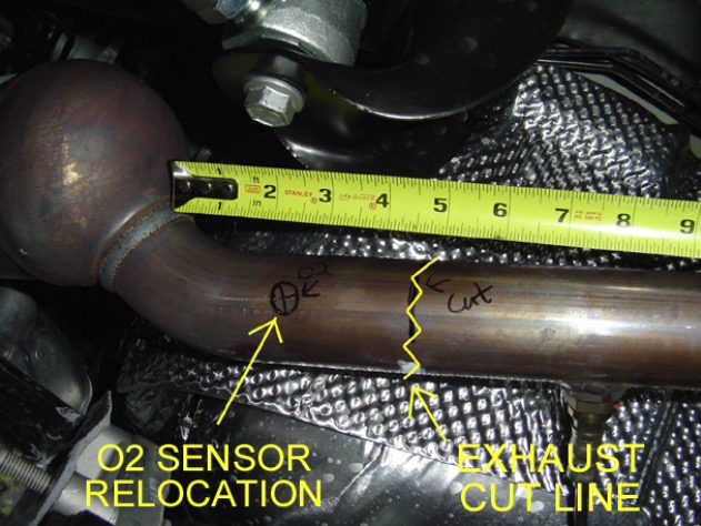
A) Remove the O2 Sensor and then cut the exhaust 4.5” back from the catalytic converter. Relocate the O2 Sensor 2.5” from the end of the first cat. Please note: the O2 Sensor will actually function better the hotter it is so moving it closer to the manifold will certainly not hurt its operation.
Relocated Resonator after the Cat on the Driver’s Side
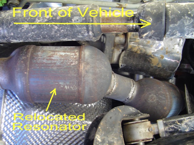
B) After Relocating the O2 Sensor forward (it must be relocated between the cat and the resonator) flip the resonator over 180 degrees and weld it back in place as shown above.
Cross Over Pipe Modification
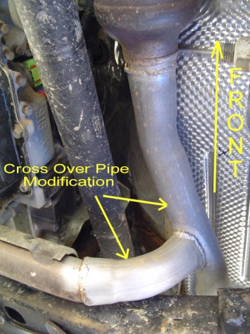
C) Modify the cross over pipe and tie the driver’s side resonator into the exhaust connection and then bring the entire exhaust system back together. Make sure your modifications allow for clearance for the new mounts and mounting hardware for the arms. All set. Time to knock out the rest of the kit.
Start with the Front End
1. Make sure vehicle is still on a level hard, working surface. Block the rear wheels so the vehicle cannot move and make sure the emergency brake is applied. Raise the front of vehicle and support with safety jack stands. Locate jack stands on the frame in front of the axle.
2. Remove the front rims and tires.
3. Support the front axle housing using a hydraulic floor jack.
4. Remove the front shocks. Keep the original hardware to install the new shocks.
5. Remove the front sway bar links.
6. Lower the front axle assembly.
7. Remove the front track bar from the vehicle and save the OEM hardware for reuse.
8. Remove the front springs.
9. Remove the front lower control arms. Discard the arms, but save the hardware for reuse.
10. Remove the front upper control arms and discard the arms and hardware for they will no longer be used.
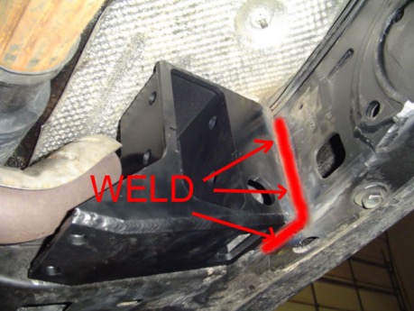
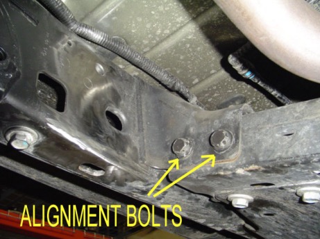
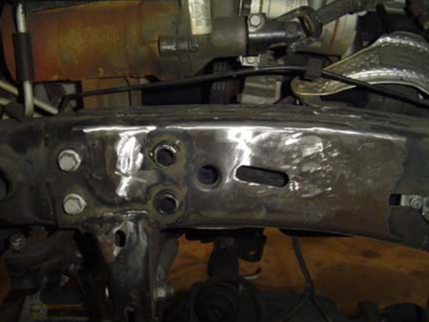
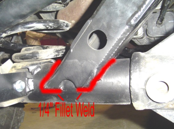
11. Install the front long arm mounts. The mounts bolt into position using the OEM cross member bolts and then weld in place. Use a full ¼” fillet weld. Be sure to prep the surfaces properly and after the welds cool apply a durable finish of your choice.
D.S. Bracket Location Bolts
D.S. Bracket Welded in Place
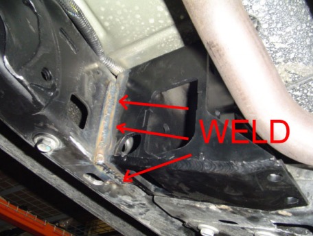
P.S. Bracket Location Bolts
P.S. Bracket Welded in Place
12. Install the new cross member using the (4) supplied ½” x 1.25” long black oxide coated carriage bolts, ½” lock washers, and ½” free running nuts.
13. Now is a good time to remove all the OEM front lower control arm mounts from the frame. Be sure to grind them smooth. You are also required to remove the driver’s side OEM front upper control arm mount from the frame and grind it smooth. It will interfere with the new front upper control arm. You may also remove the passenger side OEM front upper control arm mount from the frame and the passenger side front upper arm mount on the axle. This will make your JK look it’s best when the system is installed and completed. Remember, it may take a few minutes longer, but in the long run your attention to detail will pay off in looks, performance and durability.
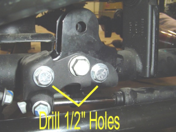
14. For all 5.5” Systems (3.5” Systems omit this step); Install the front track bar bracket. Grab the front track bar bracket and secure it in position as shown below using the OEM lower track bar hardware. Then drill out the other two holes in the OEM bracket through the supplied bracket with a ½” drill bit as shown below. Then, finish securing the new bracket with the supplied ½” x 3” bolts, ½” washers, and ½” nylok nuts.
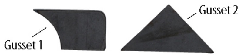
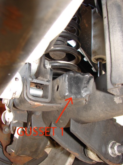
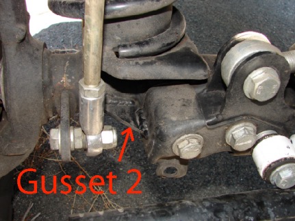
15. For all 5.5” Systems (3.5” Systems omit this step); Install the supplied front track bar gussets as shown below. Please note they require welding. It is not critical that they be done immediately for street use, but for off-road use this is required…. Install gusset 1 on the inside and weld it in place. This will box in the open section of the OEM track bar mount where the failures start off-road. Then install gusset 2 on the outside of the bracket as shown below and weld it in place. A 1/8 inch fillet weld is preferred for these brackets. This will make your OEM track bar mount much more rigid for off-road abuse!
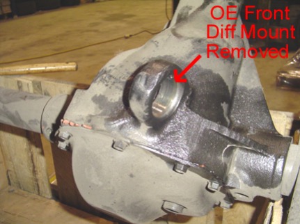
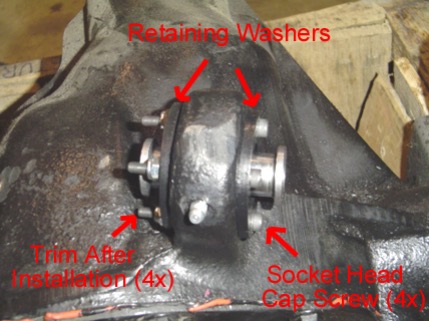
16. Now it is time to make the stock front upper control arm mount on the driver’s side into a re-build-able, flexible joint.
First, pound out the driver’s side OEM front upper control arm bushing and sleeve. Note: It is easier if you hit on the steel sleeve. If you run into trouble drill out the rubber bushing material and then remove the entire assembly.
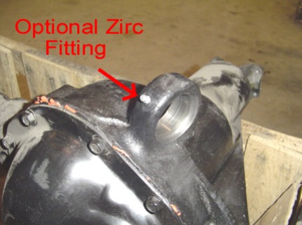
Second, (this is optional, but is recommended, if you choose not to do this step please pack the joint with grease prior to final assembly) drill and tap a hole through the front of the housing as shown to allow for the supplied grease fitting to be installed. Make sure the hole is centered in the housing. Use a .162 to .166 inch diameter drill bit and a #10-32 tap. Clean out the housing of any drill chips or debris.
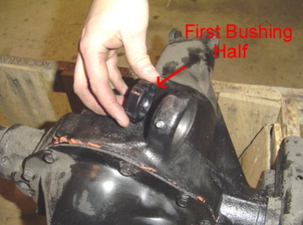
Third, take one of the supplied ball joint bushings and push it in one side. Note: make sure the slots for the fasteners are on top and bottom for correct orientation.
Fourth, place the supplied chrome plated ball inside the bushing and retain it in place with the other supplied Ball Joint bushings on the other side and push it in. Make sure the ball is oriented so that a bolt can pass through it before going to the next step.
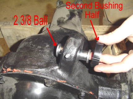
Fifth, place the supplied ball joint washers on either both sides of the ball joint bushings. Using the supplied #10-32 x 2.00” bolts and #10-32 nylok nuts clamp the entire assembly in place. Torque the #10-32 bolts to 25 to 30 inch pounds. Cut off any extra bolt length that extends past the nut.
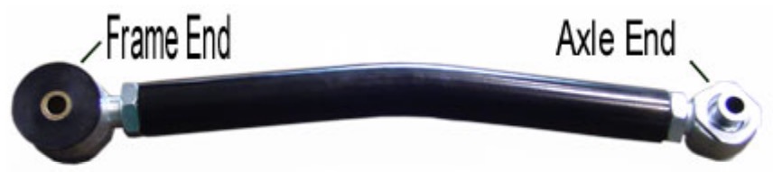
17. Install the supplied front upper control arm. Set the control arm to the specified length for your given lift height from the tables on page 4 or page 5. The Krawler Joint end (spherical joints) goes into the upper position in the driver’s side long arm mounts and gets secured using the supplied 14mm x 100mm bolt and nylok nut. The clevis end gets mounted at the axle and is secured with the supplied 14mm x 100mm bolt, washers and nylok nuts. Do not allow more than ½” of threads to show past the jam nut for final adjustment. Please note; if you have a Rubicon Model please make sure the clevis bracket has clearance between the mount and your electric locker connection.
18. Install the front lower control arms with Krawler Joint at the axle mount and the Monster Bushing at the new frame mounts. Set the front lowers to the specified length in the control arm table on page 4 or 5 for your given application. Do not allow more than ½” of threads to show past the jam nut for final adjustment. Helpful Hit: While setting the control arm length make sure to balance out the thread showing past each jam nut on the flex joint and the krawler joint. Orient the Krawler Joint for maximum amount of movement, then add red loctite and tighten down the jam nut on the joint prior to installing the arm since it is difficult to get at the jam nut when it is in the vehicle. Remember it is a 1”-14 Jam nut so do not be afraid to over tighten it (In other words put something behind it for God Sakes).
Use the OEM hardware for installation at the axle end and the supplied 14mm x 100mm bolts and nylok nuts for the new frame connection. At the frame the new hardware can be passed through the hole outside the frame right into the arm mounting location so exhaust interference is minimized and disassembly on the trail is a snap if the need were to ever arise.
Also note: The bend in the arms is for improved ground clearance. The orientation of the arm is controlled by locking down the jam nut on the flex joint at the frame connection with the arm oriented as you would like.
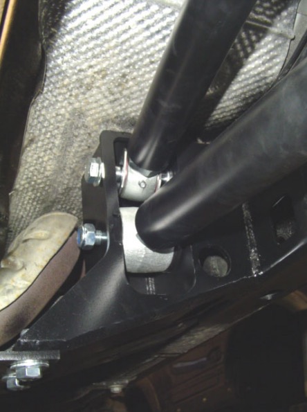
D.S. Frame Connections
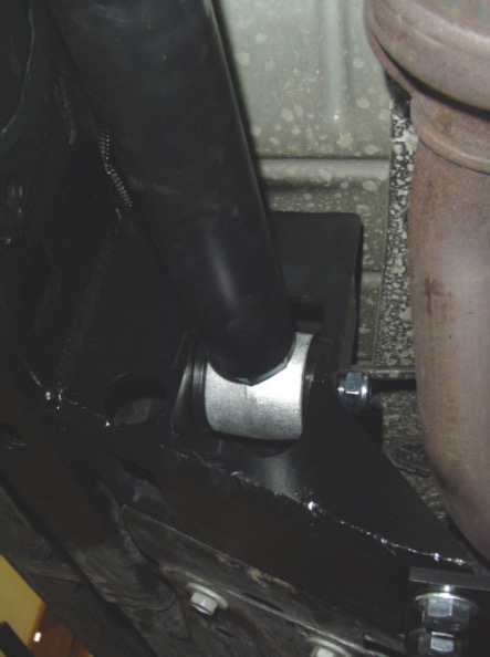
P.S. Frame Connection
19a. For the 3.5” Systems Only (5.5” Systems skip this step). Install the supplied front track bar. Set the track bar to the specified length from the tables on page 4 or 5 for your given application. Balance the amount of thread showing past the jam nuts. Then install the track bar. The bushing end goes at the frame and the heim joint end goes to the axle end. Secure the frame and axle connections with the OEM hardware. Please note the bend in the track bar is for clearance for the differential and the orientation of the track bar is controlled by locking the jam nut of the flex joint at the frame connection. Once the orientation of the bar is set, then orient the heim joint at the axle connection to have maximum amount of movement at the axle and lock the jam nut in place. Using loctite on the jam nuts should prevent them coming loose and damaging the thread integrity of the track bar. Do not allow more than ½” of threads to show past the jam nut for final adjustment.
19b. For the 5.5” Systems Only (3.5” Systems skip this step). Install the supplied front track bar. Set the track bar to the specified length from the tables on page 4 or 5 for your given application. Balance the amount of thread showing past the jam nuts. Then install the track bar. The bushing end goes at the frame and the heim joint end goes to the new mounting hole in the track bar bracket at the axle. Secure the frame connection with the OEM hardware and the axle connection with the supplied 14mm x 60mm bolt, 14mm washers, and 14mm nylok nuts. Please note the bend in the track bar is for clearance for the differential and the orientation of the track bar is controlled by locking the jam nut of the flex joint at the frame connection. Once the orientation of the bar is set, then orient the heim joint at the axle connection to have maximum amount of movement at the axle and lock the jam nut in place. Using loctite on the jam nuts should prevent them coming loose and damaging the thread integrity of the track bar. Do not allow more than ½” of threads to show past the jam nut for final adjustment.
20. Install the Rock Krawler front springs making sure the end of the spring sits properly in the spring buckets on the axle. [Omit this step for coil over kits and see the coil over instructions that follow].
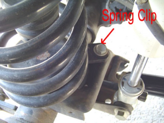
21. Install the supplied front spring retainer clips by placing the clip on the bottom coil, mark the hole in the spring pad and then drill a 10mm hole. Then secure the spring clip with the supplied 10mm x 35 mm bolt and nylok nut. This should prevent your springs from rotating out of the spring pockets on the axle should they experience a no load condition off-road. The Driver’s Side is shown below and the spring clip sits behind the axle as shown. On the Passenger Side it is just the opposite. The spring clip sits on the front side of the axle. [Omit this step for coil over kits and see the coil over instructions that follow].
22. Install the front shocks using original hardware. [Omit this step for coil over kits and see the coil over instructions that follow].
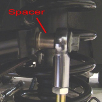
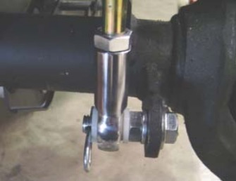
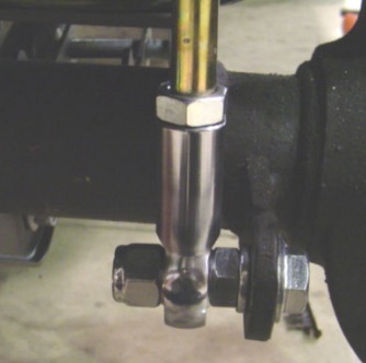
23. Install the front sway bar disconnects as shown below. For the top mount use the supplied ½” x 2.5” bolt, .595” long spacer, and nylok nut to make the connection. Please note the shoulder of the spacer goes against the sway bar itself. For the bottom connection attach the ½” x 2.0” long bolt with cross drilled hole to the factory sway bar link bracket. Secure the bolt with the supplied ½” jam nut. For connecting the bottom end of the sway bar link to the bottom bolt there are two options supplied with each kit. If you do not have the automatic sway bar disconnect feature you can secure the bottom end of the sway bar link with the 2 nylon washers on either side of the rod end and secure it with the pin. If you do have the automatic sway bar disconnect feature you can simply secure the bottom rod end with the supplied ½” nylok nut. Please note: on some sway bars you may have to reem out the hole to ½” with a ½” drill bit.
Top Sway Bar Connection
Bottom Sway Bar w/o Auto Disco
Bottom Sway Bar w/ Auto Disco
24. Disconnect the drag link from the OEM pitman arm and remove the OEM pitman arm from the steering box. Install the supplied pitman arm. Reconnect the drag link to the new pitman arm.
25. Remove the factory front rubber brake lines and install the new stainless steel brake lines. Do not worry about bleeding the brake system at this time since you are going to have to install the new rear lines in a little while. Be sure to add slack to your ABS lines and route them with your new stainless steel lines using two of the supplied zip ties to secure them together.
26. Install front rims and tires and lower front of the vehicle to the ground, check that the front axle is centered under the vehicle. If the axle is not centered, adjust rod end/krawler joints to center the axle. If the axle is centered, tighten all hardware to proper torque spec. Do not allow more than ½” of threads to show past the jam nut for final adjustment.
Coil Over Front Conversion with Comp Kits or Stand Alone Option
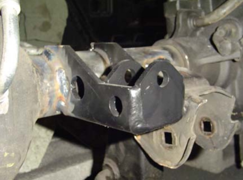
1) Remove the factory coil spring mount and shock mount from the frame as shown below. Prep the frame surface for welding.
Driver’s Side Frame Rail Showing Removal of OEM Spring and Shock Mount
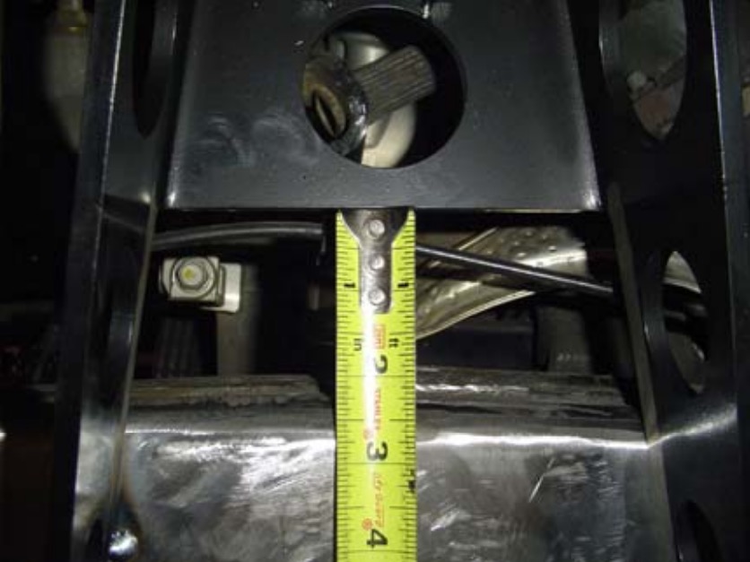
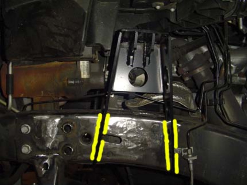
2). Grab a front upper coil over shock mount and position it on the frame as shown below. It tucks nicely inside the pocket in the fender where the OEM shock tower used to go. Position the back edge as shown below 2.5” off the frame. Make sure all surfaces are prepped for welding and all brake lines are clear so they will not get harmed.
Front Upper Coil Over Mount Positioned on the Frame
3) Using a fillet weld technique; weld the legs to the frame using a ¼” fillet weld on each side as shown below. This must be done by a certified welder.
Front Upper Coil Over Shock Mount Welded to the Frame
4) Remove the front lower shock mounts from the axle. Prep the axle for welding on the new lower coil over shock mounts.
5) Grab the new lower coil over shock mount and weld it to the axle again, using a 1/4” fillet weld technique. It is positioned exactly where the OEM lower shock mount was. A good frame of reference is the bottom of the bracket should be horizontal. A certified welder is required. Weld both sides and across the bottom.
Front Lower Coil Over Mount Installed
6) Apply a durable finish of your choice to the brackets, axle, and frame prior to installing the coil over shock assemblies.
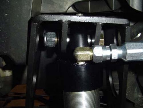
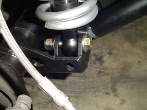
7) Grab the coil over shock assembly. If the front shock is equipped with misalignment spacers be sure to have them on each side of the spherical joint when installing the coil over. If the spacers are integrated into the spherical joint do not worry about it. Simply bolt the coil over into placing using the supplied ½” x 2.75” bolt, washers and nylok nut on both top and bottom as shown below.
Upper Coil Over Mount
Lower Coil Over Mount
8) Adjusting the Coil Overs!
a) For the 5.5” lift the coil overs should be adjusted to have an operating measurement of 24.25” /- 1” from mounting bolt to mounting bolt. This is with all of the weight on the front coil over assembly. Adjust the spanners on the coil overs until your desired vehicle stance and lift is achieved.
Now Lets Start the Rear Assembly
1. Park vehicle on a level, hard working surface. Raise rear of vehicle and support with safety jack stands. Locate jack stands on the frame behind the rear axle.
2. Remove the rear rims and tires.
3. Support the rear axle using a hydraulic floor jack.
4. Remove the rear shocks and save the hardware for reuse.
5. Remove the rear sway bar links.
6. Lower the rear axle and remove the rear coil springs.
7. Remove the rear track bar and discard it, save the hardware for reuse.
8. Remove the rear lower control arms using and save the hardware for reuse.
9. Remove the factory rear upper control arms and discard them, save the hardware for reuse.
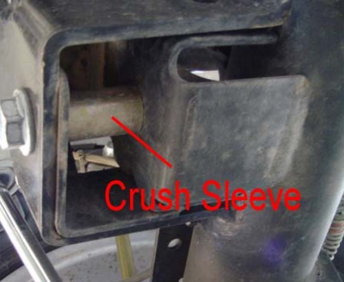
10. Install the rear track bar relocation bracket as shown below. Attach the bracket using the OEM bolt with the supplied 7/8” O.D. x 9/16 I.D. x 1.625” Long crush sleeve on the inside of the OEM lower track bar mount as shown below. Drill a ½” hole through the inside of the factory bracket where the supplied hole in our bracket is and secure that position with the supplied ½” x 1.25” long bolt, washers and nylok nut. Drill a second 10mm hole through the top of the OEM bracket where the existing hole is in out new bracket and secure it with the supplied 10mmx35mm bolt and 10mm nylok nut. Please note: Our bracket wings cup the OEM rear axle tubes. This is due to the fact that the OEM factory rear track bracket is so weak. It is required before your first off-road adventure with your JK that these wings be welded to the axle tubes. This will prevent any failures of the rear track bracket assembly.
11. Perform the following weld on operations;
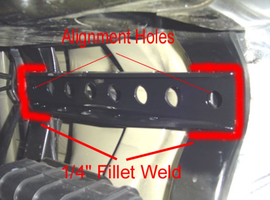
11a) Install the independent third link upper control arm mount. The bracket spans the two rear upper frame cross members and aligns off the holes in each cross member as shown below. Then clamp the bracket with the holes aligned to the cross members and weld it in place. Be sure to properly prep the surfaces and apply a durable finish after the weld operation is completed.
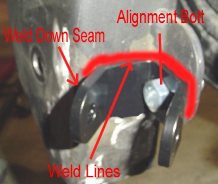
11b) Install the weld on rear cradle. Center the cradle left to right on the axle. Make sure the third link mount on the top is open to the front so the cradle is oriented properly. Then, hold the offset tool as shown below up against the differential cover and rotate the cradle back until it contacts the offset tool. Then weld it in place on front and back as shown below.
Aligning the rear cradle
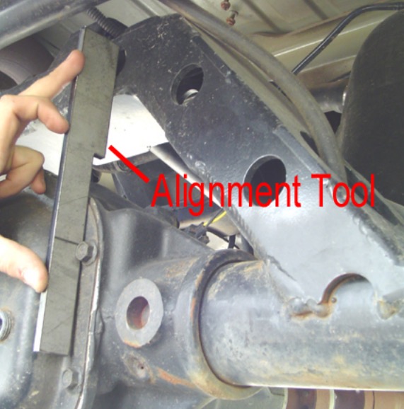
Welding the rear cradle
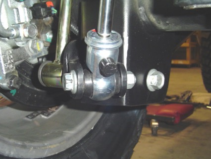
11c) Install the rear shock relocation brackets. The brackets have a hole that aligns them off the rear sway bar link mount as shown below then weld them in place as shown below. Be sure to prep the surfaces properly prior to weld and after the weld operation is completed be sure to apply a durable finish of your choice. Now you can trim off the remaining of the lower control arm mounts that hand below the rear shock relocation bracket.
Installing the Bracket
Final Ground Clearance Improvement
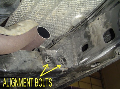
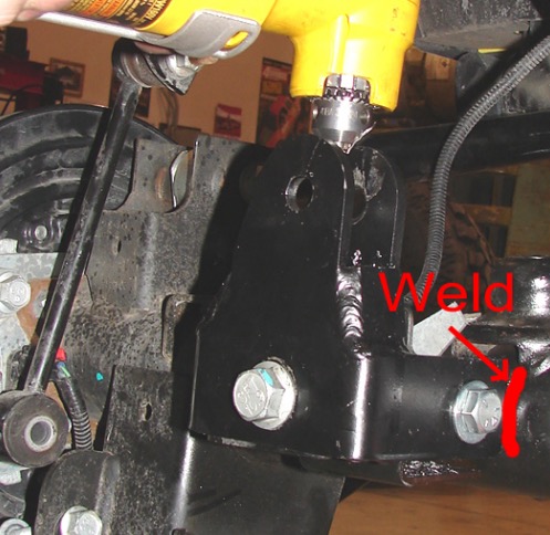
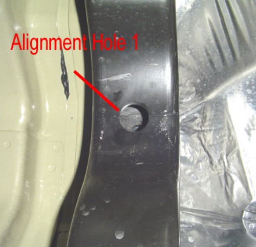
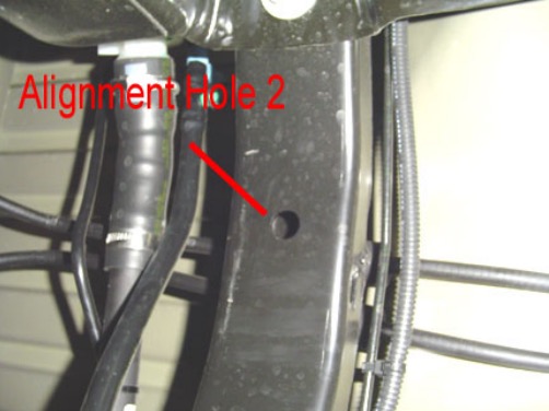
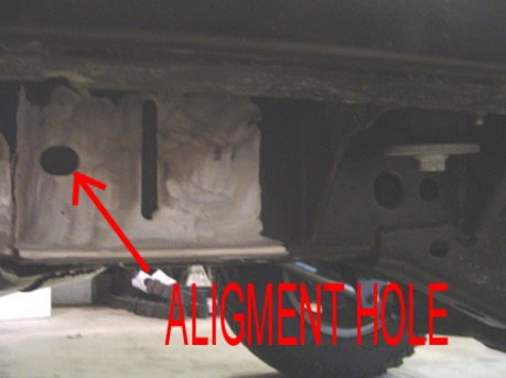
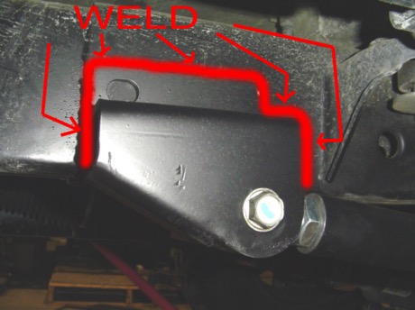
11d) Weld on the rear lower control arm long arm mounts. The mounts locate off the sloted hole in the side of the frame as shown below and require being welded in completely using a ¼” fillet weld as also shown below. Keep the top edge of the mount horizontal when welding in place. Please note there is a driver’s side mount and a passenger’s side mount. The open end of the mount faces reward as shown below. The pictures below are showing the driver’s side only.
Alignment Hole in Side of Frame
Weld on Lower Control Arm Mount
11e) Now is a good time to cut off the OEM lower control arm mounts at the frame. You can also remove the OEM upper mounts from the frame and from the axle to make your installation and vehicle look perfect.
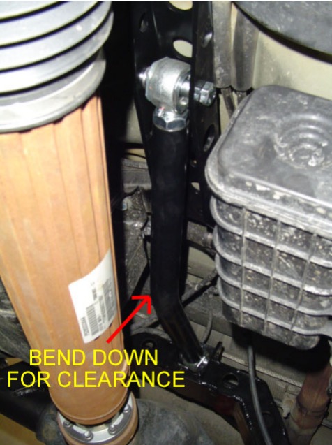
12. For X Factor Plus Systems Only (All other system omit this step) install the rear upper control arm. Set the rear upper control arm to the specified length for the appropriate lift height from the tables on pages 4 and 5. Bolt the rear upper control arm in place using the supplied 14mm x 90mm bolts, washers, and nylok nuts. The rear cradle has adjustable anti-squat holes built into it. For all long arm kits it is recommended that you start out on the middle hole in the cradle, then adjust to your liking and driving style. Please note: Tightening the jam nut for the frame connection is difficult when the arm is in the vehicle. It is recommended that this jam nut be loctited and tightened outside the vehicle. Please note: the arm has a bend in it. The bend is to go down to allow for greater up travel of the suspension before interference issues can occur.
13. Install the rear lower control arms with Krawler Joint at the axle mount using the OEM hardware and the Monster Bushing at the new long arm mounts using the supplied 14mm x 100mm bolts and nylok nuts. Set the rear lowers to the specified length in the control arm table on page 4 or 5 for your given application. Do not allow more than ½” of threads to show past the jam nut for final adjustment. Helpful Hit: While setting the control arm length make sure to balance out the thread showing past each jam nut on the flex joint and the krawler joint. Orient the Krawler Joint for maximum amount of movement, then add red loctite and tighten down the jam nut on the joint prior to installing the arm since it is difficult to get at the jam nut when it is in the vehicle. Remember it is a 1”-14 Jam nut so do not be afraid to over tighten it (In other words put something behind it for God Sakes).
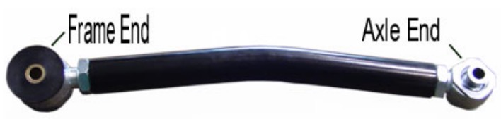
Also note: The bend in the arms is for improved ground clearance. The orientation of the arm is controlled by locking down the jam nut on the flex joint at the frame connection with the arm oriented as you would like. See below for proper orientation.
15. Install the supplied rear track bar. Set the track bar to the specified length from the tables on page 4 or 5 for your given application. Balance the amount of thread showing past the jam nuts. Then install the track bar. The bushing end goes at the frame and the heim joint end goes to the new mounting hole in the track bar bracket at the axle. Secure the frame connection with the OEM hardware and the axle connection with the supplied 14mm x 60mm bolt, 14mm washers, and 14mm nylok nuts. Please note the bend in the track bar is for clearance for the differential and the orientation of the track bar is controlled by locking the jam nut of the flex joint at the frame connection. Once the orientation of the bar is set, then orient the heim joint at the axle connection to have maximum amount of movement at the axle and lock the jam nut in place. Using loctite on the jam nuts should prevent them coming loose and damaging the thread integrity of the track bar. Do not allow more than ½” of threads to show past the jam nut for final adjustment.
16. Install the Rock Krawler rear coil springs.
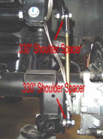
17. Install the supplied Rock Krawler rear sway bar links. Install the supplied rear sway bar links using the supplied ½” x 2.0” bolts, .330” long shoulder spacers and ½” nylok nuts as shown below. Please note the shoulder of the spacer goes towards the sway bar and the bottom mounting bracket (away from the rod end).
18. Remove the factory rear brake lines and install the supplied stainless steel brake lines. Now you can go ahead and blead the brake system per the JK service manual.
19. Remove the wire hanger for the rear emergency brake cable and route them to have as much slack as possible.
20. Install the rear shocks. Shocks should be non-expanded can shocks with a shock body of no more than 2” in diameter or there is a risk of the rear shock contacting the rear track bar relocation bracket.
21. Install rear rims and tires, raise vehicle off jack stands and lower vehicle to the ground.
Before Hitting the Pavement or the Trails be sure to make sure the control arms are oriented properly, all spherical joints (heim joints and Krawler Joints) are oriented correctly to allow for maximum movement without bind, and all Jam Nuts are Tight. Make sure the axles are properly centered, pinion angles are correct, there is proper slack in ABS lines, all lines are properly routed so you never run into an issue on or off the road. Go back over all your hardware and make sure each connection is tight and follow the following torque specs;
Torque all 14mm and 9/16 bolts to 90-100 ft-lbs. Torque all 12mm and ½ bolts to 75-80 ft-lbs. Torque all 10mm and 3/8 bolts to 30-35 ft-lbs.
Please note: If your steering wheel is off at all the ESP will be activated. This will be corrected once the vehicle is aligned by a certified Jeep dealership.
A note about jam nuts and the consumer's responsibility. The installer is the person or persons initially responsible for the proper setup of the suspension system and/or components and the initial tightening of the jam nuts. The consumer or vehicle owner is the person or persons responsible for maintaining the jam nuts tight. Failure to do so will result in the rapid deterioration of the threads in the control arm and will impose a "cause for concern" for the occupants of the vehicle. Failure to comply with the warnings headed in the directions regarding the amount of threads showing past the jam nut will also cause the same "cause for concern" for the occupants of the vehicle. All of the above items are the responsibility of the vehicle owner and or installer. If a threaded section of a component is bad it will show itself defective immediately. Threads that fail over time are due to improper maintenance of jam nuts and can be proven very easily. Thread sections not properly maintained or setup are not covered under warranty. This is the end user and installer's responsibility.
It is a requirement that your vehicle be taken to a Jeep Dealership for an alignment. The Jeep Dealer should align the vehicle and also verify all ESP/ABS connections are in good working order or trouble may arise. The routing of ABS/ESP and Brake Lines is your responsibility. Do so carefully.
Good Job. Your installation is complete. Now go out and enjoy your vehicle.
Rear Stretch Additional Requirements
First off, if you are willing to go this far as to stretch your JK 2 Door, Rock Krawler Suspension is proud of you. You are about to experience one of the best things you could ever do to improve the off road ability of your JK.