 FREE 1 to 3-Day Delivery on Orders $149+ Details

How to Install Rock Krawler 3.5 in. X-Factor Coil-Over Long Arm Suspension Lift Kit w/ 4 in. Stretch - Stage 2 (04-06 Wrangler TJ Unlimited) on your Jeep Wrangler
Dear customer: Thank you for purchasing the best system on the market for your TJ/LJ. We are sure you will be happy with this system after your installation is complete. Please take your time during the installation and be sure to do it correctly. Completely read the directions before starting your installation so you know what to expect. Remember, your personal safety depends on it. Should you have any questions during this installation feel free to give our tech line a call (518-270-9822) and we will be happy to help you.
Note: BE SURE TO CHECK ALL FASTENERS FOR PROPER TORQUE BEFORE TEST DRIVE. RECHECK AFTER 500 MILES AND BE SURE TO CHECK PERIODICALLY.
Warning: Read and understand all instructions, warnings and safety precautions in these instructions and your owner’s manual before attempting to install these components.
Warning: Rock Krawler Suspension Inc. does not condone or authorize the use of any other suspension components with its products. Should Rock Krawler Systems or components be installed in junction with other products or not per the provided instructions Rock Krawler Suspension Inc.’s warranty is void and is not to be held accountable for any resulting actions.
Caution: Proper installation of Rock Krawler Suspension, Inc. Products requires knowledge of recommended procedures for disassembly/assembly of OE vehicles and components. Access to OE shop manuals and special tools are required.
Attempting to install this kit without knowledge of these procedures may affect the safety of your vehicle and or the performance of these components. Rock Krawler Suspension, Inc. strongly recommends that this system be installed by a certified mechanic with off road experience.
Warning: Rock Krawler Suspension, Inc. does not recommend combined use of suspension lifts, body lifts or other lift devices. Combined use of lifts may result in unsafe and unexpected handling characteristics. Also, many states now have laws restricting vehicle lift, bumper heights and other alterations. Consult local laws to determine if your proposed alterations (including installation of this system) comply with your state laws.
Caution: Rock Krawler Suspension Inc. recommends the use of locktite on all hardware, unless noted otherwise.
Warning: Properly block and secure vehicle prior to installation.
Warning: Always wear safety glasses when using power tools
Warning: The use of limiting straps is recommended to avoid possible damage from over extending the suspension of your vehicle.
Helpful hint:
Do not tighten connections until assemblies are installed in entirety.
Reference Lengths:
TJ/LJ 2.5” Front Track Bar Assembled Length – 32 1/8”
TJ/LJ 3.5” Front Track Bar Assembled Length = 32 1/2”
TJ/LJ 5.5” - 7.0” Front Track Bar Assembled Length = 33 3/8”
TJ/LJ Front Lower Control Arm Assembled Length = 40”
Front Upper Arm Assembled Length = 42 13/16”
TJ Rear Lower Control Arm Assembled Length = 29 5/16”
TJ Triangulated 4 Link Assembled Length = 33 3/4”
LJ Rear Lower Control Arm Assembled Length = 39 3/16”
LJ Triangulated 4 Link Assembled Length = 43 3/8”
LJ 4” STRETCH Rear Lower Control Arm Assembled Length= 43 3/16”
LJ 4” STRETCH Triangulated 4 Link Assembled Length = 47 1/2”
TJ 5” STRETCH Rear Lower Control Arm Assembled Length= 33”
TJ 5” STRETCH Triangulated 4 Link Assembled Length = 38”
TJ 8” STRETCH Rear Lower Control Arm Assembled Length= 39 3/16”
TJ 8” STRETCH Triangulated 4 Link Assembled Length = 43 3/8”
Please Note: All Control Arms, Torque Arms, Track Bars and Triangulated 4 -Link Assemblies come pre-assembled, but they require final adjustment as specified above in the directions above.
Driving Tips:
1) For Rock Crawling it is best to have the front sway bar disconnected. This will allow your suspension to do its intended function. Our suspension will give your vehicle unmatched articulation which will give you traction to keep your vehicle moving. Let the system do the work. This will save on vehicle abuse.
2) For Mud, especially sloppy mud, it is best to have the front sway bar connected. This will limit the suspension travel which is better for mud.
3) For Highway driving it is best to have the front sway bar connected. This will give you the on highway ride and handling characteristics you expect. If you choose otherwise, you do so at your own risk.
Start with the middle of the Vehicle
1. Park vehicle on a level hard working surface and block the front wheels so the vehicle cannot move.
2. If you have a 2003 or newer Wrangler with the automatic skid plate, please remove it. It will simply be in the way for the movement of the front driveshaft at your new lift height.
3. You do not need to jack up the vehicle for the first part. We will be putting in your new skid plate center section and control arm mounts.
4. Support the transmission and transfer case so the OEM skid plate / belly pan can be completely removed. Remove the skid plate and discard it. Save the OEM hardware for alignment purposes and reuse. For Rubicon models also disconnect your air pump from the skid plate and tie it up. It will be reattached to the new center skid plate member.
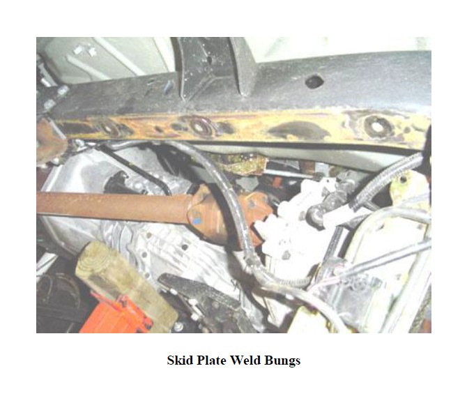
5. Grind down the weld bungs in the frame so they are almost flush with the frame. This is required since our skid plates grab the frame by the top and the bottom which adds a tremendous amount of structure to your frame. See the picture below for further details.
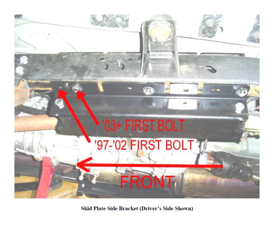
6. Grab the driver’s side frame rail section and get ready to put it in place. The driver’s side bracket contains the front upper control arm mount and lower control arm mount welded to it. The passenger side mount only has the rear upper control arm mount welded to it. Install the bracket as shown below. Please note; on the 97-02 model year TJ’s the most forward hole in the new bracket lines up with the front OEM skid plate bolt hole, on the -03 and newer models the first OEM skid plate bolt goes in the second hole in the new bracket. Please see picture below. Perform the same operation with the passenger side. All the brake lines and fuel lines will stay attached to the frame. On Rubicon models, please reroute the front locker lines on the inside of new frame rail brackets.
7. There are two ways to firmly attach these brackets to the frame. Weld it or bolt it.
If you are going to weld it in place, then bolt it up tight to the frame using the OEM skid plate bolts. Then, fully weld them in place along the front and rear leading edges and then down the side of brackets. Be sure to weld both on top and on the bottom of the frame. This will give you the most amount of structure. Please note to prep the surfaces for weld prior to performing that operation.
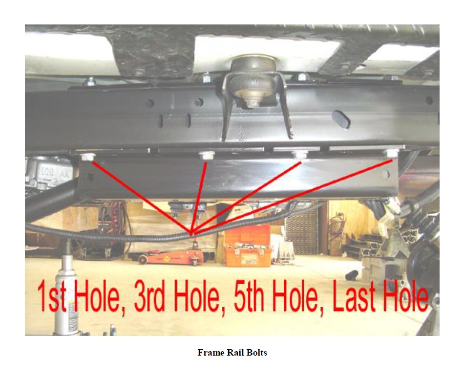
The second method is to bolt it in place. This is more cumbersome than welding, but still just as effective. In the first, third, fifth, and last holes in the frame rails, center punch the holes and drill up vertical through the fame with a ½” drill bit. Please note you will have to drill up through the top plate as well. This is because we know the likely hood of someone drilling vertical up through the frame and hitting a ½” hole in the top plate is very slim on all the holes. This is a much more sure fire way to make it happen. Once the holes are drilled simply place a ½” x 5.5” bolt and washer up through the drilled hole and secure it with the supplied nylok nut. No washer is needed on the topside of the bracket. You should have (4) bolts holding the brackets in. Torque them to 60 foot pounds. See the picture below. Perform the same operation on the passenger’s side. Please note: For the forward bolts you may have to dimple the floor pan (which really isn’t hard) to gain clearance for the top of the bolt and the nut.
Please note: you will have to heat up the support bracket for the catalytic converter to move it as close to the T-Case as possible so it does not contact the new bracket.
If you have long rear upper control arms, now is a very good time to remove the OEM Cat Back Exhaust.
8. Now that the frame rails are in, we can now locate the center skid plate. Grab the center skid plate. Bring it up into position and attach it to the frame rails using the supplied (12) ½” x 1.25” carriage bolts (smooth head) and the (12) supplied spiral lock washers and (12) ½-13 jam nuts. Then lower your t-case and transmission into place and attach it to the center skid using the OEM supplied hardware.
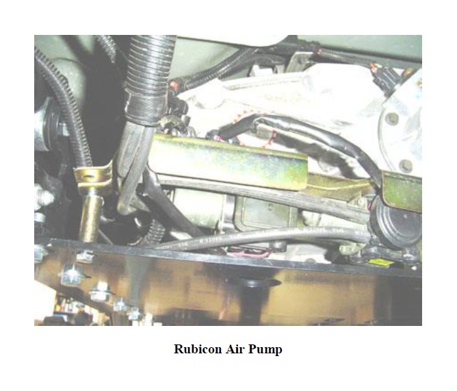
For Rubicon Models only, perform the following; Reattach the air pump assembly to the center skid using 3 of the four holes provided. See picture below for visual aids. Attach the air pump with the supplied (2) 5/16 x 1 bolts and nylok nuts, then on the offset side, attach with the 5/16 x 2.5 bolt, nylok nut and 5/8” O.D. by 10mm I.D. x 1.625 Tubular Spacer.
9. Now that your center section is complete, we can begin performing the disassembly and reassembly of your vehicle.
Let’s move to the Front End
1. Make sure the vehicle is still on a level hard working surface and block the rear wheels so the vehicle cannot move. Make sure the emergency brake is applied. Raise the front of vehicle and support with safety jack stands. Locate jack stands on the frame as far forward as possible.
2. Remove front rims and tires.
3. Support the front axle housing using a hydraulic floor jack.
4. Remove front shocks using 15mm box wrench for the top and 13mm socket with ratchet in combination with 13mm box wrench on the lower bolts. Keep original hardware to install new shocks.
5. Remove front sway bar links form upper location using 15mm box wrench. It may be helpful to use a hammer to push up against then end of the sway bar while pulling down on the old links to release.
6. Remove and replace front brake lines; following provided instructions in brake line kit.
7. Remove front track bar by using a T-55 torx bit on the lower axle mount then pull the cotter pin from the top castle nut and remove castle nut. It will be necessary to use a pickle fork (ball joint separator) to remove the top rod end from its mount. Discard the OEM track bar and castle nut for they will not be reused.
8. Remove front spring retainer clip(s). Keep original hardware and clips to reuse on final assembly.
9. Remove the OEM front upper control arms, and discard them.
10. Lower the front axle assembly and remove front springs.
11. Remove the OEM front lower control arms using 13/16 wrench and 13/16 socket with ratchet and save the hardware for reuse. Discard the OEM lower control arms. You must remove your OEM lower control arm mounts from the frame to allow for proper suspension travel. You can also remove the front upper control arm mount off the axle on the passenger’s side if you so desire. This will make your vehicle look cleaner.
12. For the Coil Over Kit Front Ends Only; Remove the OEM shock and spring tower from the frame and put in place the new coil over shock tower as shown below.
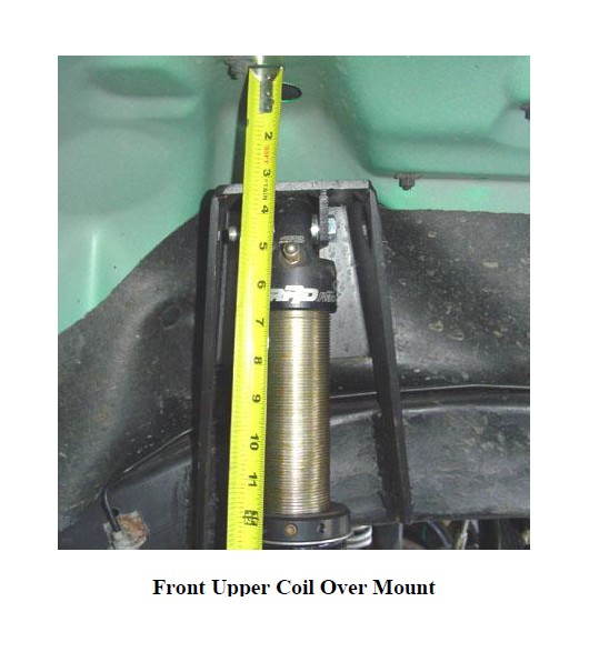
Weld the front upper shock tower to the frame as show. Weld both sides of each leg down the frame. Trim any excess that hangs down from the frame. The distance the top of the tower should be from the bottom of the inside of the fender is 3.25” as shown above. For aid in alignment, there is a hole in the top of the tower. This hole should be directly below the shock hole in the fender.
Mount the front lower coil over mounting brackets as shown below.
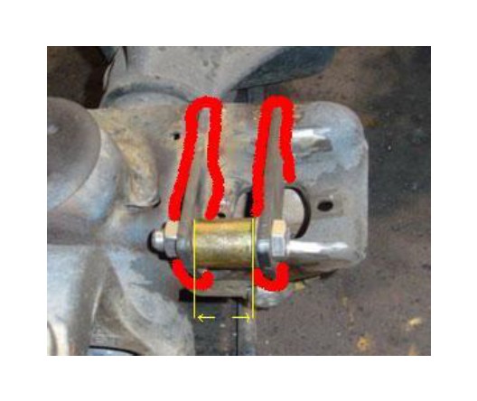
Place the bracket with the shorter leg towards the front of the OEM shock bracket as shown and fully ¼” fillet weld the bracket in place on both sides. Next, take the bracket with the longer leg and space it 1.25” from the front bracket and fully ¼” fillet weld it in place making sure the holes line up and you can pass a ½” bolt through the holes.
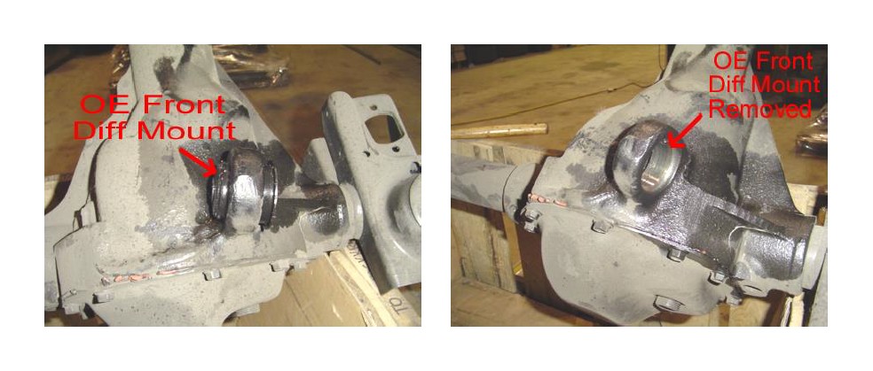
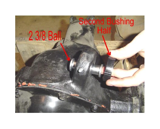
13. Now it is time to make the stock front upper control arm mount on the driver’s side into a re-build-able, flexible joint.
First, pound out the driver’s side OEM front upper control arm bushing and sleeve. Note: It is easier if you hit on the steel sleeve. If you run into trouble drill out the rubber bushing material and then remove the entire assembly.
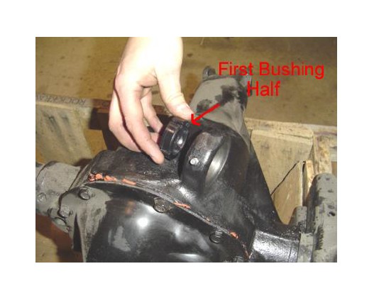
Second, take one of the supplied ball joint bushings and push it in one side. Note: make sure the slots for the fasteners are on top and bottom for correct orientation. If you want to pack it with marine grade grease, now is the time to do so!
Third, place the supplied chrome plated ball inside the bushing and retain it in place with the other supplied Ball Joint bushings on the other side and push it in. Make sure the ball is oriented so that a bolt can pass through it before going to the next step.
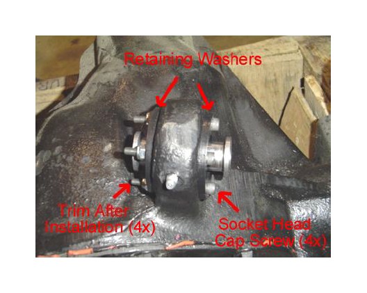
Fourth, place the supplied ball joint washers on either both sides of the ball joint bushings. Using the supplied #10- 32 x 2.00” bolts and #10-32 nylok nuts clamp the entire assembly in place. Torque the #10-32 bolts to 25 to 30 inch pounds. Cut off any extra bolt length that extends past the nut. If you want to you should be able to tighten the flanges to a point where they come in contact with the housing. This is the most secure method. Just be sure to torque down the bolts evenly.
14. Remove the OEM front upper mount off the passenger side of the front axle for it will not be removed. Please note; for Triple Threat Systems you will want to mark its location and orientation to put on the new heavy duty front upper mount!
15. For Triple Threat Systems only (All X Factor Systems Please Omit this Step). Note: Before putting in the pass. side front upper control arm you may have to reroute the entire exhaust from the manifold back to allow clearance for the pass. Side front upper control arm to operate.
Place the new Heavy Duty Axle Mount on the passenger side of the axle tube in the exact location and orientation as was the OEM passenger side front upper mount as shown below. Then weld it in place using a ¼” fillet weld all the way around its contact points with the axle tube as shown below.
After the mount is welded in place, then add on the two gussets to give it lateral support as shown below.
Notes: If you do not feel comfident marking the location and welding it in place here is an alternate method!
Simply complete the installation of the entire suspension system as if it was an X Factor System using only the three link front end. Make sure your caster is set properly and the front axle is square in the vehicle! The put in the passenger side front upper arm set to length as specified in the tables at the beginning of the directions. Put the Build A Ball Assembly in the new front upper mount softly (i.e. do not fully tighten everything down for you will want to take the bushing back out prior to welding it in place). Then, bolt the upper control arm in place and attach the new mount with the Build A Ball assembly to the upper control arm. Make sure the Build A Ball joint is as neutral as possible and place the mount on the axle. Then tack weld it in place. Remove the Build A Ball Joint and complete the welding sequence from above.
Apply a finish of your choice, like paint!
Then follow the steps in Step 13 for the Build A Ball joint in the passenger side of the axle mount. Now you have the beefiest passenger side axle mount available anywhere.
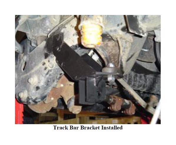
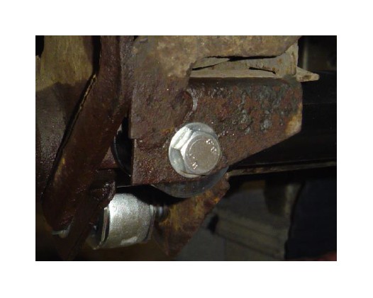
14. Install the track bar bracket as shown below. Bolt the bracket to the stock cast iron bracket with the supplied ½” x 1.75” long bolt and nylok nut and tighten it to draw the bracket up tight. Once the bracket is tight, drill through the frame by center punching the holes and drilling through the frame with a ½” drill bit and mounting the bracket with the (2) supplied ½” x 4.0” long bolts and nylok nuts.
15. Remove the OEM front Lower Control Arm mounts from the frame. Please note; some sort of metal removing tool will be required to perform this operation.
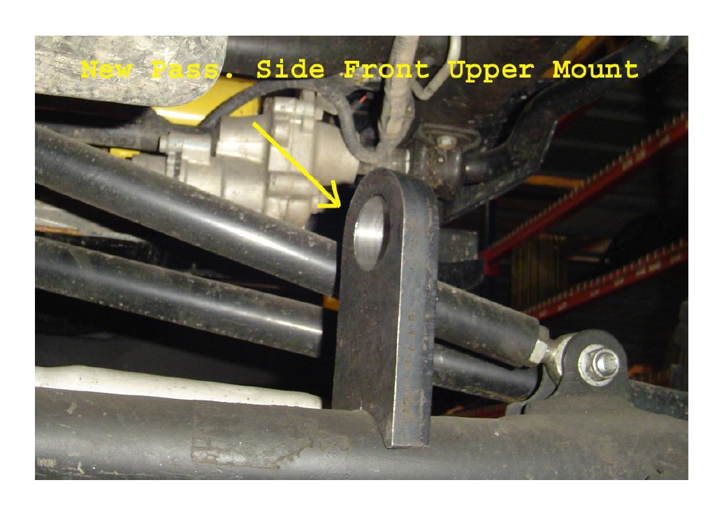
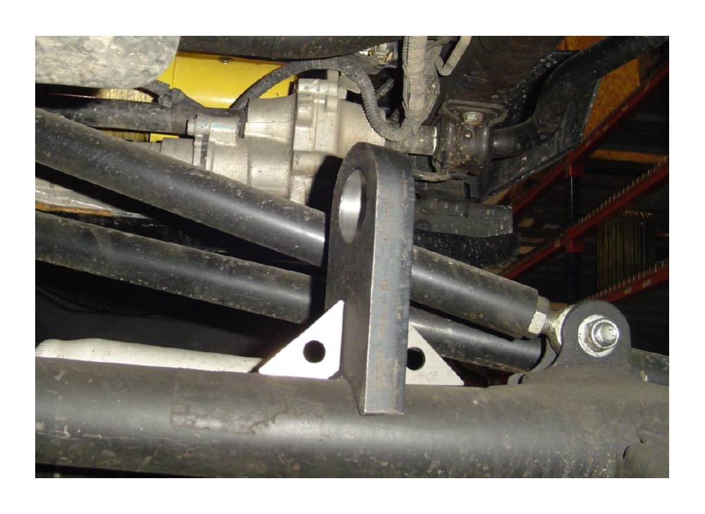
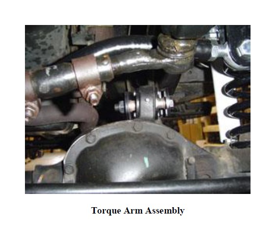
16. Install the front upper arm(s) as shown below. Use the supplied 14 mm x 100mm bolt to secure the Krawler Joint into the skid plate mount on the frame. Please note the nut for this connection is welded into the skid plate assembly. Use the supplied 14mm x 100mm bolt and 14mm nylok nut to attach the clevis end of the front upper arm to the new diff. mount. Make sure the torque arm is installed in the proper orientation. The angle in the clevis brackets will allow the arm to point straight back.
17. Install Rock Krawler lower control arms with one Krawler Joint (Spherical Joint) at the axle mount and the Bushing End to the new lower control arm mounting bracket in the skid plate. Be sure to set the assembled dimension to that specified above. Install the skid plate mount end first, then do the axle end. Attach the Krawler Joints using the original hardware at the axle. Please note: You may want to tighten the lock nut at the axle connection prior to installing the arm since it is hard to get to because of the factory brackets. For the front end there is a specific driver’s side and passenger’s side. From the frame end (bushing end), the arm bends out towards the axle mount and then down. Once the arm is in place, orient the joint to have maximum misalignment. Then lock the jam nuts. Make sure all jam nuts stay tight. Loctite may be required. Do not allow more than 5/8” of threads to show past the jam nut for final adjustment.
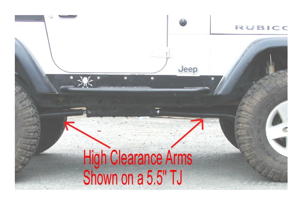
Note: The Lower Control Arms are bent for improved ground clearance as shown below.
18. Drill out the lower track bar mounting hole at the axle to 9/16. Install the Rock Krawler Adjustable Track Bar using the supplied 14mm x 70mm bolt, nylok nut and washers through the new track bar bracket and the mounting position at the axle.
19. Install the supplied front track bar. Set the dimension to that prior specified center to center for your given application. Use the supplied 14mm x 70mm bolt and nylok nut for the lower axle connection. Use the supplied 14mm x 70mm bolt and nylok nut to connect the track bar to the track bar bracket. Do not allow more than ½” of threads to show past the jam nut for final adjustment.
20. For non-coil over kits install the Rock Krawler front springs and reattach retaining clips. Please note: If your vehicle does not have spring retainer clips or they are damaged please purchase them from your local Jeep Dealer. This will ensure you that the front coils do not fall out prematurely. For LJ Owners we have also included a ¾” front coil spring spacer that can be used on top of our 3.5” coils to remove further rake from your LJ if you so choose.
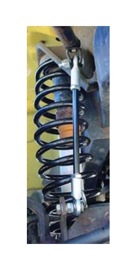
For Coil Over Kits, put in the front coil over assembly with the Schrader Valve towards the top using the supplied ½” x 2.75” long bolts and nylok nuts. Tune the front coil overs to show 4.0 - 4.5” of compression. This is best for rock crawling applications.
Adjusting the Coil Overs!
a) For the 7.0” lift the coil overs should be adjusted to have an operating measurement of 24.25” /- 1” from mounting bolt to mounting bolt. This is with all of the weight on the front coil over assembly. Adjust the spanners on the coil overs until your desired vehicle stance and lift is achieved.
b) For the 5.5” lift the coil overs should be adjusted to have an operating measurement of 22.50 /- 1” from mounting bolt to mounting bolt. This is with all of the weight on the front coil over assembly. Adjust the spanners on the coil overs until your desired vehicle stance and lift is achieved.
21. For non-coil over kits install the front shocks using original hardware. For the 7.0” systems it is highly recommended that you install a high quality bar pin eliminator to transition the shock travel for larger tire sizes and to support the greater un-sprung weight of a larger tire.
22. On the top, connect the sway bar link assembly to the sway bar using the supplied 3/8-16UNCx 1.50 long bolt, 3/8-16UNC lock nut and 3/8”washer. On the bottom, tighten the supplied bolt to the OEM mounting bracket with the supplied special bolt with the jam nut and spiral lock washer as shown. Then connect the sway bar link assembly to the special bolt with a supplied ½ nylon washer on each side of the Rod End and then secure it with the hair pin as shown. Make sure you have 5/8” of thread engagement at a minimum for your rod ends.
23. Install front wheels and tires and lower front of the vehicle to the ground, check that the front axle is centered under the vehicle. If the axle is not centered, adjust the Rod End on Track Bar to center the axle. If the axle is centered, tighten all hardware to proper torque spec. Do not allow more than ½” of threads to show past the jam nut.
24. Disconnect the drag link from the pitman arm. Remove the OEM Drop Pitman Arm and install the newly supplied drop pitman arm. Reconnect the drag link to the pitman arm. Now your front end is complete.
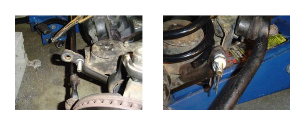
Please note: If you have one of the Wranglers where the ball joint will hit the passenger side sway bar link mount, you can either purchase The Rock Krawler Heavy Duty X Factor Plus Steering Upgrade for $399 or you can do the following;
Drill a half inch hole as shown below. Then install the sway bar link mounting bolts to the outside of the vehicle as shown and remove the remaining material with a metal cutting device. You may have to bend the sheet metal clevis brackets to make sure everything lines up well and the disconnects are easy to remove.
Now Lets Start the Rear Assembly
1. Park vehicle on a level, hard working surface. Raise rear of vehicle and support with safety jack stands. Locate jack stands on the frame as far back as possible.
2. Remove rear Rims and Tires.
3. Support rear axle using a hydraulic floor jack.
4. Remove rear shock bolts using 18mm box wrench and a 15mm socket with ratchet. Keep shock bolts for new shock installation.
5. Remove upper shock retaining bolts using 13mm socket with ratchet; keep stock bolts for new shock installation.
6. Remove rear sway bar link, upper bolts use 18mm socket. Lower nuts and bolts use 15mm socket with ratchet and 18mm wrench. Retain hardware for new rear sway bay link installation.
7. Remove OEM rear lower control arms using 13/16 socket with ratchet and a 13/16 box wrench and save the hardware for reuse. You must remove your OEM lower control arm mounts from the frame to allow for proper suspension travel.
8. Disconnect rear brake lines from rear upper control arms.
9. Remove upper control arms using 15mm socket with ratchet. Retain hardware for installation of Rock Krawler Triangulated 4 -Link Assembly.
10. Remove rear track bar using the T-55 torx bit for the lower mount and 18mm wrench and 18mm socket with ratchet. This can be discarded since it is not going to be reused.
11. Lower rear axle using a hydraulic jack until rear springs can be easily removed.
12. Remove rear springs.
13. FOR STRETCH KITS ONLY;
5” STRETCH SYSTEM
Mount the new spring pad and bump stop as shown below. First you need to remove the following from the frame; track bar bracket and the OEM rear upper spring mounts. This is a bit tricky so be careful.
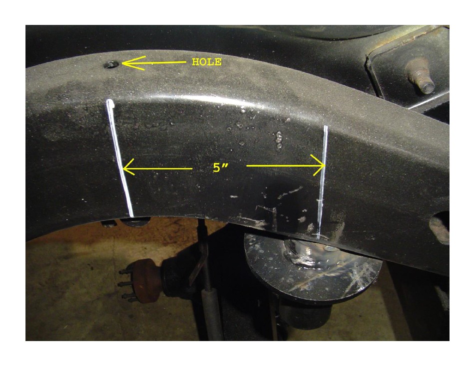
a) Locate the new spring pad stud/bump stop holder either 5.0” back from the center of the arc as shown above. Then fully fillet weld the spring pad stud/bump stop holder in place.
b) Then weld the spring pad plate to the spring pad stud and the frame as shown above. This is where the spring will rest.
c) Once it is all cooled, apply a durable finish of your choice. Then you can thread in the adjustable bump stop. Now is also a good time to install the new spring isolators. They are 3/4” thick poly spring pads that will sit on top of the coil to ensure a nice quiet ride.
d) If you are intending to keep the rear sway bar, we have provided tabs that can be welded to the bottom of the frame as shown above to mount the upper end of the sway bar link. The tab locates at the center of the arc of the frame as shown above.
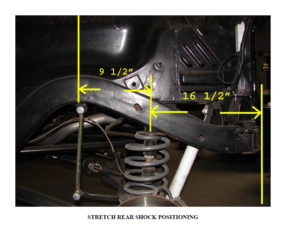
FULL STRETCH SYSTEM
Mount the new spring pad and bump stop as shown below. First you need to remove the following from the frame; track bar bracket and the OEM rear upper spring mounts. This is a bit tricky so be careful.
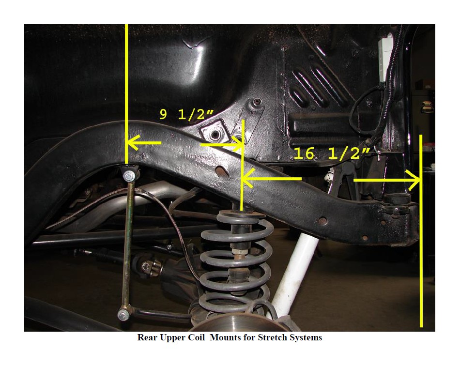
e) Locate the new spring pad stud/bump stop holder either 9.5” back from the center of the arc of the rear frame section or 16.5” forward from the end of the frame as shown above. Then fully fillet weld the spring pad stud/bump stop holder in place.
f) Then weld the spring pad plate to the spring pad stud and the frame as shown above. This is where the spring will rest.
g) Once it is all cooled, apply a durable finish of your choice. Then you can thread in the adjustable bump stop. Now is also a good time to install the new spring isolators. They are 3/4” thick poly spring pads that will sit on top of the coil to ensure a nice quiet ride.
h) If you are intending to keep the rear sway bar, we have provided tabs that can be welded to the bottom of the frame as shown above to mount the upper end of the sway bar link. The tab locates at the center of the arc of the frame as shown above.
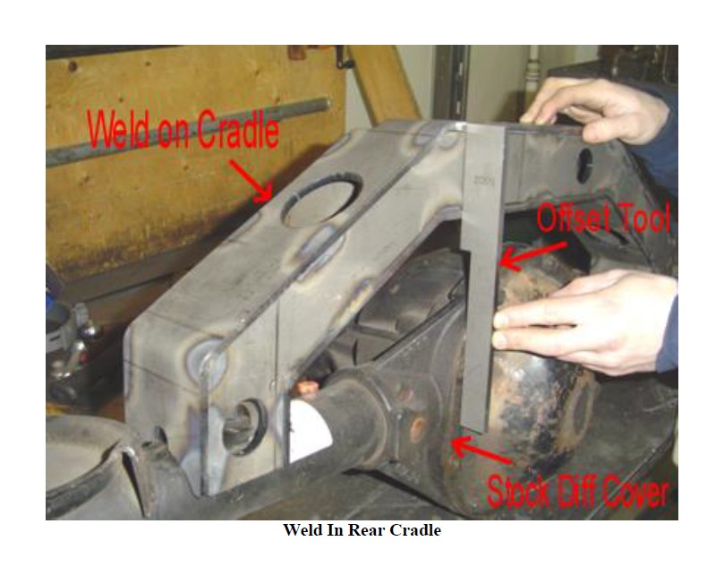
14. Remove the OEM rear upper control arm mounts and the OEM rear track bar mount flush from the rear axle. Install the new weld on cradle to axle. For Dana 35/44/60, Chrysler 8.25 and Ford 8.8 rear axles with the OEM differential cover only, center the cradle side to side on the rear axle housing. Using the supplied offset tool, place the thinner edge of the offset tool flat against the differential cover with the two of the diff. cover bolts removed. Rotate the cradle back until the back flat surface of the cradle contacts the thicker portion of the offset tool as shown below. Now the cradle is in position. Fully seam weld the cradle to the axle tubes. Once completed the offset tool is no longer needed. Replace the two bolts in your differential cover and apply a durable finish to the rear cradle of your choice. Please note: Stock differential cover thicknesses range from 1/8 to 3/16 in thickness. If you have a heavy duty cover or something other than stock you will need to account for the thickness variation when positioning the rear cradle.
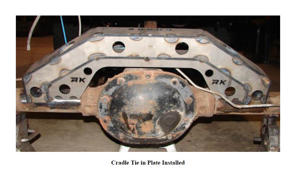
15. Install the weld in cradle tie in plate. This plate makes sure the cradle can not bend and on some applications (Dana 60’s) will allow you to join the tie in plate to the cradle and the axle housing itself. You may need to trim a little off the tie in plate for it to fit properly depending on axle. The tie in plate sits ¼” inside the back surface of the cradle and gets welded to the cradle and the axle, thus calling it a tie in plate. Using a stitch weld technique is acceptable for joining the cradle to the tie in plate, just be sure to cover the corners well. This gives the cradle a nice finished look as well as add strength. Once cooled, apply a durable finish of your choice. See below for an example of what the tie in plate looks like installed.
16. Remove the OEM Lower Control Arm mounts from the frame. Please note; some sort of metal removing tool will be required to perform this operation.
17. For Wranglers with Long Rear Uppers; you will have to disconnect and remove the rear cat back exhaust prior to installing the rear uppers. A custom cat back exhaust will be required for the long rear uppers.
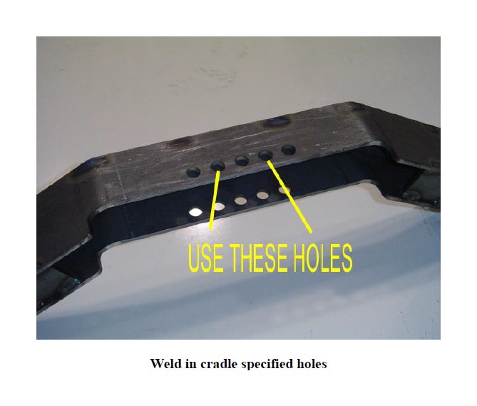
Install the krawler joint (rebuildable spherical joint) end of the rear upper control arm into the new mount into the skid plate with the supplied 14mm x 100 mm bolt, washer, and nylok nut. Install the heim joint end of the rear uppers into the rear cradle into the holes as shown below with the 14mm x 100mm bolts and nylok nuts.
18. Install Rock Krawler lower control arms with one Krawler Joint (Spherical Joint) at the axle mount and the other Monster Bushing at the new lower control arm mounting brackets at the frame. Be sure to set the lower control arms to the assembled length as specified above. Attach using original hardware. Please install the skid plate end first. This will be easiest. Please note: You may want to tighten the lock nut at the axle connection prior to installing the arm since it is hard to get to because of the factory brackets. As was done previously on the front lower control arms, orient the lower Krawler Joint to have maximum misalignment and lock that jam nut. Again loctite may be required to keep the jam nuts tight. Do not allow more than 5/8” of threads to show past the jam nut.
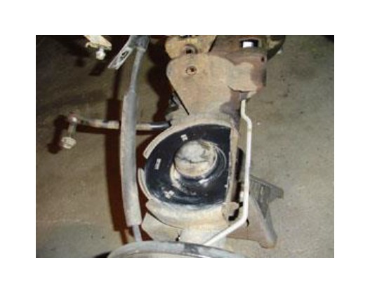
19. Trimming of the rear spring perches for shock body clearance is required unless you use rear shock relocation brackets or shock shifters. Here is a picture of what it should look like.
20. Install Rock Krawler rear springs.
21. Install the shocks of your choice.
For Stretch Kits only; We have provided you with new upper shock mounts for stem loop shocks for the rear. Depending on what type of fuel delivery system you are using will determine the overall placement of these mounts. However, the preferred mounting location is as shown below. Putting the shocks out the back side of the axle and up at a slight angle gives you the maximum amount of control. If you have full width axles you can do even better by out-boarding the rear shocks.
22. Install the Rock Krawler rear sway bar links. Use the original bolts, nuts, and torque to 25 ft-lbs.
23. Install rear brake line and follow instructions contained in brake line package.
24. Install rear rims and tires, raise vehicle off jack stands and lower vehicle to the ground. Check that rear axle is centered under vehicle. If axle is not centered, adjust the Triangulated 4 -Link Assembly, Rod Ends and Flex Joints. Note: Do not allow more than ½” of threads to show past the jam nut. If axle is centered, tighten hardware to torque specs supplied.
Before Hitting the Pavement or the Trails be sure to make sure the control arms are oriented properly, all spherical joints (heim joints and Krawler Joints) are oriented correctly to allow for maximum movement without bind, and all Jam Nuts are Tight.
A note about jam nuts and the consumer's responsibility. The installer is the person or persons initially responsible for the proper setup of the suspension system and/or components and the initial tightening of the jam nuts. The consumer or vehicle owner is the person or persons responsible for maintaining the jam nuts tight. Failure to do so will result in the rapid deterioration of the threads in the control arm and will impose a "cause for concern" for the occupants of the vehicle. Failure to comply with the warnings headed in the directions regarding the amount of threads showing past the jam nut will also cause the same "cause for concern" for the occupants of the vehicle. All of the above items are the responsibility of the vehicle owner and or installer. If a threaded section of a component is bad it will show itself defective immediately. Threads that fail over time are due to improper maintenance of jam nuts and can be proven very easily. Thread sections not properly maintained or setup are not covered under warranty. This is the end user and installer's responsibility.
Servicing of the Rock Krawler Rebuild able Joints is unique from the rest of the industry. We supply our joints with a plug or socket head cap screw in them. Simply remove the plug and put in some 3 in 1 oil which is preferred or WD-40 the reinstall the plug. We do this for many reasons. The first is our joints are extremely tight and will not take grease very easily. Second, in the off-road environment grease attracts much more dirt and debris than it is worth causing joints to wear quickly. Grease would take forever to lubricate our joints since they are so tight. 3 in 1 or WD-40 is clean, simple and lubricates quickly. If worse comes to worse, simply spray down the outside of our joints liberally with WD-40 or MPL and call it a day.
Vehicle should be taken to a certified alignment shop for castor and alignment settings
*Please note; A little more Toe In is beneficial to make larger tires with rough tread track properly.
The required Torque for all 14mm, 9/16 or ½ bolts not explicitly defined is 70 to 80 ft-lbs.
Good Job. Your installation is complete. Now go out and enjoy your vehicle.

