FREE 1 to 3-Day Delivery on Orders $149+ Details

How to Install Rock Krawler 2.5 in. Off-Road Pro Coil-Over Long Arm Suspension Lift Kit - Stage 1 (07-18 Wrangler JK 2 Door) on your Jeep Wrangler
Dear customer: Thank you for purchasing the best system on the market for your Jeep Vehicle. We are sure you will be happy with this system after your installation is complete. Please take your time during the installation and be sure to do it correctly. Completely read the directions before starting your installation so you know what to expect. Remember, your personal safety depends on it. Should you have any questions during this installation feel free to give our tech line a call (518-270-9822) and we will be happy to help you.
Note: BE SURE TO CHECK ALL FASTENERS FOR PROPER TORQUE BEFORE TEST DRIVE. RECHECK AFTER 500 MILES AND BE SURE TO CHECK PERIODICALLY.
WARNING
• Properly block and secure vehicle prior to installation.
• Always wear safety glasses when using power tools.
• Rock Krawler Suspension recommends the use of Loctite on all hardware, unless noted otherwise.
• The use of limiting straps is recommended to avoid possible damage from over extending the suspension of your vehicle.
• Read and understand all instructions, warnings and safety precautions in these instructions and your owner’s manual before attempting to install these components.
• Proper installation of Rock Krawler Suspension products requires knowledge of recommended procedures for disassembly/assembly of OE vehicles and components. Access to OE shop manuals and special tools are required. Attempting to install this kit without knowledge of these procedures may affect the safety of your vehicle and or the performance of these components. Rock Krawler Suspension, Inc. strongly recommends that this system be installed by a certified mechanic with off road experience.
• Rock Krawler Suspension does not recommend combined use of suspension lifts, body lifts or other lift devices. Combined use of lifts may result in unsafe and unexpected handling characteristics. Also, many states now have laws restricting Vehicle lift, bumper heights and other alterations. Consult local laws to determine if your proposed alterations (including installation of this system) comply with your state laws.
• Rock Krawler Suspension does not condone or authorize the use of any other suspension components with its products. Should Rock Krawler Systems or components be installed in junction with other products or not per the provided instructions Rock Krawler Suspension warranty is void and is not to be held accountable for any resulting action
Driving and Handling Tips
• For Highway driving it is best to have the front sway bar connected. This will give you the on highway ride and handling characteristics you expect. If you choose otherwise, you do so at your own risk.
• The ride quality and handling that Rock Krawler is known for is based on using OEM sway bars front and rear with approved shocks. Using any components other than directed can result in adverse handling characteristics and poor ride quality.
• For Off-Road use it is best to have the front sway bar disconnected and the rear sway bar connected. This will allow your suspension to do its intended function. Our suspension will give your vehicle unmatched articulation which will proved traction and feed back to keep your vehicle moving in almost all conditions. Let the suspension do the work!
IMPORTANCE OF JAM NUTS
This is a note about jam nuts and the consumer's responsibility. The installer is the person or persons initially responsible for the proper setup of the suspension system and/or components and the initial tightening of the jam nuts. The jam nuts not only hold the orientation of the joint it is on but it is the single component that puts the necessary pre-load on the joints threads. The consumer or vehicle owner is the person or persons responsible for maintaining the jam nuts tightness. Failure to do so will result in the rapid deterioration of the threads in the control arm and will impose a "cause for concern" for the occupants of the vehicle. Failure to comply with the warnings heeded in the directions regarding the amount of threads showing past the jam nut will also result in the same "cause for concern" for the occupants of the vehicle. All of the above items are the responsibility of the vehicle owner and or installer. If a threaded section of a component is bad it will show itself defective immediately. Threads that fail over time are due to improper maintenance of jam nuts and can be proven very easily. Thread sections and jam nuts not properly maintained or setup, are not covered under warranty. This is the end user and installer's responsibility.
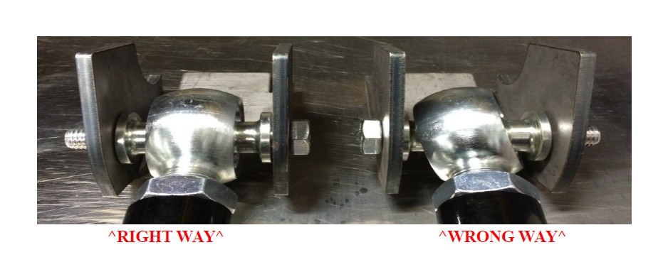
ORIENTATION OF JOINTS
Orient the Krawler Joint for maximum amount of movement with the head of joint perpendicular to bolt / head of the joint vertical in the mounting bracket. This same rule for orientation needs to be followed for all heim joints. The photo below shows the right way (LEFT SIDE) and the wrong way (RIGHT SIDE) to orient a joint.
MAINTAINING JOINTS
Krawler Joints/Pro Flex Joints, Anti-Wobble Joints and Pro Disconnect Joints
The Pro Series Krawler Joints, Pro Flex Joints, Anti-Wobble Joints and Pro Disconnect Joints are greaseable. They come pre-greased from the factory. The grease valley is machined into the housings. We require Triple Zero (000) grade grease for lubrication of all our joints. They will not take a lot of grease nor do they need a lot of grease. Approximately every 4 to 6 months under normal operating conditions they should be greased. This is condition and use dependent so please use common sense. Over lubrication or using the incorrect grade of grease can do damage to the joints and hydraulically displace the race way material causing a sloppy joint condition.
If the joint is not loose, it is not bad. Only if the ball is sloppy in the joint housing is it a bad joint and should be rebuilt. Krawler Joint Raceways, Pro Flex Joint Raceway, or Anti-Wobble Joint Raceways are available through Rock Krawler Suspension or an authorized dealer.
Please note: If you are not using the full range of motion of the Krawler Joint, Pro Flex Joint or Anti- Wobble Joint very often, the lubrication will not be moving inside the joint. In such cases we recommend spraying down the outside of the Joint with WD-40 or Liquid Fluid Film to ensure the race ways do not dry up. In highly corrosive environments it is also recommended to spray down the suspension components with WD-40 or Liquid Fluid Film. This will minimize corrosion of the components do to exposure to the elements.
HEIM JOINTS (Non- rebuildable spherical joints)
All Rock Krawler Heim Joints use Teflon Liners and thus are self lubricating. They too can also benefit from spraying down the outside of them liberally with WD-40 or Liquid Fluid Film. Grease should never be applied to them! Take caution when using cleaners and detergents on your vehicle as it can ruin the adhesives used on the Teflon liners yielding a bad heim joint!
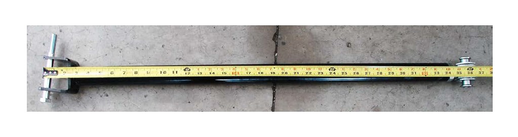
Component Starting Lengths For 2.5” Systems
2.5” Front Track Bar Assembled Length = 32 9/16”
2.5” Rear Track Bar Assembled Length = 39 3/4”
2.5” Front Lower Control Arm Assembled Length = 34 1/8”
2.5” Front Upper Control Arm Assembled Length = 36 1/4”
2.5” Rear Lower Control Arm (4 Door) = 34 1/8”
2.5” Rear Upper Control Arm (4 Door) = 26 3/4”
2.5” Rear Lower Control Arm (2 Door - Standard) = 33 5/8”
2.5” Rear Upper Control Arm (2 Door - Standard) = 27 1/4”
2.5” Rear Lower Control Arm (2 Door – 3” Stretch) = 36 ”
2.5” Rear Upper Control Arm (2 Door – 3” Stretch) = 30 3/8”
2.5” Rear Lower Control Arm (2 Door – 6” Stretch) = 39 38 ”
2.5” Rear Upper Control Arm (2 Door – 6” Stretch) = 32 3/4”
Component Starting Lengths For 3.5” System
3.5” Front Track Bar Assembled Length = 32 5/8”
3.5” Rear Track Bar Assembled Length = 39 3/4”
3.5” Front Lower Control Arm Assembled Length = 34 1/8”
3.5” Front Upper Control Arm Assembled Length = 36 1/4”
3.5” Rear Lower Control Arm (4 Door) = 34 1/2”
3.5” Rear Upper Control Arm (4 Door) = 26 3/4”
3.5” Rear Lower Control Arm (2 Door - Standard) = 33 5/8”
3.5” Rear Upper Control Arm (2 Door - Standard) = 27 1/4”
3.5” Rear Lower Control Arm (2 Door – 3” Stretch) = 36 ”
3.5” Rear Upper Control Arm (2 Door – 3” Stretch) = 30 3/8”
3.5” Rear Lower Control Arm (2 Door – 6” Stretch) = 39 38 ”
3.5” Rear Upper Control Arm (2 Door – 6” Stretch) = 32 3/4”
Component Starting Lengths For 4.5”/5.5” System
4.5”/5.5” Front Track Bar Assembled Length = 32 9/16”
4.5”/5.5” Rear Track Bar Assembled Length = 40.00”
4.5”/5.5” Front Lower Control Arm Assembled Length = 34.250”
4.5”/5.5” Front Upper Control Arm Assembled Length = 36.313”
5.5” Rear Lower Control Arm (4 Door) = 34.625”
5.5” Rear Upper Control Arm (4 Door) = 26.875”
4.5” Rear Lower Control Arm (2 Door - Standard) = 33.750”
4.5” Rear Upper Control Arm (2 Door - Standard) = 27.375”
4.5” Rear Lower Control Arm (2 Door – 3” Stretch) = 36 ”
4.5” Rear Upper Control Arm (2 Door – 3” Stretch) = 30 3/8”
4.5” Rear Lower Control Arm (2 Door – 6” Stretch) = 39 38 ”
4.5” Rear Upper Control Arm (2 Door – 6” Stretch) = 32 3/4”
Note: All Control Arms, Torque Arms, Track Bars and Triangulated 4 -Link Assemblies come preassembled, but they require final adjustment as specified in the directions above. These measurements are taken from the center of one bolt hole to center of the other bolt hole.
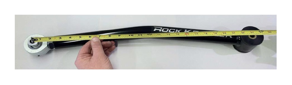
Please Note: The front upper arms can be tricky to set properly. Measure from the center of the mounting bolt to the center of the joint as shown.
TORQUE VALUES FOR HARDWARE AND JAM NUTS
• All 14mm and 9/16” bolts are torqued to 90-100 ft-lbs.
• All 12mm and ½” bolts are torqued to 75-80 ft-lbs.
• All 10mm and 3/8 bolts are torqued to 30-35 ft-lbs.
• All 7/8” Jam Nuts are to be torqued 200-220 ft-lbs. Up to 5/8” of threads showing past the jam nut is safe for final adjustment. These specifications are critical for the overall longevity of the threaded section.
• All 1” Jam Nuts are to be torqued to 250-300 ft-lbs. GET YOUR BIG BOY PANTS ON! Up to 3/4” of threads showing past the jam nut is safe for final adjustment. These specifications are critical for the overall longevity of the threaded section.
• All 1 1/4” Jam Nuts are to be torqued to 275-325 ft-lbs. GET YOUR BIG BOY PANTS ON! Up to 7/8” of threads showing past the jam nut is safe for final adjustment. These specifications are critical for the overall longevity of the threaded section.
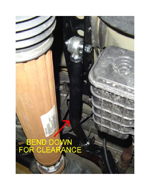
Please note: Before you start this procedure it is recommended that you have your front exhaust modifications completed prior to installation of the system so when your installation is completed you can drive your JK away safely. The recommended exhaust modification is shown below. Please note the exact procedure will vary depending on years and engine models. The goal of the exhaust modification is to clear the new long arm mount and the new long front upper control arm. It may be helpful to bring the mount and upper control arm to the exhaust shop. Ensure the exhaust is not routed where is can interfere with hardware going into the long arm mounts.
SUGGESTED EXHAUST MODIFICATIONS'07 – Early '10 JK's (3.8L V6)
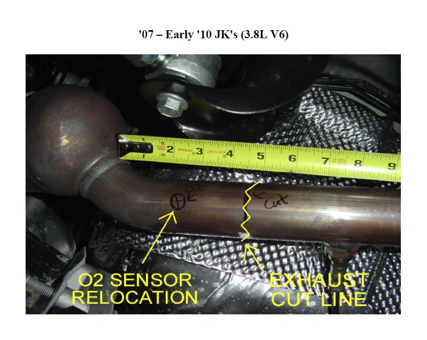
Remove the O2 Sensor and then cut the exhaust 4.5” back from the catalytic converter. Relocate the O2 Sensor 2.5” from the end of the first cat. Please note: the O2 Sensor will actually function better the hotter it is so moving it closer to the manifold will certainly not hurt its operation.
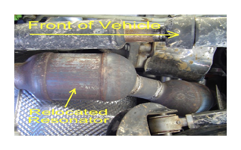
Relocated resonator after the Cat on the driver’s side after relocating the O2 sensor forward (it must be relocated between the cat and the resonator) flip the resonator over 180 degrees and weld it back in place as shown above.
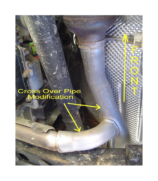
Modify the cross over pipe and tie the driver’s side resonator into the exhaust connection and then bring the entire exhaust system back together. Make sure your modifications allow for clearance for the new mounts and mounting hardware for the arms.
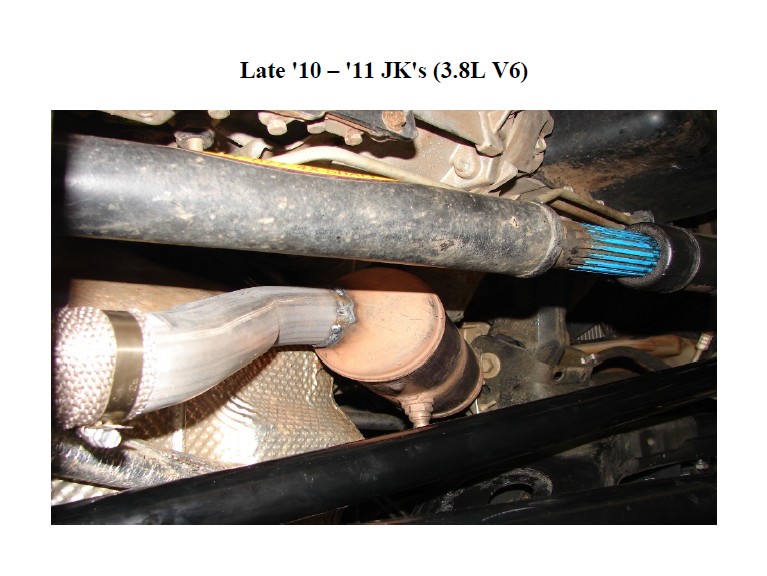
• Cut out the catalytic converters and relocate them as close to the exhaust manifolds as possible.
• Reroute the exhaust around the long arm mounts and tie both left and right pipes back into each other.
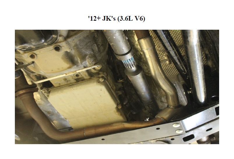
You will want to cut out the exhaust loop on the drivers side of the y-pipe. Then reroute the pipe around our control arm mount and tie the crossover pipe back into it. You will want to take into account the movement of the driveshaft during articulation as you are rerouting the pipes. Make sure that you do not have any contact at any point of your suspension movement. For 4 door applications a great starting point would be to use the Magnaflow Exhaust Loop Delete Kit – Ref. Part # 19211.
FRONT OF VEHICLE
1) Make sure vehicle is on a level, hard working surface if you are using a floor jack and jack stands.
2) Block the rear wheels so the vehicle cannot move and make sure the emergency brake is applied.
3) Raise the front of vehicle and support with safety jack stands. Locate jack stands on the frame in front of the axle.
4) If you are using a vehicle lift, place the lift arms according to those specific vehicles lifting procedures. Ensure that the lift arms will not interfere with the components that are being replaced.
5) Remove the front rims and tires with axle supported by a floor jack.
6) Remove the front shocks. Save the OEM hardware to install the new shocks.
7) Remove the front sway bar links.
8) Remove the bolt holding the factory brake line to the frame to add slack in the line. Be sure to add slack to the breather tube as well.
9) Lower the front axle assembly onto jack stands.
10) Remove the front track bar from the vehicle and save the OEM hardware for reuse.
11) Remove the front springs.
12) Remove the front lower control arms. Discard the arms, but save the hardware for reuse.
13) Remove the front upper control arms. Discard the arms and hardware.
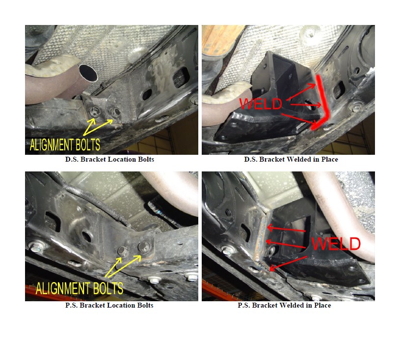
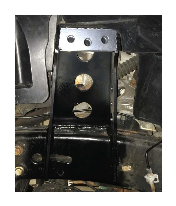
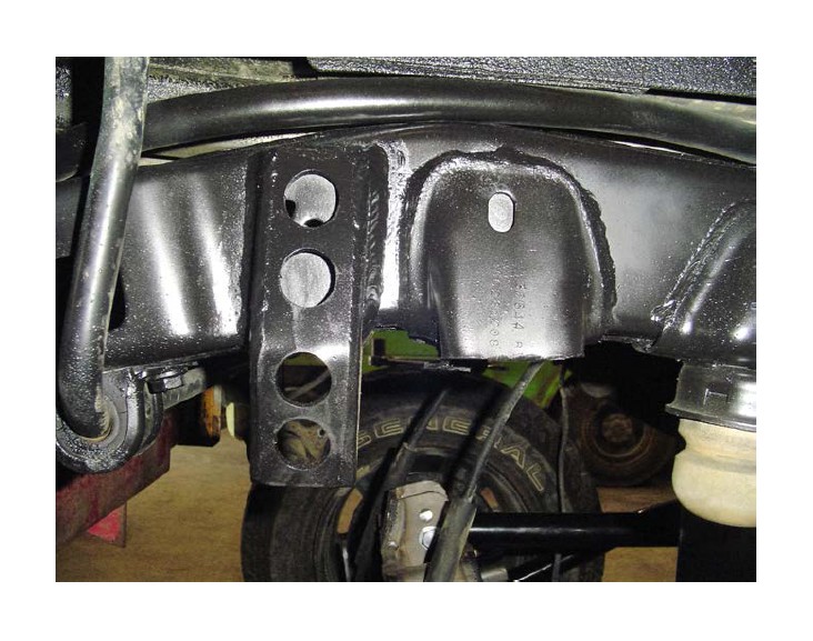
14) Install the front long arm mounts as shown below.
Please Note: The mounts bolt into position using the OEM cross member bolts and then weld in place. Use a full ¼” fillet weld. Be sure to prep the surfaces properly. Apply a finish of your choice.
15) Install the new cross member using the (4) supplied ½” x 1.25” carriage bolts, ½” lock washers, and ½” free running nuts.
16) Remove the OEM front upper and lower control arm mounts from the frame. Clean up the frame and apply a durable finish of your choice.
17) X FACTOR LONG ARM SYSTEMS ONLY: Remove the OEM passenger side front upper control arm mount off the axle. Clean up the axle and apply a durable finish of your choice.
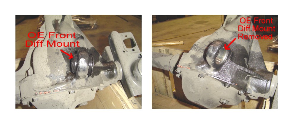
18) TRIPLE THREAT AND OFF-ROAD PRO SYSTEMS ONLY: Mark or note the position and orientation of the front upper control arm mount on the passenger side of the axle, then remove the OEM mount off the axle.
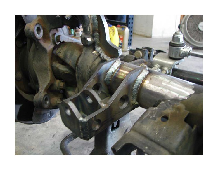
19) TRIPLE THREAT ONLY: Weld the new heavy duty axle mount on the passenger side axle tube in the same location and orientation as the OEM passenger side front upper mount was as shown below. Use a ¼” fillet weld all the way around its contact points with the axle tube as shown below. Then weld on the two gussets to give it lateral support. Apply a durable finish of your choice.
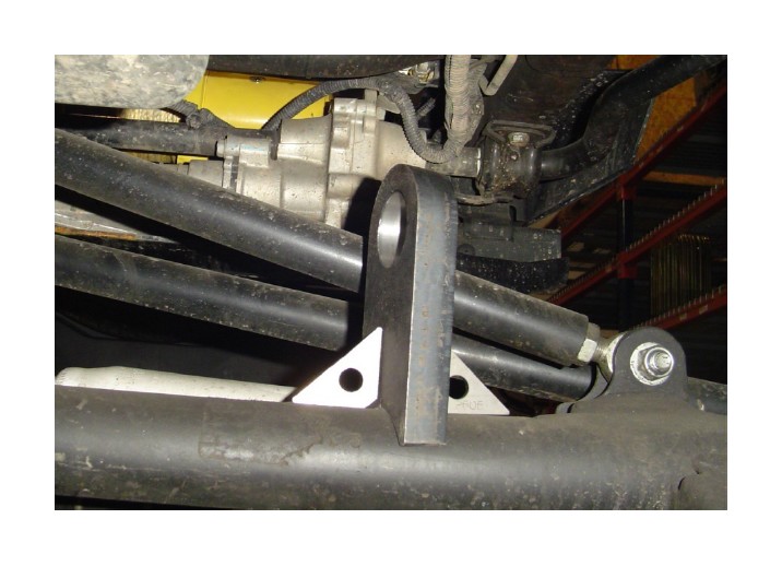
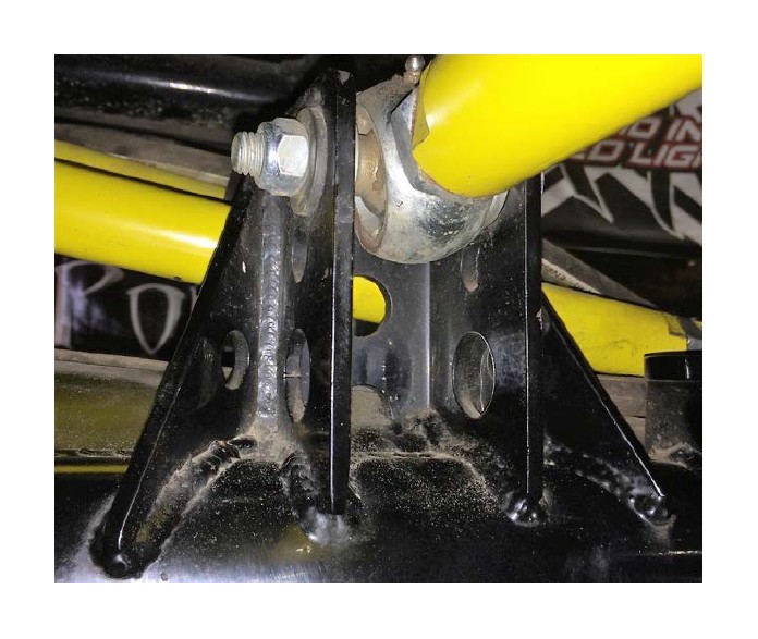
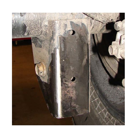
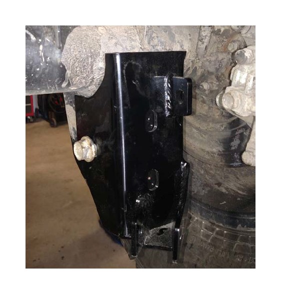
20) OFF-ROAD PRO SYSTEMS ONLY: Place the supplied off-road pro front upper mount in the same position and orientation as the OEM front upper mount was on the passenger side tube of the axle and weld in place as shown below. Helpful hint: When the caster is set on the axle, the front surface of the off-road pro front upper mount will be vertical.
21) FOR 4.5”/5.5” SYSTEMS ONLY OR IF YOU PURCHASED THE HIGH STEER UPGRADE: Install the supplied front track bar bracket using the factory hardware in the hole marked below to secure the new bracket. Place the supplied crush sleeve between new relocation bracket and the factory bracket.
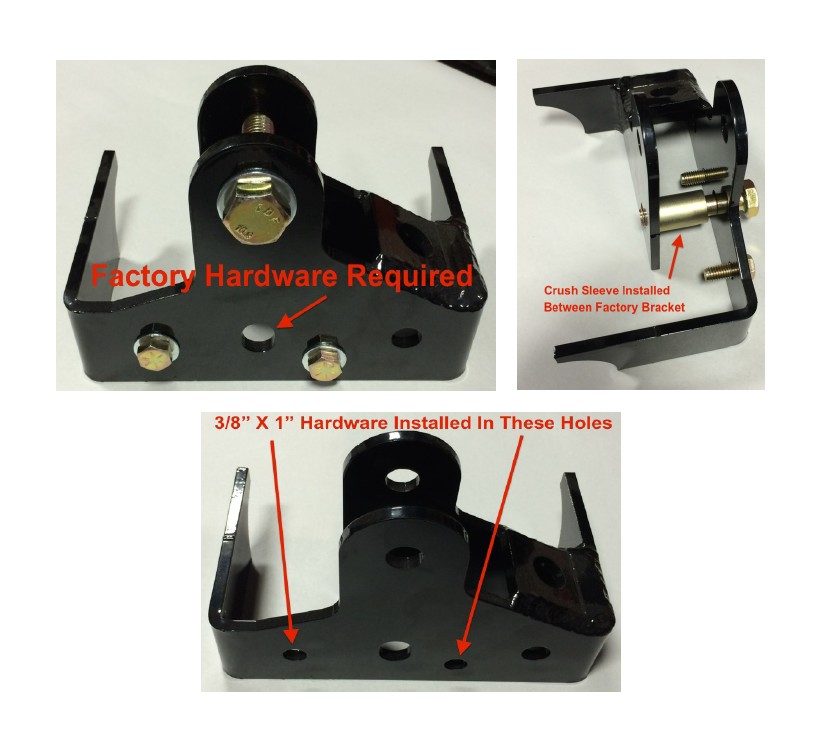
21a) Install the supplied 3/8” x 1” hardware with washers and nyloc nuts through the holes in the front of the new relocation bracket that line up with the OEM holes in the factory track bar bracket.
21b) Weld the new bracket to the axle tube using a 1/4” fillet weld around the radii of the bracket that contact the axle tube. Apply a durable finish of your choice.
22) Install the new upper coil over shock mounts.
22a) Remove the OEM coil spring and shock buckets from the frame completely as shown below.
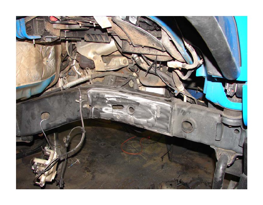
22b) Place the new coil over mounts on top of the frame rail. They are symmetrical so don’t worry about them being driver side or passenger side specific. The back edge of the bracket lines up with the front leading edge of the square hole next to the brake line mounting tab as shown. Fully weld the mount in place, then apply a durable finish of your choice.
22c) Remove the OEM shock mounting brackets off the front axle completely.
22d) Install the new lower coil over mounts on the axle. (These dimensions are based off OEM axles). The mounts should be ½” off the inside of the C and fully welded in place. Helpful Hint: With the caster set to 4 - 5 degrees, the top legs of the lower coil over mounts that go across the top of the axle should be at 0 degrees or horizontal.
23) X FACTOR AND TRIPLE THREAT ONLY: Remove the driver’s side OEM front upper control arm bushing on the axle as shown below.
Please note: This can be done by striking it on the steel sleeve. If you run into trouble drill out the rubber bushing material and then remove the entire assembly.
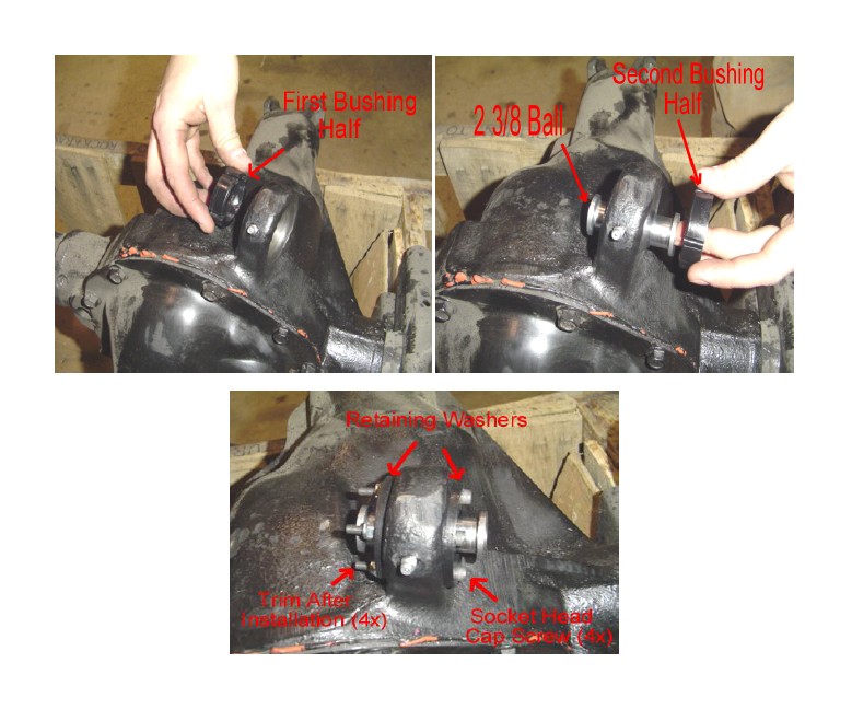
24) X FACTOR AND TRIPLE THREAT ONLY: Install the supplied build-a-ball joint into the casting of the axle as shown below.
Please Note: Install one bushing then the spherical ball and then the second bushing making sure the slots for the fasteners are on top and bottom for correct orientation. Place one of the supplied washers on each side and secure using the supplied #10-32 x 2.00” bolts and #10-32 nyloc nuts and torque evenly. The washers should come in contact with the housing. Cut off any extra bolt length that extends past the nut.
25) TRIPLE THREAT ONLY: Repeat procedure on passenger side in the newly supplied mount on the axle.
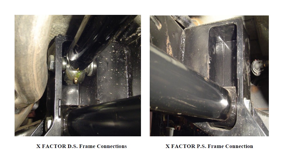
26) Install the new front upper control arm(s) set to the specified length for application. Secure using the supplied 14mm x 100mm bolts, washers, and nyloc nuts at both ends. X FACTOR ONLY Check the clearance between the clevis mount on the arm and your electric locker connection if you have a Rubicon Model.
Please Note: X FACTOR SYSTEMS have only one front upper control arm on the driver side. OFF-ROAD PRO SYSTEMS have only one front upper control arm on the passenger side. TRIPLE THREAT SYSTEMS have both driver side and passenger side front upper control arms. Do not allow more than 3/4” of thread to show past any jam nut for proper thread engagement.
27) Install the front lower control arms set to the specified length for your application.
*Please Note: X FACTOR AND TRIPLE THREAT: the bend in the arm is for improved ground clearance and go up. The Krawler Joint (Zinc Plated Spherical Joint) goes to the axle and the Pro Flex Joint (Bushing Joint) goes to the frame. OFF-ROAD PRO are straight arms with double Krawler Joints. They have no specific orientation. Do not allow more than 1” of thread to show past any jam nut for proper thread engagement.
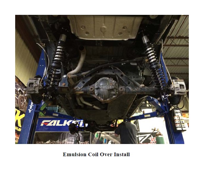
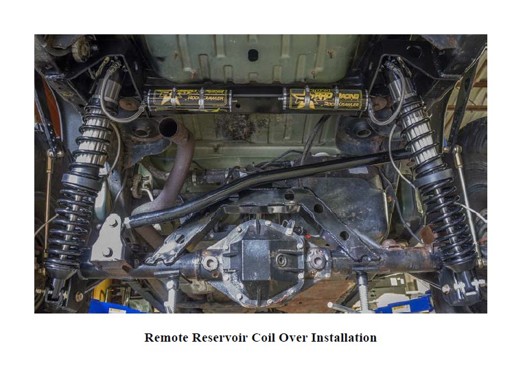
28) Install the supplied coil over shock assemblies with the supplied ½” x 2.75” bolt, washers and nylok nuts on both top and bottom.
Please Note: You want to have a minimum of 4.5” of compression. Use the spanners on the coil overs to adjust the height of the vehicle until your desired stance and lift is achieved. For remote reservoir applications, the reservoir attaches directly to the back side of the upper shock mount using the supplied hose clamps.
29) As you are compressing the suspension, install the front track bar reusing the OEM hardware in the OEM location(s) or the supplied 14mm x 80mm bolt, washers and nylok nut in the raised axle mount location. Be sure to set it to the starting dimensions for your system as specified above and balance the amount of thread showing past the jam nut on each end. The rebuildable Anti-Wobble joint goes to the frame connection and the heim joint with high misalignment spacers go to the axle connection as shown below. Helpful hint: Be sure to have the steering column unlocked so the axle will swing side to side freely.
*Please Note: If for some reason you happen to remove the joints from the bar, the Anti-Wobble Joint goes in the short leg and the Heim Joint goes in the long leg. When installed, the bend of the bar goes up! Orientation of the bar is set by locking the jam nut at the frame connection. Do not allow more than 5/8” of thread to show past any jam nut for proper thread engagement. If you find it difficult to get at the jam nuts properly in the vehicle, remove the track bar and tighten the jam nuts in a vice making sure to hold the orientation of the joint while doing so.
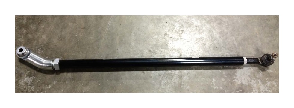
30) FOR 4.5”/5.5” SYSTEMS ONLY OR IF YOU PURCHASED THE HIGH STEER UPGRADE: Install the Off-Road Pro HD Drag Link
30a) Disconnect and remove the drag link from the vehicle using a ball joint separator or dead blow technique. Note the OEM drag link length. Save the Tie Rod End at the pitman arm for reuse if it is in good condition
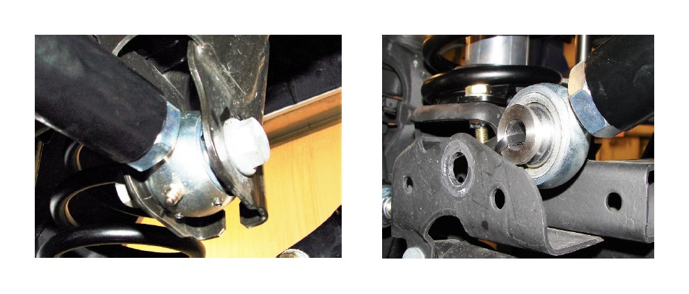
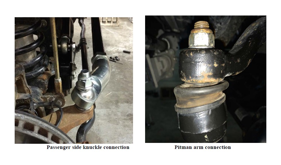
30b) Drill out the passenger side knuckle mounting position for the drag link to 11/16” as shown below.
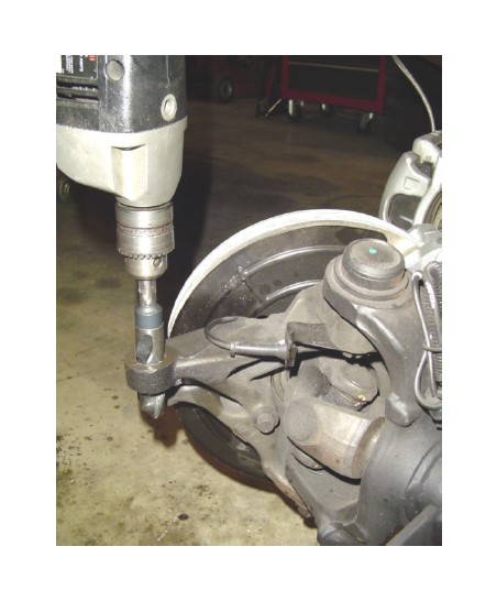
Please Note: It may take a slight ream to get the hardware to pass through. The tighter the hardware to the hole the better.
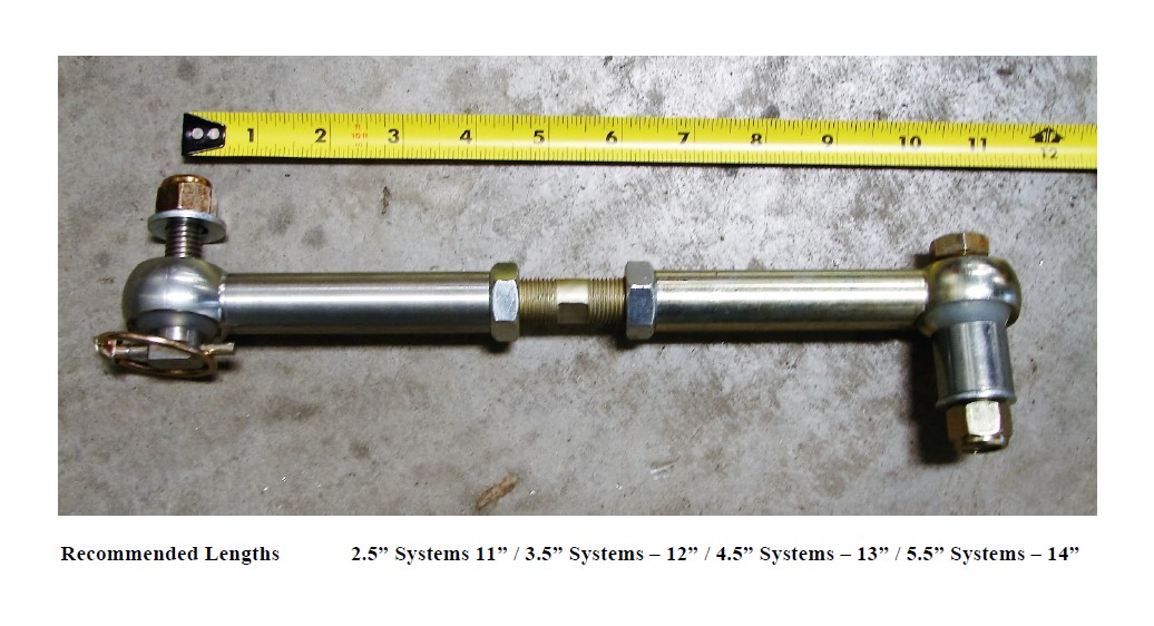
30c) Assemble your new HD Drag Link like shown below with the supplied jam nut installed on the factory Tie Rod End and the Tie Rod End threaded into the HD Drag Link.
30d) Set your new HD Drag Link to the length of the factory assembly you noted.
30e) Install the new HD Drag Link using the supplied hardware to the top of your passenger side knuckle and the factory Tie Rod End hardware at the pitman arm connection.
Please Note: You can go back to the OEM geometry if the need ever arises. Simply purchase our flip spacer and follow the directions included.
30f) Center your steering wheel by adjusting the new HD Drag Link.
30g) Ensure that both joints are in phase with each other (misaligned in the same direction) as shown in the images below before you tighten the jam nuts on the joints.
31) Install the newly supplied Pro Disconnects/Extended Links. Set the length of the assemblies as noted below.
*Please Note: These are recommended starting lengths. Fully cycle the suspension for clearance/interference checks once your installation is complete to ensure proper operation.
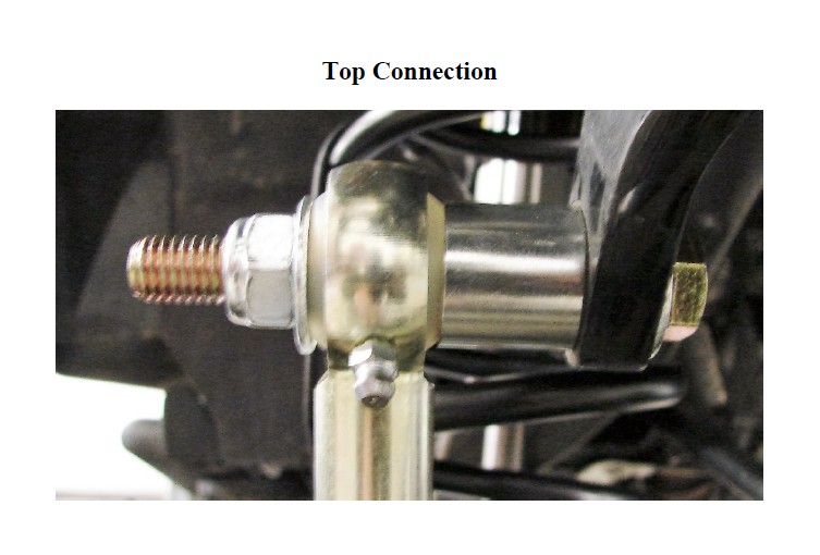
Top Connection: Working from the inside out, you have the head of the supplied 12mm x 80mm bolt, 12 mm washer, sway bar, shoulder of the billet spacer/sleeve, top joint of the sway bar link, 12mm washer then the supplied nylok nut as shown above.
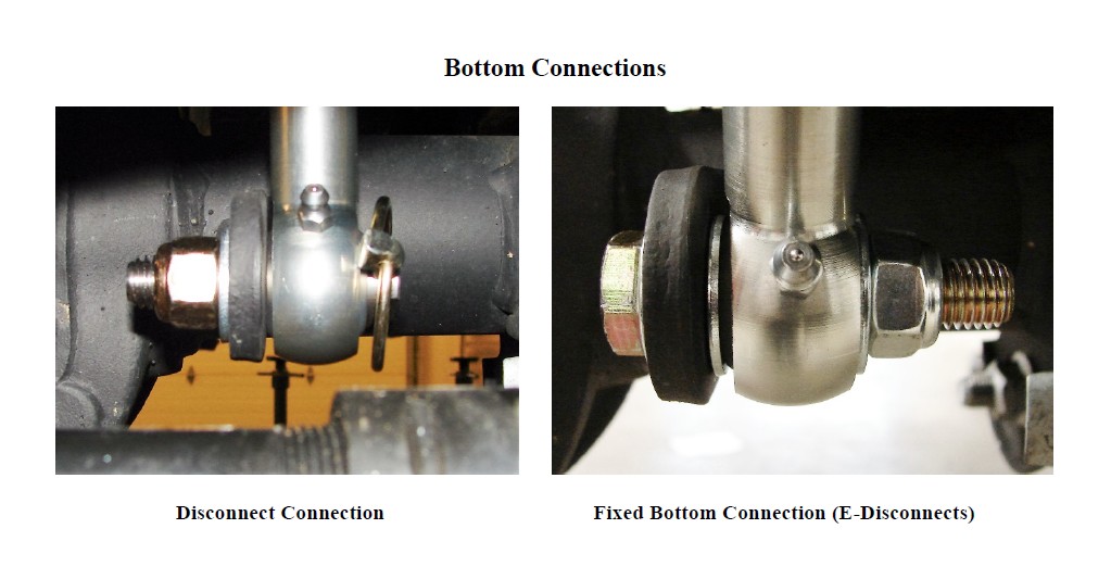
Disconnect Connection: Secure the supplied stainless steel disconnect bar pin to the OEM mounting tab with the supplied ½” washer under the supplied ½” nylok nut. Orient the lynch pin hole in an orientation most convenient for you to get at and make it as easy as possible to remove and disconnect the sway bar.
Fixed Bottom Connection: In the hardware package you will find a supplied 12mm x 50 mm bolt, straight sleeve (3/4” O.D. x ½” I.D.), washers and nylok nut. Remove the standard disconnect pin and insert the straight sleeve into the ball of the link. Secure as shown above with the head of the bolt, washer under the head of the bolt, washer on each side of the ball and the nylok nut.
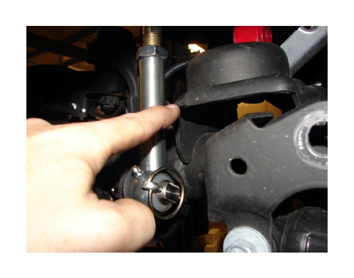
*Please Note: There are instances when clearance is tight between the link and the corner of the stock spring mounting pad. It may be required for you to clearance the corner of the spring pad as shown below. Use your discression to ensure this is done if required.
*Please Note: For those of you using the conventional disconnect feature we have supplied sway bar retainer straps for your convenience.
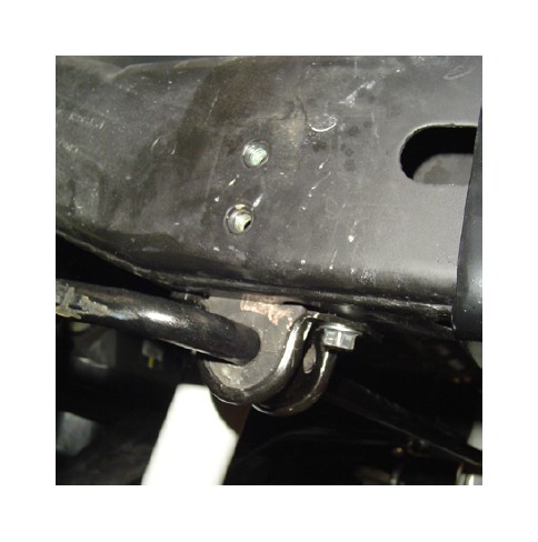
To install your sway bar link straps:
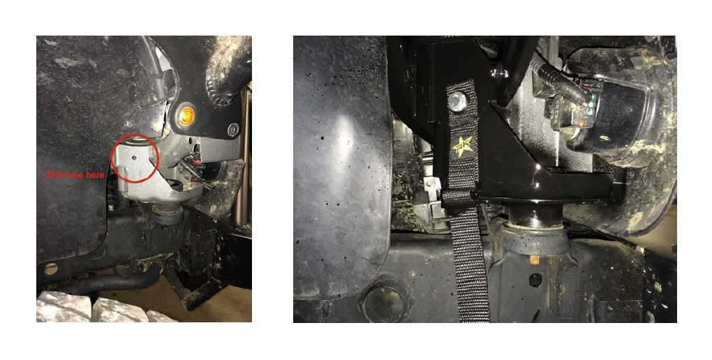
Drill a 5/16” hole in the sheet metal as shown in the picture below to the left and secure the fixed end of the sway bar link strap with the supplied 5/16” x 1” bolt, washers and nylok nut as shown below to the right.
When disconnecting, wrap the sway bar link strap around the sway bar and link. Then secure them up and out of the way. When not using the sway bar straps it is recommended the bottom end of the straps be removed and stored in a safe storage place.
32) Remove the OEM rubber brake lines. Install the supplied extended stainless steel brake lines (Part Number RK02038). Be sure to add slack to your ABS lines and route them with your new stainless steel lines. Use the supplied zip ties to secure them to each other. Do not worry about bleeding the brake system at this time unless your kit does not come with rear brake lines.
*Please Note: The factory front brake lines on a 07'-10' are routed different then the front brake lines on a 11' . We use the same brake line for all of our JK products thus we require you to route the line on the 11' just as if you were routing a line on the prior year JK's. The 15 degree angle built in the fitting is designed so the line is pushed away from the tire and wheel assembly. See the photos below to reference your new front brake line and ABS line routing.
33) Put the tires and wheels back on the front end and carefully lower the vehicle to the ground. Get ready to work on the back end.
REAR OF VEHICLE
1) Make sure vehicle is on a level, hard working surface if you are using a floor jack and jack stands.
2) Block the front wheels so the vehicle cannot move.
3) Raise the rear of vehicle and support with safety jack stands. Locate jack stands on the frame behind the rear axle.
4) If you are using a vehicle lift, place the lift arms according to those specific vehicles lifting procedures. Ensure that the lift arms will not interfere with the components that are being replaced.
5) Remove the rear rims and tires with axle supported by a floor jack.
6) Remove the rear shocks. Save the OEM hardware for reuse.
7) Remove the rear sway bar links.
8) Remove the wire hanger for the rear emergency brake cable and route them to have as much slack as possible.
9) Remove the bolt holding the factory brake line to the frame to add slack in the line. Be sure to add slack to the breather tube as well.
10) Lower the rear axle assembly onto jack stands.
11) Remove the rear coil springs.
12) Remove the rear track bar, save the OEM hardware for reuse.
13) Remove the rear lower control arms, save the OEM hardware for reuse.
14) Remove the factory rear upper control arms. Discard the arms and hardware for they will not be used.
15) Mark the position and orientation of the OEM rear track bar bracket on the axle. This is extremely important. You will be removing the problematic rear track bar bracket and replacing it with the newly supplied heavy duty one as shown below. Fully weld the track bar bracket in place in the OEM position and orientation using a ¼” fillet radius. Apply a durable finish of your choice after welding.
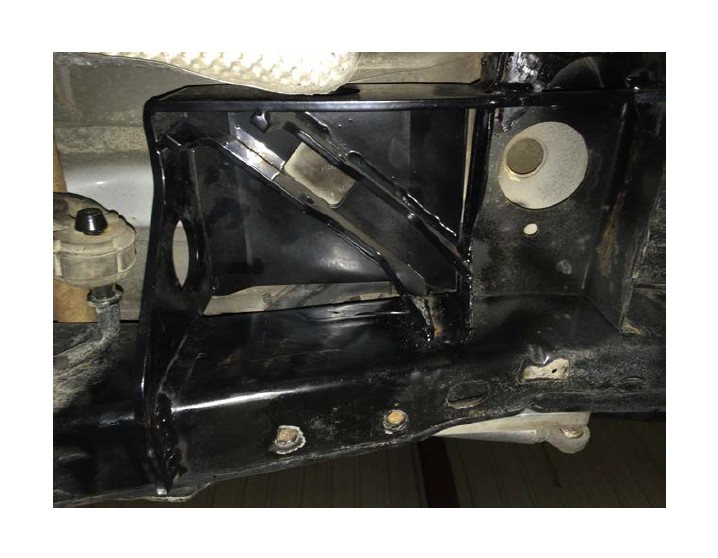
16) Install the rear upper control arm mount onto the frame. The bracket spans the two rear frame cross members and aligns off the holes in each cross member as shown below. Clamp the bracket with the holes aligned to the cross members and weld it in place using a ¼” fillet weld. Apply a durable finish of your choice after welding.
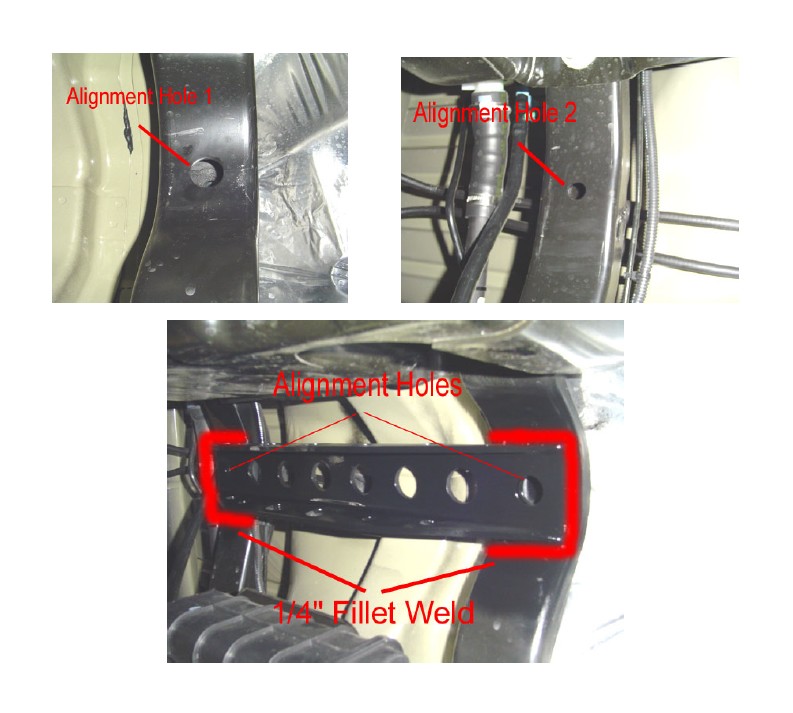
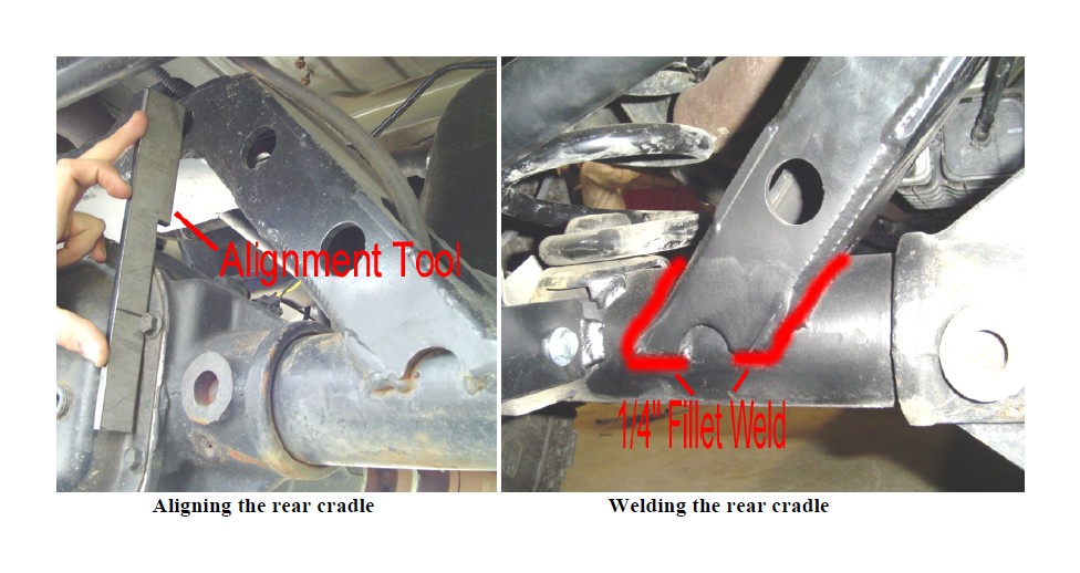
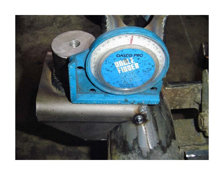
17) Install the cradle onto the rear axle. Center the cradle left to right on the axle and make sure the third link mount on the top is open to the front. Then hold the offset tool as shown below against the factory differential cover and rotate the cradle back until it contacts the offset tool. Weld it in place on front and back using a ¼” fillet weld as shown below. Apply a durable finish of your choice after welding.
*Please Note: Our rear cradle is designed around OEM axles. We do have a direct fit application for Pro Rock 60 rear axles. Currie 60’s will require some customization.
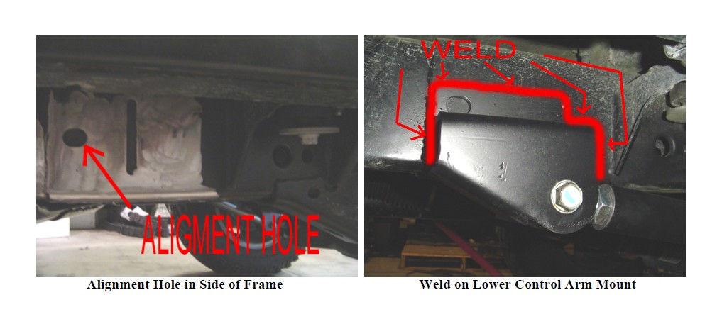
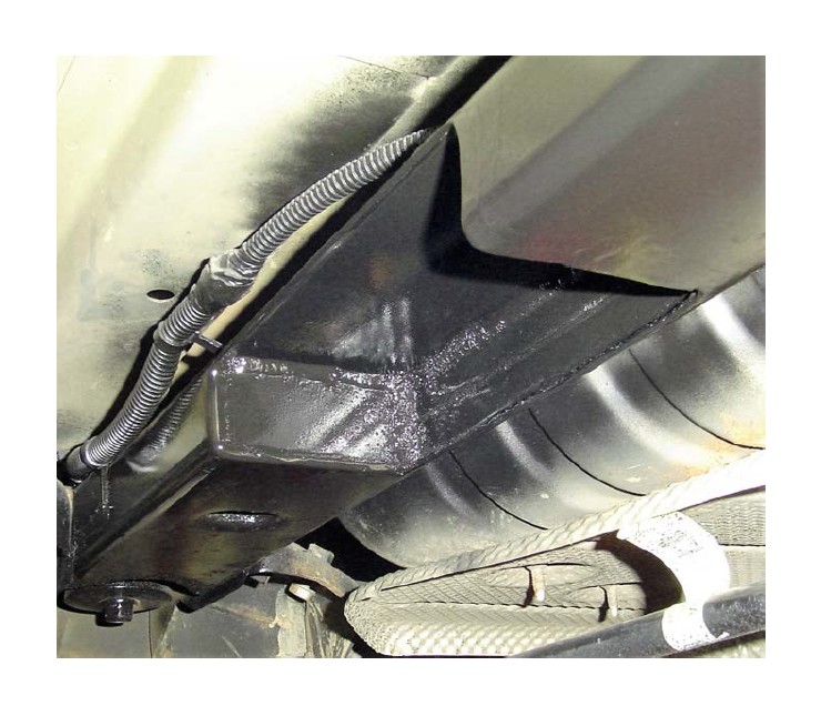
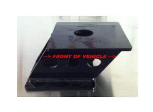
18) Install the supplied rear long arm mounts on the frame. The mounts locate off the slotted hole in the side of the frame as shown below. Weld them in place using a ¼” fillet weld.
Please Note: Keep the top edge of the mount horizontal when welding in place. There is a specific driver side and passenger side, the open end of the mount faces reward as shown below. Shown below is the driver’s side only.
19) Remove the OEM rear lower/upper control arm mounts on the frame and the upper control arm mounts on axle. Once the mounts are cleaned up, apply a durable finish of your choice.
20) FOR COIL SPRING STRETCH SYSTEMS ONLY PERFORM THE FOLLOWING:
20a) Mark the position and orientation of the OEM spring pads on the axle as shown below;
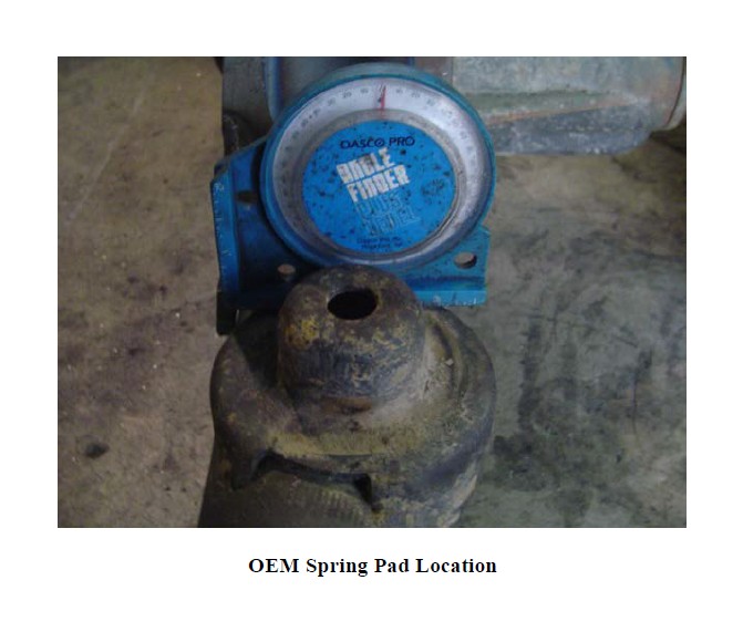
20b) Install the newly supplied spring pads and tack weld them in place following the rules of thumb below;
- For 2.5” lift height: orient the supplied spring pad 3 to 5 degrees down from the factory pad orientation
- For 3.5” lift height: orient the supplied spring pad 5 to 7 degrees down from the factory pad orientation
- For 4.5” lift height: orient the supplied spring pad 7 to 9 degrees down from the factory pad orientation
Please Note: These orientation corrections should correct for pinion rotation. The spring pads should be horizontal at ride height on a level surface. Once proper pinion angle and spring pad positioning is verified, fully weld in using a ¼” fillet weld. Then apply a durable finish of your choice.
20c) Install the new frame mounted track bar bracket as shown below. The 3” stretch mount should be mounted 3” back from the OEM position. The 6” stretch mount should be mount 6” back… Be sure the trim the new mount so it is square and fully weld in place. Once completed you can completely remove the OEM mount from the frame.
20d) For some applications it will be required for you to trim the OEM cross member as shown below for cradle and rear upper arm clearance. We recommend performing the trim operation, then box it back in and apply a durable finish of your choice.
20e) For 3” stretch applications, typically the OEM shock mounting locations can be used. For 6” stretch applications, custom shock mounting positions will need to be determined, fabbed and implemented. That is why we do not sell our 6” stretch systems with rear shocks. If you want RRD Spec’d Prodigy Shocks for the rear of your JK with a 6” stretch, please give us a shout with your specifications.
21) FOR REAR COIL OVER SYSTEMS ONLY PERFORM THE FOLLOWING;
21a) Remove the OEM factory rear upper shock mounts off the frame.
21b) Install the supplied rear upper coil over brackets in the same position as the OEM shock mounts were as shown below. Weld them to the frame and the cross member at all points of contact using a ¼” fillet weld. Once in place apply a durable finish of your choice.
21c) Remove the rear sway bar link mounting tabs and shock mounting tabs from the rear lower control arm axle mounts as shown below. Apply a durable finish of your choice.
21d) Bolt in place the newly supplied mount using the OEM lower control arm mounting hardware as your guide. Mark the two extra holes on the back of the bracket and drill out the OEM hole to ½”. Bolt the two mounts together with the supplied ½” x 1.25” bolts, washers and nylok nuts and the OEM lower control arm mounting hardware.
22) Install the supplied rear upper control arm set to the specified length for your kit according to our measurements. Secure using the supplied 14mm x 90mm bolts, washers, and nylok nuts.
Please Note: The bend in the rear upper control arm goes down to allow for greater up travel of the suspension. It is recommended that this jam nut on the frame side joint be loctited and tightened outside the vehicle due to the tight space it is in. The rear cradle has adjustable anti-squat holes built into it. It is recommended that you start out on the middle hole in the cradle, and then adjust to your liking and driving style. Moving the arm up one position will cause more anti-squat and going down one position will cause less anti-squat. We supply an arm based on stock low pinion rear axles. If you need an arm for a high pinion rear axle, please call Rock Krawler directly. Our standard rear upper arms are designed around factory style or low pinion rear axles. If you need an arm for a custom application, please give us a call.
22) Install the rear lower control arms set to the specified length for your application.
*Please Note: X FACTOR AND TRIPLE THREAT: the bend in the arm is for improved ground clearance and go up. The Krawler Joint (Zinc Plated Spherical Joint) goes to the axle and the Pro Flex Joint (Bushing Joint) goes to the frame. OFF-ROAD PRO are straight arms with double Krawler Joints. They have no specific orientation. Do not allow more than 1” of thread to show past any jam nut for proper thread engagement.
23) For STANDARD WHEEL BASE COIL SPRING REAR SYSTEMS (NON-STRETCH); Install the spring correction degree shims under the rear coils on the axle. The thick part of the shim goes towards the rear of the vehicle as shown below.
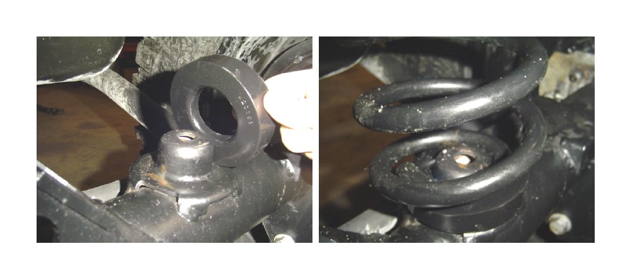
24) FOR ALL REAR COIL SPRUNG SYSTEMS: Install the Rock Krawler rear coil springs. Make sure to put the end of the coil winding all the way to the rear of the lower coil pad.
Helpful Hint: A simple and cost effective way to retain the rear coils to the axle is to use a hose clamp up through the center hole of the spring pad and clamp it around the bottom winding of the coil spring
25) FOR ALL REAR COIL OVER SYSTEMS: Install your rear coil over assemblies using the supplied ½” x 2.75” bolts, washers, and nylok nuts.
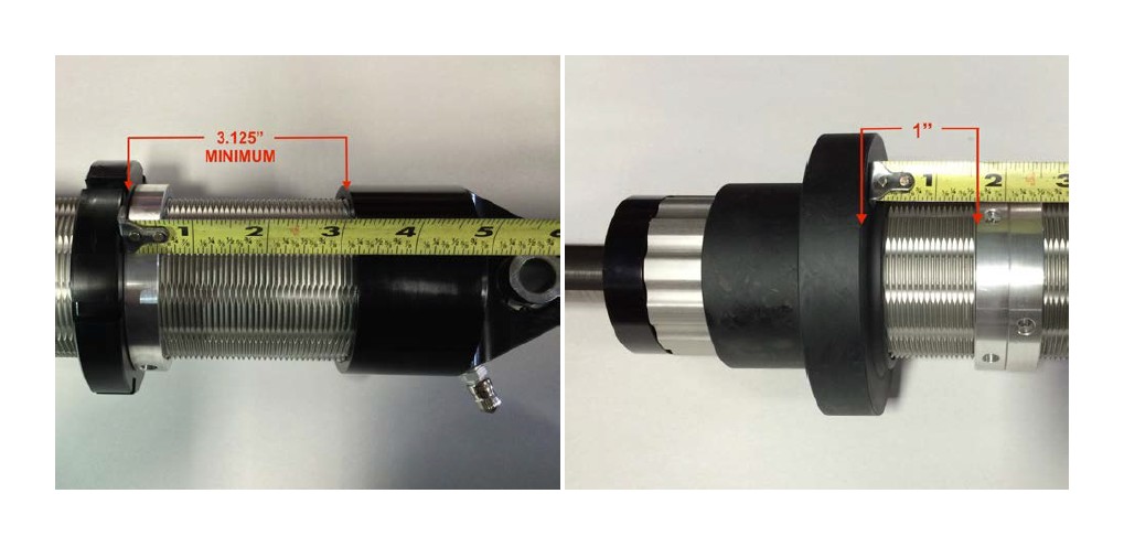
Helpful Hints: Setting Up and Adjusting Your Rear Coil Overs.
The lift height is set by adjusting the top coil spring seats. You will want to set the top spring seat no less then 3 1/8” from the bottom of the of the coil-overs top cap. This will ensure that your coil does not hit the frame during heavy articulation.
The transition rings or cross over rings (how ever you would like to refer to them) are a key point of adjustment for ride quality and performance. Once you establish your ride height, start with the transition rings 1” off the plastic spring slider. If you find yourself hard bottoming the coil overs in the rear, then spin down the transition rings closer to the plastic slider. If not, spin up the transition rings until you find yourself hard bottoming the rear coil overs, then come back down just a little bit to prevent or minimize hard bottoming. It is never good to hard bottom coil overs and this should be minimized and or eliminated. Potential failures can occur.
26) Install the supplied rear track bar set to the specified length for your kit according to our measurements. Secure the frame connection with the OEM hardware and the axle connection with the supplied 14mm x 80mm bolt, 14mm washers, and 14mm nylok nut.
*Please Note: When setting length, balance the amount of thread showing past the jam nuts. Just like the front track bar, the Anti-Wobble Joint goes to the frame and the heim joint end goes to axle. The bend in the track bar is for clearance of the differential and the orientation of the track bar is controlled by locking the jam nut of the Anti- Wobble Joint at the frame. Once the vehicle is on the ground, you will need to check that the axle is centered under the vehicle. If not centered, adjust the track bar so the axle is centered. If your coil spring and track bar make contact, you can break the jam nuts free on the track bar while it is bolted in place. Then roll the bend of the bar back away from the coil spring and Loctite and tighten your jam nuts again. If you still have issues after doing this, you may need to adjust your pinion angle and/or wheelbase by adjusting the control arms. Do not allow more than 3/4” of thread to show past any jam nut for proper thread engagement.
27) Relocate the rear sway bar mounting brackets back 1” for standard systems, 3” for 3” stretch and 6” for 6” stretch. Unbolt the rear sway bar mounting brackets from the frame, measure one inch back from each mounting hole, mark and drill 4 new holes with a 5/16” drill bit. Using the (4) supplied 3/8 thread forming screws, remount the rear sway bar.
*Please Note: Use WD-40 or lubricant on the supplied thread former screws to start them. This will make the process easier. Torque them down to 25 to 30 ft-lbs.
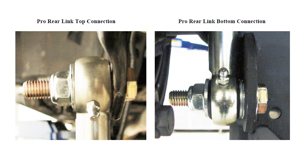
28) Install the Rear Pro Sway Bar Links. Set the assembled length as shown below.
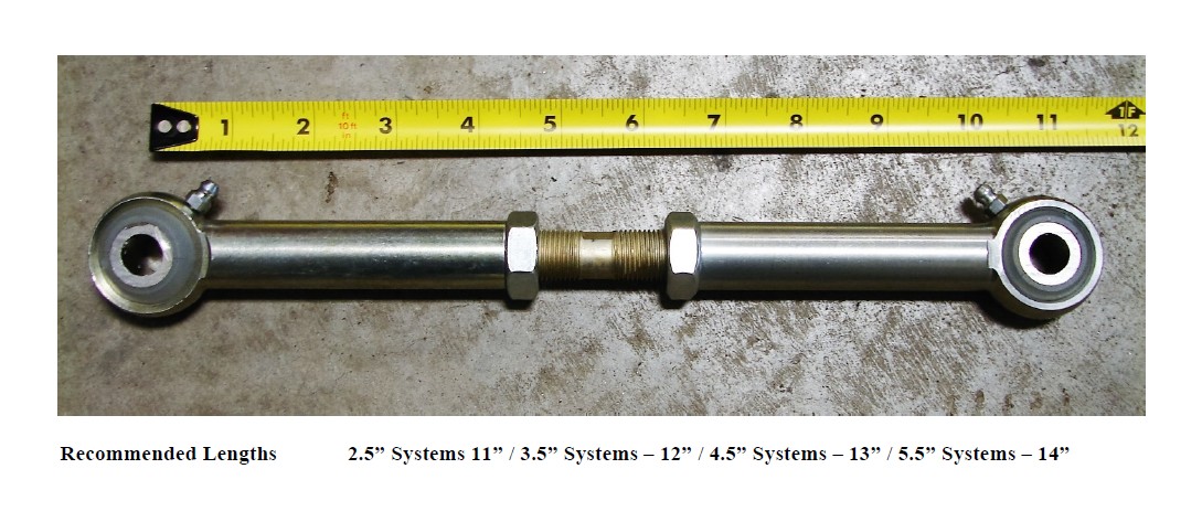
The top connection uses the supplied 12mm x 50 mm bolt, washers and nylok nut as shown below. Under the head of the bolt, there is a washer and on each side of the sway bar link ball joint there is a washer and finally they are secured with the nylok nut.
The bottom connection uses the supplied 12mm x 50 mm bolt, washers and nylok nut as shown below. Under the head of the bolt, there is a washer. Between the sway bar link ball joint and the OEM mounting bracket, there are two washers to provide extra clearance between the housing and the billet link end, then there is one more washer on the other side of the joint, then finally secured by the nylok nut.
29) Install the rear shocks using the OEM hardware.
Please Note: We recommend the rear shock bodies should be no more than 2” in diameter or there is a risk of the rear shock contacting the rear track bar relocation bracket.
30) Install bump stops if purchased additionally.
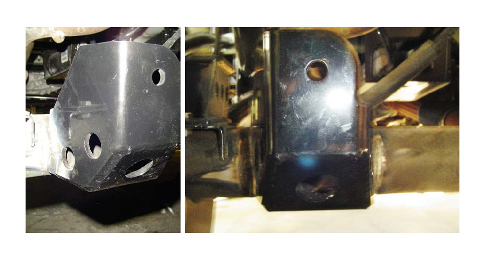
Please Note: Our rear fabricated bump stops mount to the factory bump stop pad on the rear axle using the supplied hardware. Use the existing holes in the factory pads. Make sure the bumps stop angles to the front of the vehicle as shown in the photo below.
31) Remove the factory front rubber brake lines and install the supplied extended stainless steel brake lines. Be sure to add slack to the ABS line, then secure the ABS and stainless steel brake lines together with zip ties and route them carefully. Now you can go ahead and bleed the brake system per the JK service manual.
32) Install the rear wheels and tires and lower the vehicle to the ground.
33) Tighten all mounting bolts at this time!
Recommended Alignment Specs are as follows;
2.5” Lift Height: 4.5 to 6.0 degrees of Caster with a .2 to .4 Cross Caster Split (.2 to .4 degrees more caster on the pass. side than the driver’s side.)
3.5” Lift Height: 4.2 to 5.5 degrees of Caster with a .2 to .4 Cross Caster Split (.2 to .4 degrees more caster on the pass. side than the driver’s side.)
4.5”/5.5” Lift Height: Minimum of 4.0 degrees of Caster with a .2 to .4 Cross Caster Split (.2 to .4 degrees more caster on the pass. side than the driver’s side.)
Tow: 0 to slightly towed in but within factory specifications
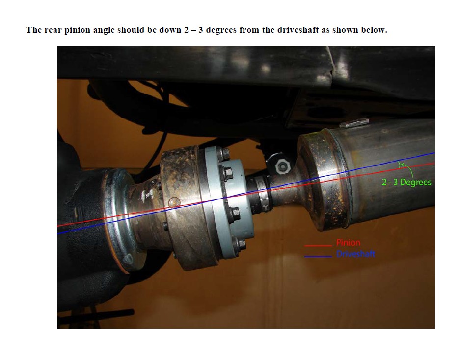
The rear pinion angle should be down 2 – 3 degrees from the driveshaft as shown below.
Before hitting the pavement or the trails be sure to make sure the control arms are oriented properly, all spherical joints (heim joints and Krawler Joints) are oriented correctly to allow for maximum movement without bind, and all jam nuts have Loctite on them and are tight. Make sure the axles are properly centered, pinion angles are correct, there is proper slack in ABS lines, and all lines are properly routed. Go back over all your hardware and make sure each connection is tightened to its proper torque spec. Check your vehicles articulation and ensure that no moving parts contact or interfere with any other components throughout the travel (brake lines, shocks, coils, sway bar links). Also check to see if at full flex your coil spring losses tension, if so you may want to look into a limit straps. You may need to look at bump stops depending on what shocks you choose to run.
Congratulations, you have just finished installing your Rock Krawler Suspension System! Your Jeep is now free to roam about the country.