FREE 1 to 3-Day Delivery on Orders $149+ Details

How to Install a Rhino-Rack Vortex RLCP 3 Bar Backbone Hard Top Roof Rack on your 2007-2017 Jeep Wrangler JK 4 Door
Installation Time
3 hours
Tools Required
- 10mm Spanner
- 13mm Spanner
- Drill
- 3.0mm Drill Bit
- 6.5mm Drill Bit
- 5mm Allen Key (supplied)
- Support Stands
- 6-18mm Step Drill
- Tape Measure
- Marker Pen
- 4mm Allen Key (supplied)
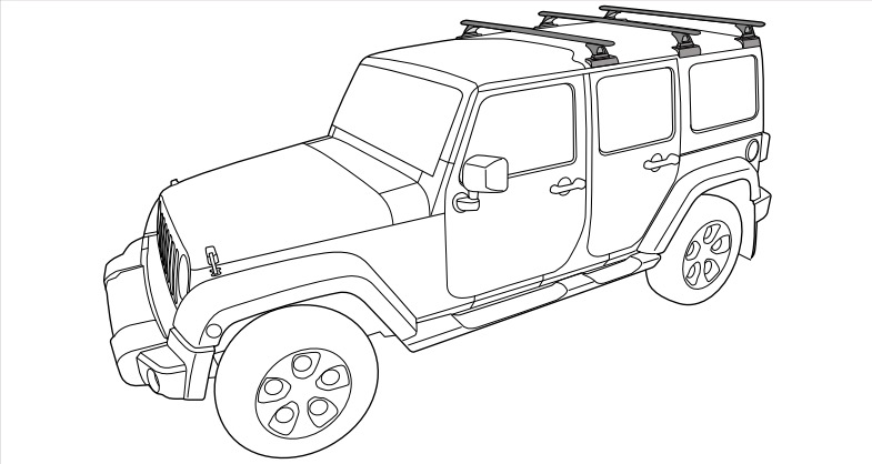
Jeep Wrangler JK 4dr Hard Top 2007 On
Important Information:
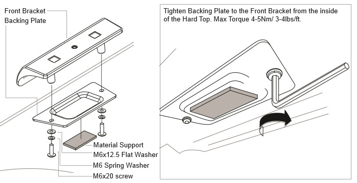
Max: 120kg (264lbs) - Three Crossbars. Max: 100 (220lbs) - Two Crossbars.
Read through instructions before installation. If you are unsure or have any questions, refer to the dealer or place of purchase.
Recommendations:
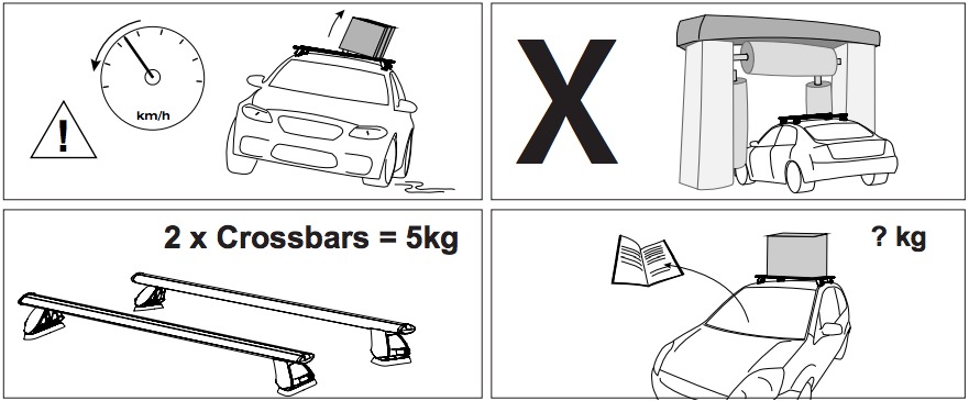
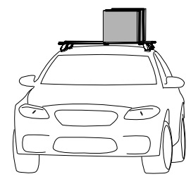
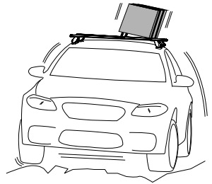
It is essential that all bolt connections be checked after driving a short distance when you first install your crossbars. Bolt connections should be checked again at regular intervals (probably once a week is enough, depending on road conditions, usage, loads and distances travelled). You should also check the crossbars each time they are refitted. Make sure to fasten your load securely. Please ensure that all loads are evently distributed and that the center of gravity is kept as low as possible. Use non stretch ropes.
Please remove crossbars when putting vehicle through an automatic car wash.
Load Ratings:
Maximum permissible load is 120kg (264lbs) for three crossbars including the weight of the crossbars, 7.5kg (16lbs) for three bars and 5kg (11lbs) for two bars. When crossbars are to be used in off-road conditions, please build a safety factor of 1.5 into this load limit for off-road use, three crossbars = 80kg (176lbs) and two crossbars = 66kg (145lbs). Although the crossbars are tested and approved to AS1235-2000, Off road conditions can be much more rigorous. However, increading the number of crossbars does not increase the vehicles maximum permissible roof loading.
Note for Dealers and Fitters: This is a two person installation. The removal of the hard top requires assistance. It is your responsibility to ensure instructions are given to the end user or client.
Rhino-Rack
3 Pike Street, Rydalmere,
NSW 2116, Australia.
(Ph) (02) 9638 4744
(Fax) (02) 9638 4822
Document No: R433
Prepared By: Kayle Everett
Authorised By: Chris Murty
Issue No: 04
Issue Date: 18/09/2014
When these roof racks are to be used on a vehicle that is driven off sealed roads the maximum load rating must be divided by 1.5. Remember to subtract the weight of the roof racks to determine your maximum permissible load capacity.
3 bars 120kg 3 bars 80kg
(264lbs) (176lbs)
2 bars 100kg = 2 bars 66kg
(220lbs) load rating (Urban road) (145lbs) load rating (Off road)
Load rating not taking into account crossbar weight - 5kg
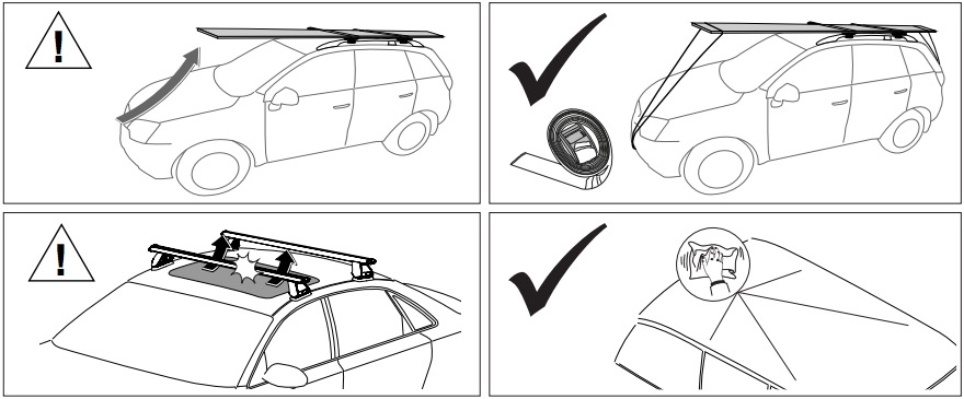
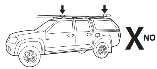
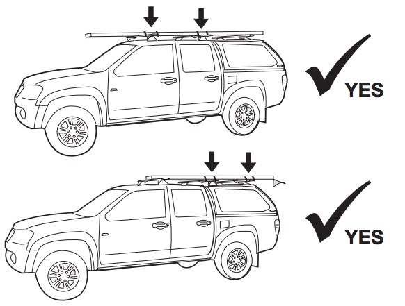
WARNING! Important Load Carrying Instructions
With utility vehicles, the cabin and the canopy move independently. Roofracks and vehicle can be damaged if the item transported is rigidly fixed at points on both the cabin and canopy. Instead, rigidly fix to either the cabin roofracks or the canopy roofracks.
Parts List
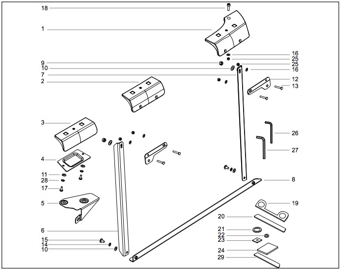
| Item | Component Name | Qty | Part No. |
|---|---|---|---|
| 1 | Rear Bracket | 1 (R) 1 (L) | CA1274 |
| 2 | Middle Bracket | 2 | CA1275 |
| 3 | Front Bracket | 2 | CA1276 |
| 4 | Backing Plate | 2 | CA1277 |
| 5 | Front Support Plate | 1 (R) 1 (L) | CA1278 |
| 6 | Internal Support Vertical | 2 | CA1279 |
| 7 | Internal Support Vertical | 2 | CA1280 |
| 8 | Internal Support Base | 1 (R) 1 (L) | CA1281 |
| 9 | M8 Nyloc Nut Black | 4 | N043 |
| 10 | M8 Flat Washer Black | 4 | CA1068 |
| 11 | M6x12.5mm Flat Washer Black | 4 | W003-Blk |
| 12 | Bracket Fixture Plate | 4 | CA1282 |
| 13 | M6 x 40 Counter Sunk HD Bolt Black | 8 | B211 |
| 14 | M8 Spring Washer Black | 4 | W019-Blk |
| 15 | M8x20 Hex Setscrew Black | 4 | B020-Blk |
| 16 | M6 Flat Washer Black | 10 | W054-Blk |
| 17 | M6x20 Button Security Screw | 4 | B062 |
| 18 | M6 x 30 Socket HD with O-Ring | 2 | B210 |
| 19 | Front Bracket Foam | 2 | CA1283 |
| 20 | Middle Bracket Foam | 2 | CA1284 |
| 21 | Bracket O Foam L | 2 | CA1285 |
| 22 | Bracket O Foam S | 4 | CA1286 |
| 23 | Bracket Foam Square | 2 | CA1287 |
| 24 | Bracket Support Material | 2 | CA1288 |
| 25 | M6 Nyloc Nut Blk | 10 | N069 |
| 26 | 4mm Allen Key | 1 | H001 |
| 27 | 5mm Allen Key | 1 | H002 |
| 28 | M6 Spring Washer | 4 | W004 |
| 29 | End Bracket Rear Foam | 2 | - |
| 30 | Instructions | 1 | R433 |
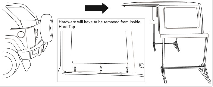
1. Remove the Hard Top (as per manufacturer's instructions) and place onto a stable safe working area.
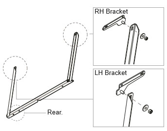
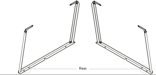
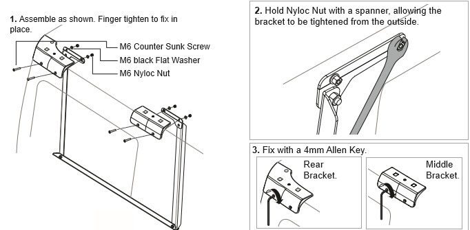
2A Assemble the support struts as shown. Finger tighten. Check part ID to make left and right side supports.
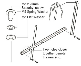
2B Attach item 12 to the arms as shown, using and M8 washer and M8 and Nyloc nut. Finger tighten.
3. Repeat process for opposing strut.
4. Align the REAR bracket with the REAR of the Hard Top. Line the bracket flush with the contour of the Hard Top as shown.
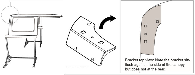
5. With bracket aligned, spot mark the bracket position as shown. It is important to be accurate when marking. Always mark the centre of the hole.
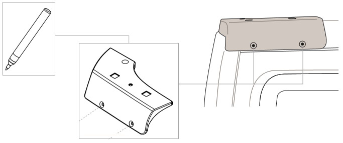
7. With the Centre Bracket aligned, spot mark the bracket position as shown.
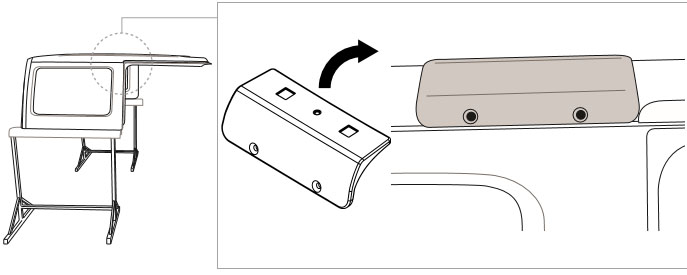
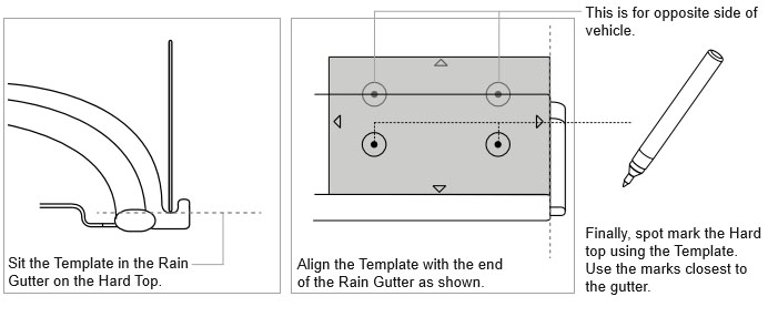
8a Place the front bracket Template onto the Hard Top as shown (template as suppliment)
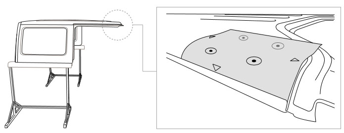
8b With the front bracket template placed onto the Hard Top, align as shown and mark spot.
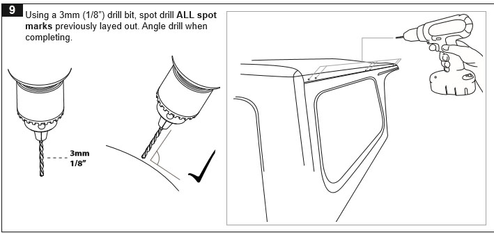
9. Use a 3mm (1/8") drill bit, spot drill All Spot Marks previously laid out. Angle drill when completing.
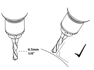
10. Using a 6.5mm (1/4") drill bit, drill out the Rear and Middle spot drilled sections on the Hard Top.
11. Front Holes Only: Using a 6-18mm step drill bit, open out the front spot holes as shown.
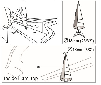
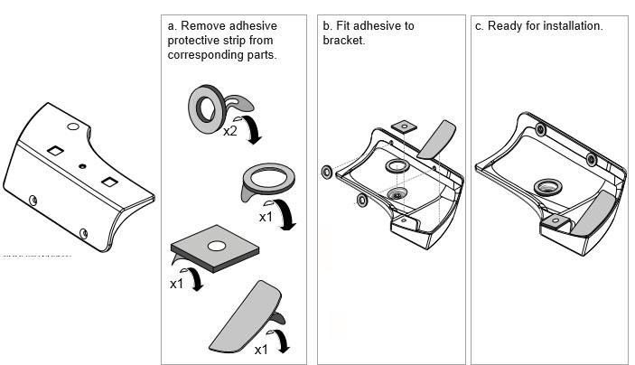
12. With relation to the Front Bracket, take corresponding foam pads and remove the protective strip as shown. Fit to bracket.
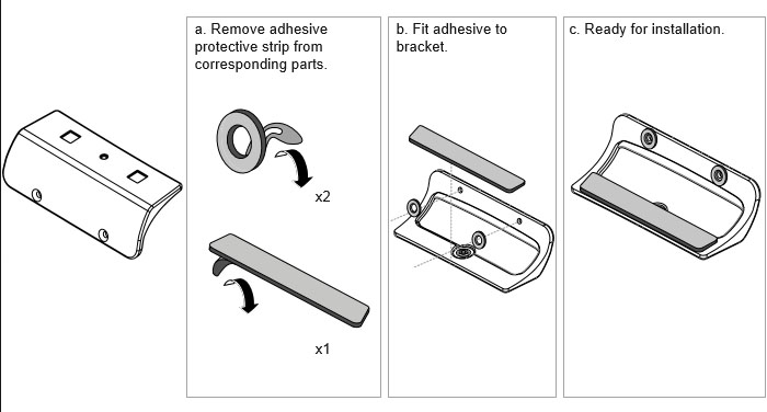
13. With relation to the Centre bracket, take corresponding foam pads and remove the protective strip as shown. Fit to bracket.
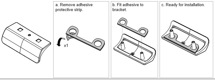
14. With relation to the rear bracket, take corresponding foam pads and remove the protective strip as shown. Fit to bracket.
15. With assistance to hold the support strut in place, set the assembly on the inside of the Hard Top as shown.
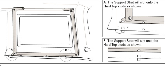
16. With assistance to hold the support strut in place, move to the outside of the Hard Top. Place the REAR bracket in place. Insert M6 counter sink screws, fastening from the inside with M6 black flat washers and M6 Nyloc nuts. Hold the nyloc nuts in place with a 10mm spanner. Tighten from the outside with a 4m allen key. Repeat this process for the Centre bracket.
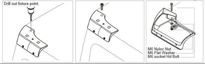
17. With rear bracket now secure, drill out the top fixture point with a 6.5mm (1/4") bit. Use an M6 socket HD Bolt with O ring, and M6 flat washer and an MC nyloc nut to fix the bracket.
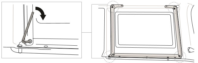
18. Tighten supports with a 5mm allen key. Top of supports will require a 13mm spanner.
19. Place the FRONT bracket onto the Hard Top. Using the black M6x20 dome head setscrews, M6 spring washers, and M6 Flat Washers, attach the Backing plate and material support to the Front Bracket from inside the Hard Top as shown. Tighten with a 4mm allen key.
20. Move to the centre of the vehicle as shown.
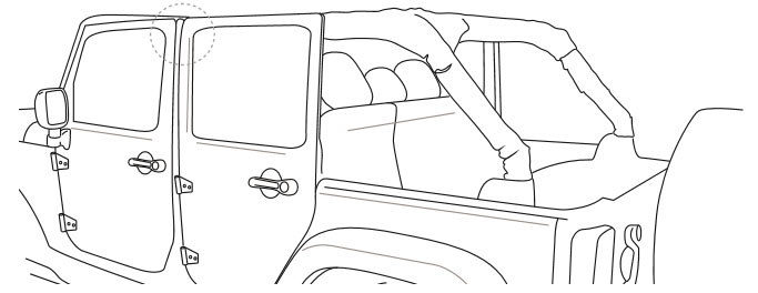
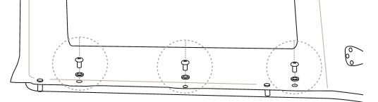
21. Locate zipper concealing the Jeep's bracket fixture point.
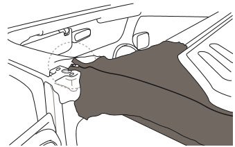
22. Unzip, revealing fixture point.
23. Remove with 13mm socket wrench.
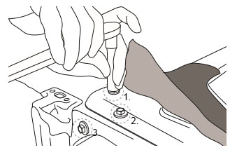
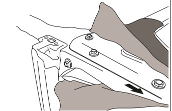
24. Place Jeep bracket onto vehicle as shown.
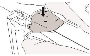
25. Replace hardware with a 13mm (1/2") socket wrench.
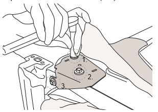
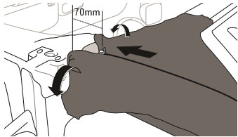
26. Re-zip protective cover to 70mm from the top. Tuck any excess material under and out of the way.
27. Place the Hard Top back onto the Jeep (refer to manufacturer's instructions). Replace the hardware removed in step 1 on both sides of the inner Hard Top.
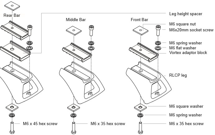
28. Setup for 3 Vortex Crossbars as follows.
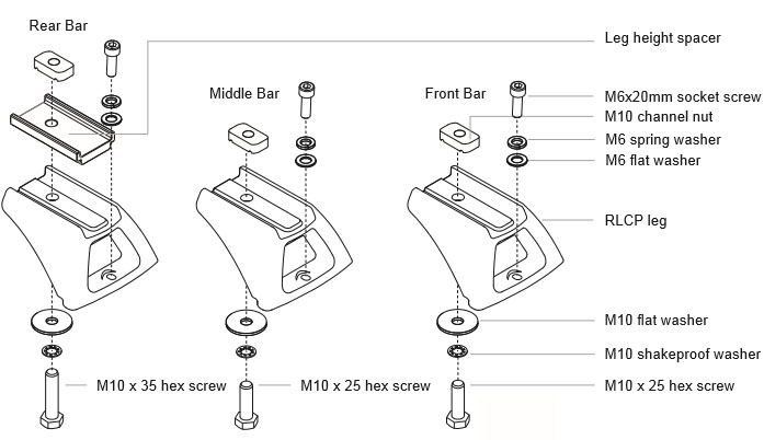
Setup heavy duty crossbars as follows.
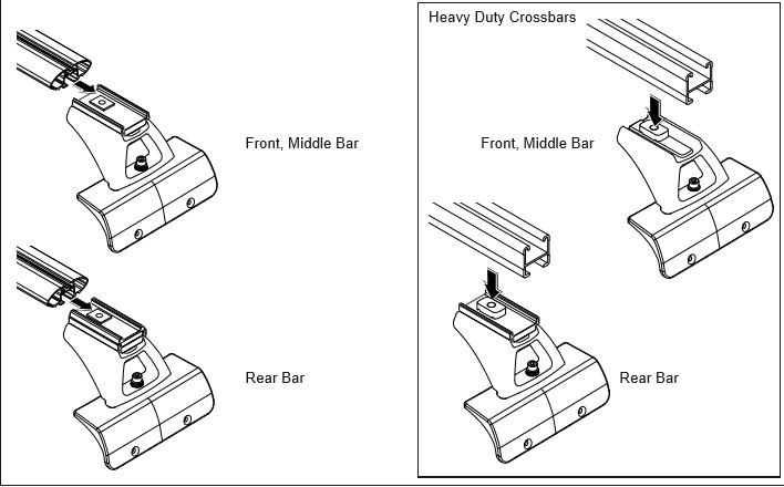
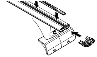
30. Attach Vortex Crossbars
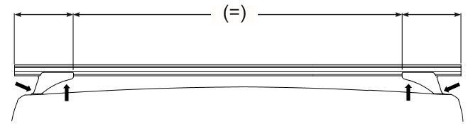
31. Adjust crossbar overhang to be equal on both sides. Tighten M6 crossbar bolts to 3-4NM 2-3lb/ft.
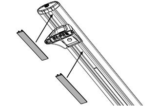
32. Insert vortex rubber and end caps into all crossbars.
33. Measure the under bar slot length each side of the leg. Cut under bar strips to fill the gaps.
Note: Re-check all fasteners are secure.