 FREE 1 to 3-Day Delivery on Orders $149+ Details

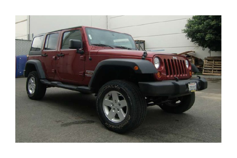
How to Install ReadyLIFT 4 in. Super Flex Short Arm Lift Kit (07-18 Wrangler JK) on your Jeep Wrangler
Safety Warning: Suspension systems or components that enhance the on and off-road performance of your vehicle may cause it to handle differently than it did from the factory. Extreme care must be used to prevent loss of control or vehicle rollover during abrupt maneuvers. Always operate your vehicle at reduced speeds to ensure your ability to con-trol your vehicle under all driving conditions. Failure to drive safely may result in serious injury or death to driver and passengers. Driver and passengers must ALWAYS wear your seat belts, avoid quick sharp turns and other sudden ma-neuvers. ReadyLIFT Suspension Inc. does not recommend the combined use of suspension lifts, body lifts, or other lift-ing devices. You should never operate your vehicle under the influence of alcohol or drugs. Constant maintenance is required to keep your vehicle safe. Thoroughly inspect your vehicle before and after every off-road use.
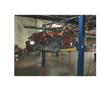
Installation Warning: All steps and procedures described in these instructions were performed while the vehicle was properly supported on a two post vehicle lift with safety jacks. Use caution during all disassembly and assembly steps to insure suspension components are not over extended causing damage to any vehicle components and parts included in this kit. Included instructions are guidelines only for recommended procedures and are not meant to be definitive. In-staller is responsible to insure a safe and controllable vehicle after performing modifications.
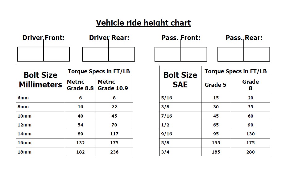
ReadyLIFT Suspension Inc. recommends the use of an OE Service Manual for model/year of vehicle when disassembly and assembly of factory and related components. Unless otherwise specified, tighten all bolts and fasteners to standard torque specifications listed within the OE Service Manual, or as referenced in the torque specification list provided in these instructions.
Suspension components that use rubber or urethane bushings should be tightened with the vehicle at normal ride height. This will prevent premature wear or failure of the bushing and maintain ride comfort. Larger tire and wheel combinations may increase leverage on suspension, steering, and related components. Due to payload options and ini-tial ride height variances, the amount of lift is a base figure. Final ride height dimensions may vary in accordance to original vehicle ride height. Always measure the vehicle ride height prior to beginning installation.
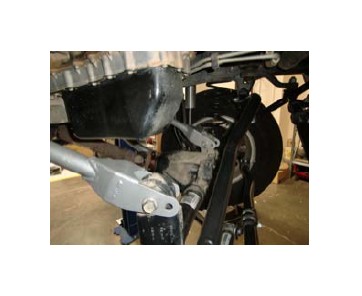
ReadyLIFT® arms come pre set for a 4” lift kit. Depending on your suspension configuration you may need to adjust accordingly to fit your application. It is the responsibility of the installer to insure the driveline angles are correct and spin freely.
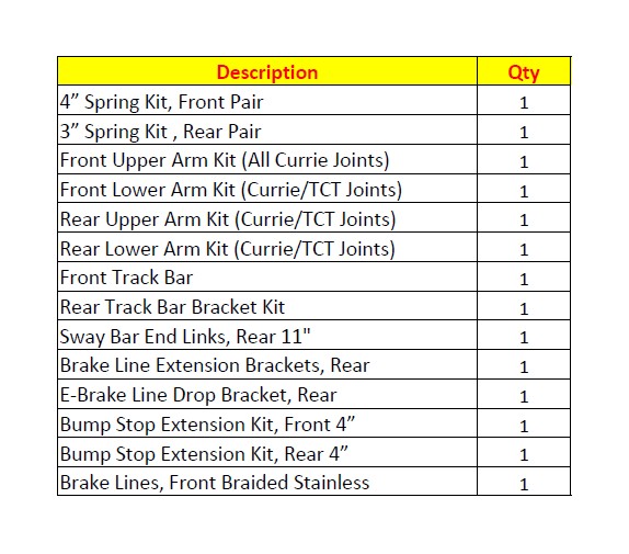
The Bill of Materials represents the component contents of this kit. All hardware is of the highest grade and the components are manufactured to exacting specifications for a trouble free installation. Use the attached torque specifications chart when final tightening of the nut and bolts are done.
These instructions are to be used as a guideline for all 49-6600 series kit’s. The instructions that follow are for the Master / Complete kit. Please read instructions thoroughly before starting install to familiarize yourself with the components in your kit. NOT ALL PART’S in these instructions will be included if you are using a 49-6600 Base kit. Note: We recommend the use of an exhaust down pipe extension, to be purchased separately.
1. Read all instructions first.
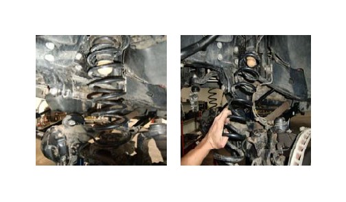
2. Lift the vehicle and remove the tires. Support the axles.
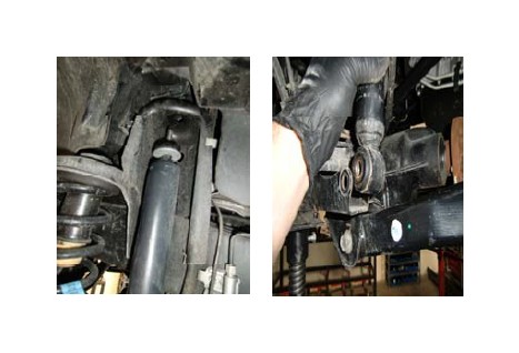
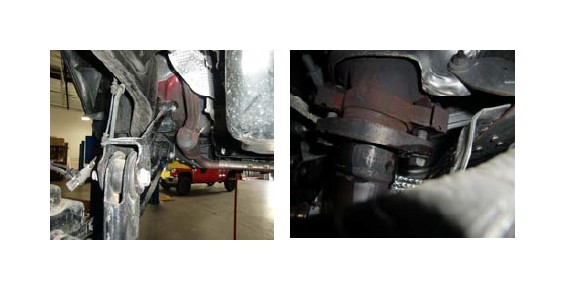
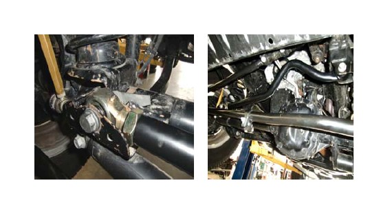
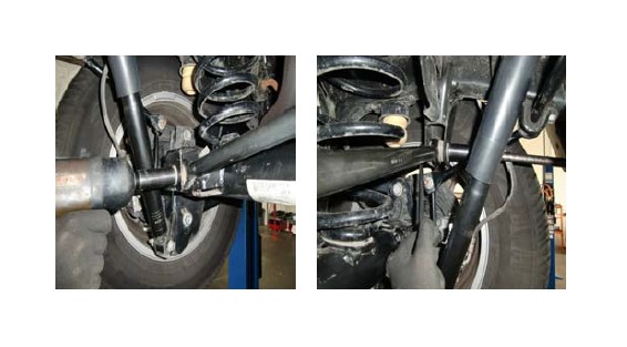
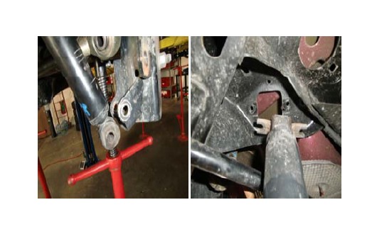
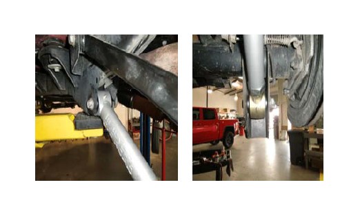
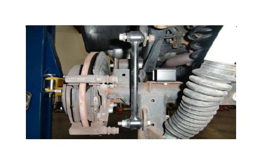
3. With the vehicle properly supported locate the front track bar.
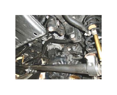
4. Remove the track bar from the frame.
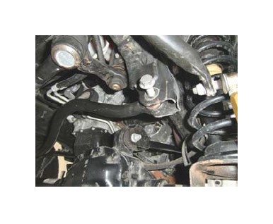
5. Next, unbolt the track bar from the axle and remove from vehicle.
6. Unbolt and remove the sway bar end links from vehicle.
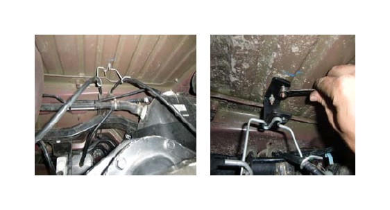
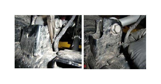
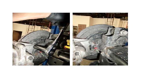
7. Unbolt and dislodge the brake line brackets from the axle.
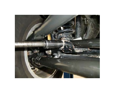
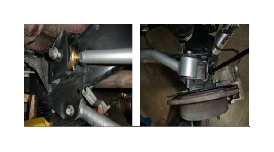
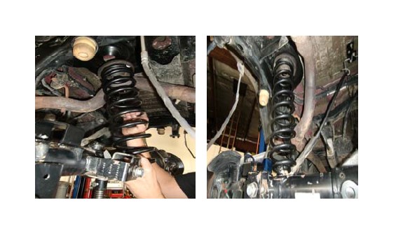
8. Remove the stock shocks off of the vehicle (front & rear).
9. Unhook the differential vent line from the frame.
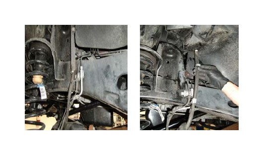
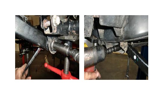
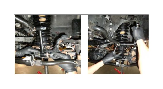
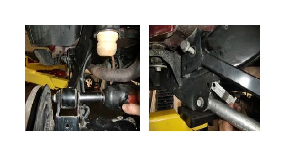
10. Unbolt the tie-rod from the spindle.
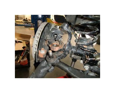
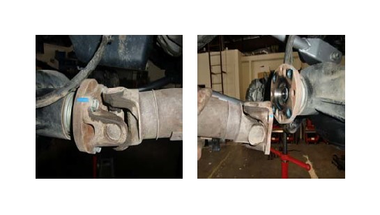
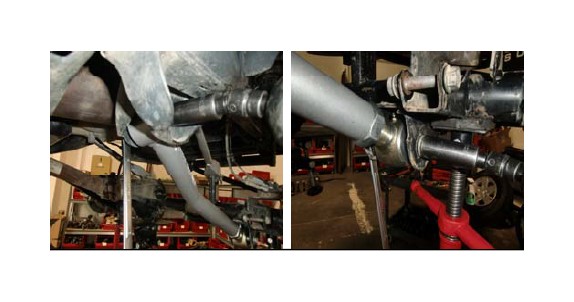
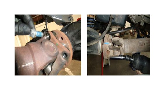
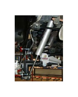
11. Mark drive shaft for re-alignment during reassembly. Unbolt the drive shaft from the front differential.
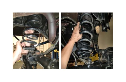
12. Lower the axle and remove the coil springs.
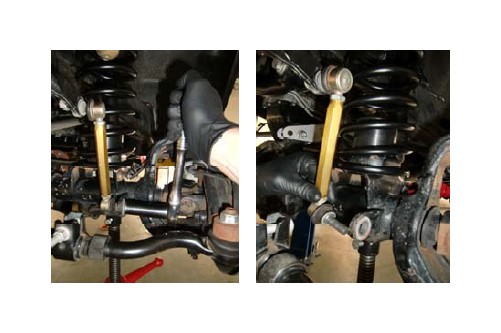
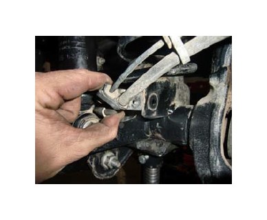
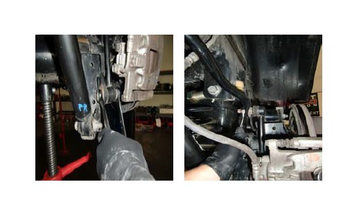
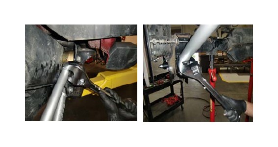
13. Unbolt drivers side front upper arm at the axle.
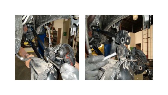
14. Unbolt drivers side front upper arm from the frame.
15. Install the new arm into frame and onto axle, then tighten down. You may need to un-bolt the passenger side to fit the Driver side arm due to length differences from stock arm to ReadyLIFT® arm.
16. On passengers side, unbolt the header from the exhaust. Use some type of thread lubricant to help free rusted exhaust.
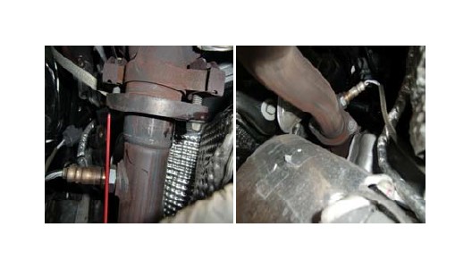
17. Unbolt the passenger side upper arm and install the new arm. You may need to flex the exhaust to remove the upper arm bolt. Tighten the upper arms on both sides. Then reinstall the bolts for the exhaust.
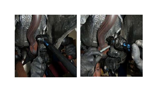
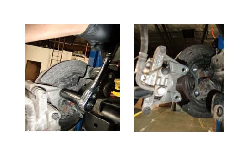
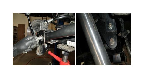
18. Unbolt and remove the both L & R lower arms from the vehicle. Support the differential to prevent axle roll.
19. Install the new front lower arm on both sides of vehicle and tighten. The adjustable end should be mounted at the axle and the bend should Point to the center of the vehicle also badges should be legible.
20. Center, mark and drill 7/16 hole.
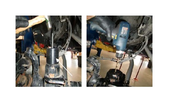
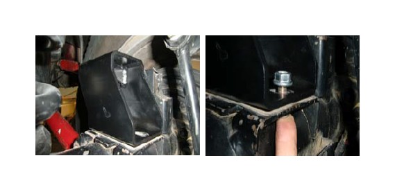
21. Slip bump pad extension in the coil spring and install as complete assembly. Then tighten the bump extension bolt down using the hardware provided.
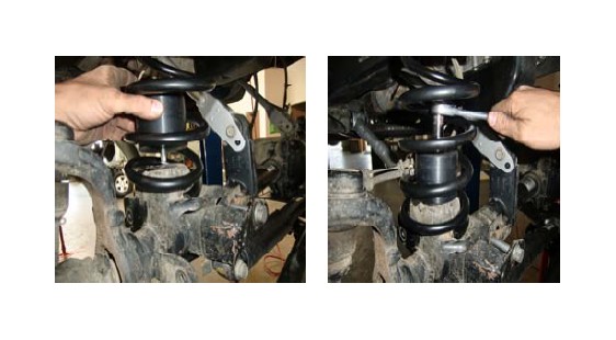
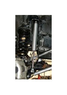
22. Install new extended length shocks.
23. Install the OEM Rear Sway Bar End links on the front of Vehicle.
24. Re-install the front drive shaft to the differential using Lock- tight. Re-align marks to insure proper drive shaft alignment.
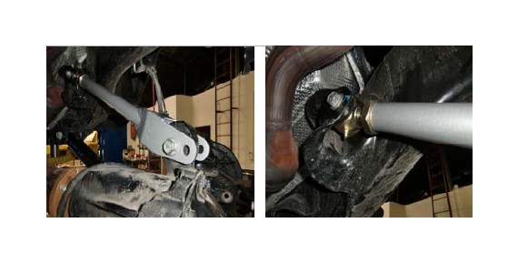
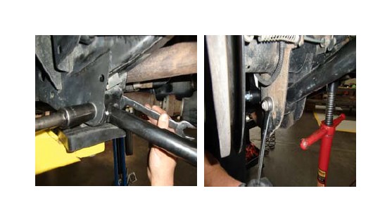
25. Install New track bar and torque down. Also re-install the tie- rod end and torque down.
26. Unbolt the brake line and remove from vehicle. Remove old bracket and install the new Bracket. Bolt the bracket to the frame first, then install the line through bracket. Finish with the push on clip to hold brake line.
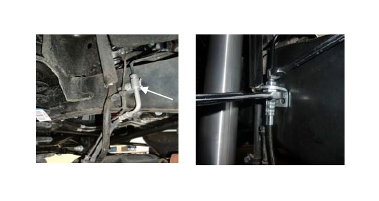
27. Brake lines are different for a pass. side & driver side, not universal. The bend goes toward the wheel. Route ABS wire properly. You must bleed brakes before the vehicle is driven.
28. Unbolt rear brake line bracket from bottom of the cab. Bolt the stock bracket to the drop bracket with supplied hardware.
29. Unbolt and remove the rear track bar. Support the rear axle.
30. Unbolt the rear sway bar end links and remove.
31. Unbolt and remove rear brake caliper and hang caliper out of the way.
32. Remove the rear shocks.
33. Remove ABS line clips from holes in rear axle. Put the back clip into the front hole.
34. Lower the rear axle and remove the springs.
35. Unbolt the rear lower arms and remove.
36. Install new lower arms and tighten down. The adjustable end should be installed on axle side.
37. Unbolt both rear upper arms and remove from vehicle.
38. Install the new rear upper arms. Adjustable ends should be installed on frame side and the zerk fittings up on axle side.
39. Install new bump with supplied hardware. Bump stop pad should be leaning towards front of vehicle.
40. Install new coil with factory rubber boot on top.
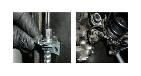
41. Unbolt the brake line brackets from the frame and install the brake line drop brackets with supplied hardware.
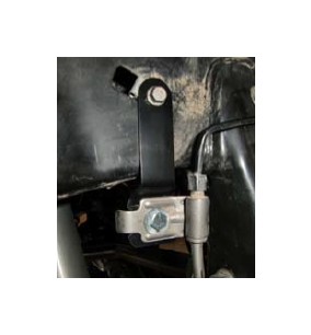
42. Install rear track bar extension bracket with provided hardware and spacers.
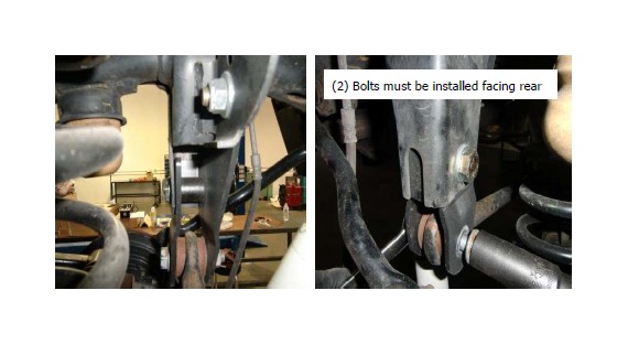
43. Install track bar into the frame pocket and axle mount.
44. Re-install the brake calipers and torque.
45. Install the extended rear 11” sway bar end links L & R with Supplied hardware. The heads of the bolts should face to the inside of the vehicle.
46. Install the extended rear shocks.
47. Make sure to tighten all jam nuts on the upper and lower arms on the front and the rear of the vehicle including tracking bars.
48. Re-check that all parts were installed properly and tightened. Put the tires on and lower the vehicle to the ground. Loosen and retighten the front upper arms at axle to allow upper arm to settle into ride position.
49. The install is complete and the VEHICLE MUST BE ALIGNED and brakes checked before driving.
Final Checks & Adjustments
Post Installation Warnings: Once the vehicle is lowered to the ground, check all parts which have rubber or urethane components to insure proper torque. Torque wheels to factory specs. Move vehicle backwards and forwards a short distance to allow suspension components to adjust. Turn the front wheels completely left then right and verify adequate tire, wheel, brake line, and ABS wire clearance. Test and inspect steering, brake and suspension components for tightness and proper operation. In-spect brakes hoses and ABS lines for adequate slack at full extension. Failure to perform the post in-spection checks may result in vehicle component damage and/or personal injury or death to driver and/ or passengers. Test drive vehicle and re-check the torque of all fasteners and re-torque wheels on vehi-cle. Re-adjust headlamps.
Vehicle Handling Warning: Vehicles with larger tires and wheels will handle differently than stock vehicles. Take time to familiarize yourself with the handling of your vehicle.
Wheel Alignment/Headlamp Adjustment:
It is necessary to have a proper and professional wheel alignment performed by a certified alignment technician. Align the vehicle to factory specifications. It is recommended that your vehicle alignment be checked after any off-road driving. In addition to your vehicle alignment, for your safety and others, it is necessary to check and adjust your vehicle head-lamps for proper aim and alignment
Vehicle Re-Torque and Safety Inspection:
Upon completion of all services and adjustments performed on your vehicle, and within 50 miles of driv-ing, check to ensure all fasteners and hardware are properly torqued to specification as noted in the vehicles factory service manual or the torque chart included.

