FREE 1 to 3-Day Delivery on Orders $149+ Details

How to Install Pro Comp ES3000 Series Suspension Rear Shock for 3-4 in. Lift on your Wrangler
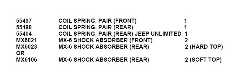
FOLLOWING PARTS ARE USED IN CONJUNCTION WITH THIS KIT. THEY ARE PACKAGED AND MUST BE ORDERED SEPARATELY.
Introduction:
♦ This installation requires a professional mechanic!
♦ We recommend that you have access to a JEEP service manual for your vehicle to assist in the disassembly and reassembly of your vehicle. It contains a wealth of detailed information.
♦ Ensure that your work space is of adequate size and the work surface is level. Place the vehicle in neutral. Place your floor jack under the front cross member and raise vehicle. Place jack stands under the frame rails behind the front wheel wells and lower the frame onto the stands. Remove the jack and place the vehicle back in gear, set the emergency brake, and place blocks both in front and behind the rear wheels.
♦ Prior to installation, carefully inspect the vehicle’s steering and driveline systems paying close attention to the tie rod ends, ball joints, wheel bearing preload, pitman and idler arm. Additionally, check steering-to-frame and suspension-to-frame attaching points for stress cracks. The overall vehicle must be in excellent working condition. Repair or replace all worn or damaged parts!
♦ Read the instructions carefully and study the illustrations before attempting installation! You may save yourself a lot of extra work.
♦ Check the parts and hardware against the parts list to assure that your kit is complete. Separating parts according to the areas where they will be used and placing the hardware with the brackets before you begin will save installation time.
♦ Check the special equipment list and ensure the availability of these tools.
♦ Secure and properly block vehicle prior to beginning installation.
♦ ALWAYS wear safety glasses when using power tools or working under the vehicle!
♦ Use caution when cutting is required under the vehicle. The factory undercoating is flammable. Take appropriate precautions. Have a fire extinguisher close at hand.
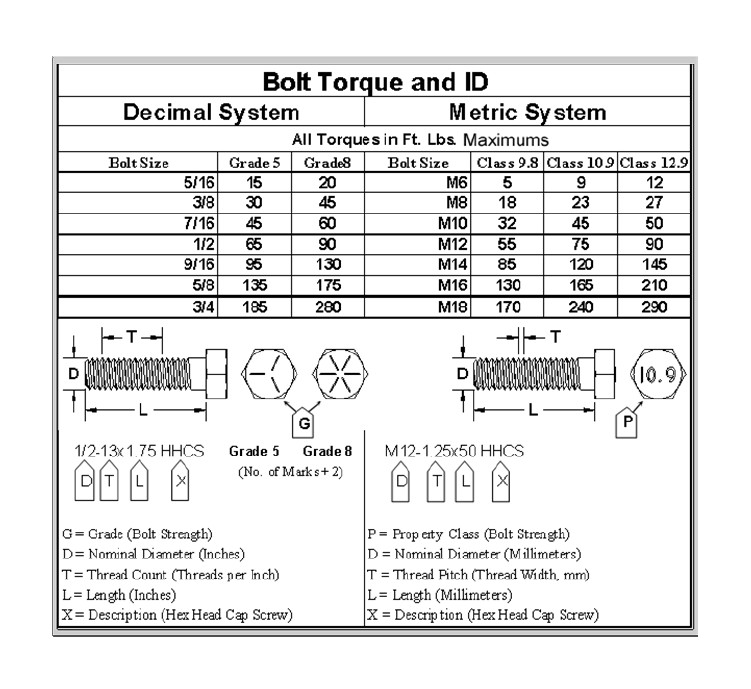
♦ Foot pound torque readings are listed on the Torque Specifications chart at the end of the instructions. These are to be used unless specifically directed otherwise. Apply thread lock retaining compound where specified.
♦ Please note that while every effort is made to ensure that the installation of your Pro Comp lift kit is a positive experience, variations in construction and assembly in the vehicle manufacturing process will virtually ensure that some parts may seem difficult to install. Additionally, the current trend in manufacturing of vehicles results in a frame that is highly flexible and may shift slightly on disassembly prior to installation. The use of pry bars and tapered punches for alignment is considered normal and usually does not indicate a faulty product. However, if you are uncertain about some aspect of the installation process, please feel free to call our tech support department at the number listed on the cover page. We do not recommend that you modify the Pro Comp parts in any way as this will void any warranty expressed or implied by the Pro Comp Suspension company.
Please Note:
BEFORE YOU BEGIN:
♦ Read the instructions and study the illustrations before attempting installation. Separating the parts according to the areas where they will be used and placing the hardware with the brackets before you begin will save installation time.
♦ Check the parts and hardware against the parts list to assure that your kit is complete. ♦ Always wear safety glasses when using power tools.
♦ Always use new cotter pins (these items are not supplied) when replacing them.
♦ Front end and headlight realignment is necessary.
♦ Speedometer and ABS recalibration will be necessary if larger tires (10% more than stock diameter) are installed
♦ Due to differences in manufacturing, dimensions and inflated measurements, tire and wheel combinations should be test fit prior to installation. Tire and wheel choice is crucial in assuring proper fit, performance, and the safety of your Pro Comp equipped vehicle. For this application, we recommend a wheel not to exceed 10” in width with a minimum backspacing of 3.25” must be used. Additionally, a quality tire of radial design, not exceeding 33” tall X 12.5” wide is also recommended. Please note that the use of a 33” X 12.5” tire may require fender modification. Violation of these recommendations will not be endorsed as acceptable by Pro Comp Suspension and will void any and all warranties either written or implied.
Installation:
1. Prior to installing this kit, with the vehicle on the ground. Measure the height of your vehicle . This measurement can be recorded from the center of the wheel, straight up to the top of the inner fender lip. Record the measurements below.
LF: _______________ RF: _______________
LR: _______________ RR: _______________
DISASSEMBLY - FRONT
1. Ensure that your work space is of adequate size and the work surface is level. Place the vehicle in neutral. Place your floor jack under the front cross member and raise vehicle. Place jack stands under the frame rails behind the front wheel wells and lower the frame onto the stands. Remove the jack and place the vehicle back in gear, set the emergency brake, and place blocks both in front of and behind the rear wheels. Remove the wheels.
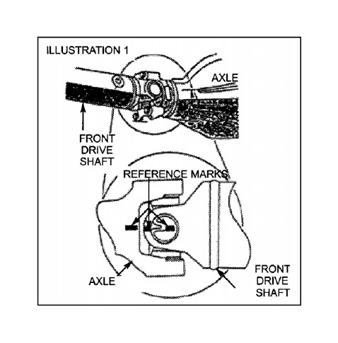
2. Place reference marks (as shown in ILLUSTRATION 1) on front drive shaft and axle. Disconnect the front drive shaft from axle.
NOTE: If vehicle is equipped with ABS brakes remove sensor wire from the inboard side of the lower control arm.
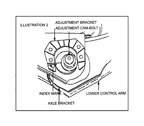
3. Locate adjustment cam bolts, positioned on front of existing lower control arms. Make and index mark as shown in ILLUSTRATION 2, for installation reference. Remove lower control arms.
4. Remove front shock absorbers. Disconnect the stabilizer bar link at the axle.
5. Lower axle until coil spring is free from upper mount. Remove coil spring retainer bolt and remove the coil spring.
INSTALLATION - FRONT
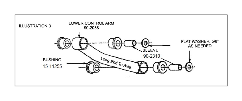
1. Insert the bushings (15-11255) and sleeves (90-2310), using a thin layer of lubricant, into the new lower control arms (90-2058) as shown in ILLUSTRATION 3.
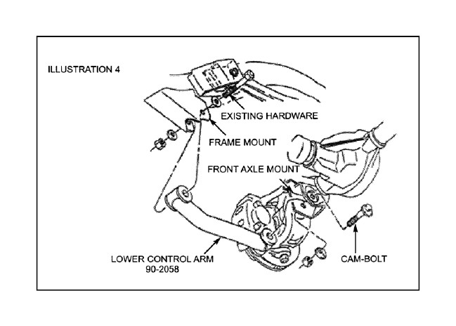
2. Position the lower control arms in the front and rear brackets and install using the existing hardware as shown in ILLUSTRATION 4. Adjust the cambolt to the index mark. Torque lower cam-bolt nut to 85 ft./lbs. and upper frame bracket nut to 130 ft./lbs.
NOTE: If you vehicle is equipped with ABS brakes reinstall sensor wire to inboard side of gusset located on lower control arm.
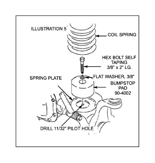
3. Mark center of lower coil spring pad. Using a 11/32” diameter drill bit, drill a pilot hole in the previously marked area.
4. Temporally zip tie the new bump stop pad (90-4002) inside the new front coil spring (55497). It will be installed later.
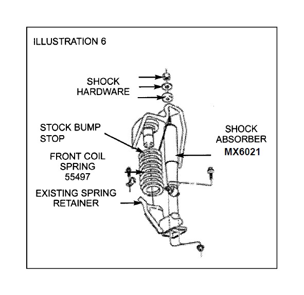
5. Position new front coil spring (55497) on axle pad. Reinstall coil spring retainer and bolt. Torque to 16 ft./lbs. Raise the axle into position until coil spring seats in upper mount, then raise axle another 2”. Install new longer shock absorbers (MX6021) as shown in ILLUSTRATION 6. Torque upper shock nuts to 17 ft./lbs. and lower nuts to 20 ft./lbs.
6. Install new bump stop pad (90-4002) as shown in ILLUSTRATION 5. Install, using 3/8” self-tapping hardware provided. Torque to 20 ft./lbs.
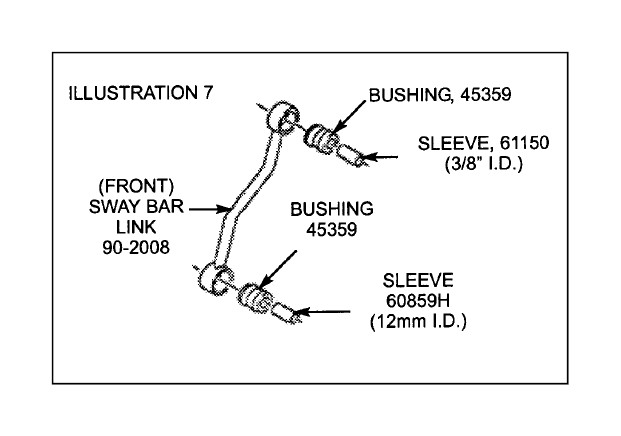
7. Install hour glass bushing 45359 and 61150-TOP sleeve in the top and 45359 bushing and 60859H-BOTTOM sleeve in the bottom of the 90-2008 as shown in ILLUSTRATION 7.
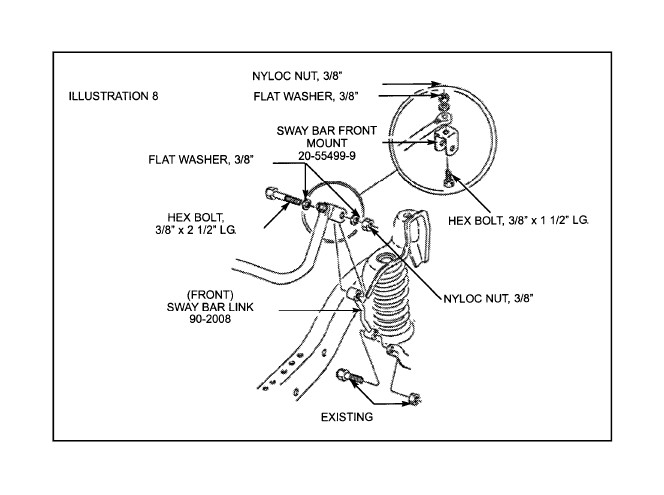
8. Mount the sway bar front mount bracket (90-1010) to the sway bar using the 3/8” hardware provided. Attach sway bar link (90- 2008) using provided hardware as shown in ILLUSTRATION 8. Torque to 30 ft./lbs.
9. Remove the (4) 6mm bolts that fasten the transfer case pivot bracket to the floor pan. This can be accessed by lifting the carpet on drivers side of the vehicle. Slide pivot bracket form pivot rod and set aside.
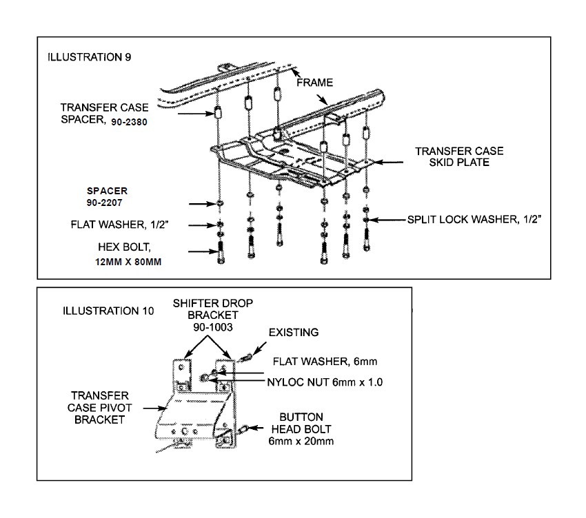
10. Support the transfer case skid plate. The transfer case and transmission are supported by the skid plate. Before removing the skid plate ensure that the transmission in properly supported. Remove the (6) bolts connecting the skid plate to the frame. Reinstall transfer case skid plate with transfer case spacers (90- 2382), bottom spacers (90-2207) and supplied 12MM X 80MM hardware as shown in ILLUSTRATION 9. Torque bolts to 55 ft./lbs.
11. Install shifter drop bracket (90-1003) to pivot bracket using 6mm hardware provided. Install assembly into the existing mounting location using hardware previously removed. See ILLUSTRATION 10.
NOTE: You may need to adjust the 4wd shifter rod to engage 4wd.
NOTE: It is very important that the shifter pivot rod protrudes through the self-aligning bearing on the pivot bracket approximately 3/8”. By bending the opposite bracket on the Transfer Case, you can easily achieve this. 12. Reconnect the front drive shaft to the axle using the reference marks as guides. Refer back to ILLUSTRATION 1 if necessary.
DISASSEMBLY– REAR
1. Raise the rear of the vehicle, support frame with jack stands and remove rear wheels and tires.
2. Support the rear axle.
3. Remove existing rear shocks.
4. Locate and remove rear stabilizer bar links.
5. Loosen the rear lower control arms.
6. Remove the upper track bar bolt on the passenger side of the jeep.
7. Lower rear axle until coil springs are free from upper seat. Remove coil springs.
8. Remove the lower control arms.
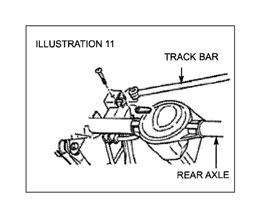
9. Disconnect lower track bar bolt and bar as shown in ILLUSTRATION 11.
INSTALLATION– REAR
1. Position rear lower control arms (90- 2058) into existing front and rear mounting brackets and install using hardware previously removed. Do not tighten at this time.
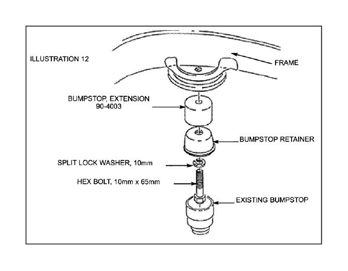
2. Install new rear bump stop extension (90-4003) using the supplied 10mm hardware as shown in ILLUSTRATION 12. Torque to 27 ft./lbs.
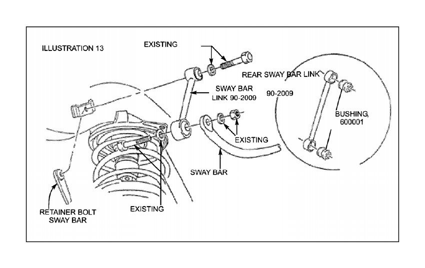
3. Assemble sway bar links 90-2009 using 60001 bushing and install as shown in ILLUSTRATION 13. When reinstalling existing stabilizer bar you must ensure that the bar is centered, equally spaced, over both side of differential housing. Fasten using existing hardware. Torque to 40 ft./lbs.
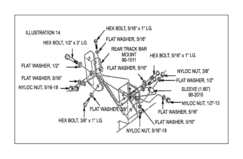
4. Referring to ILLUSTRATION 14 install rear track bar mount bracket (90-1011) using 1.60” sleeve (90-2010) and supplied hardware. Align the bracket so that it is 90 degrees to the axle tube, this will properly locate the axle under the truck. Torque existing track bar bracket bolt to 74 ft./lbs. Drill out the 3/8” hole at the three 5/16” hole locations using bracket as template.
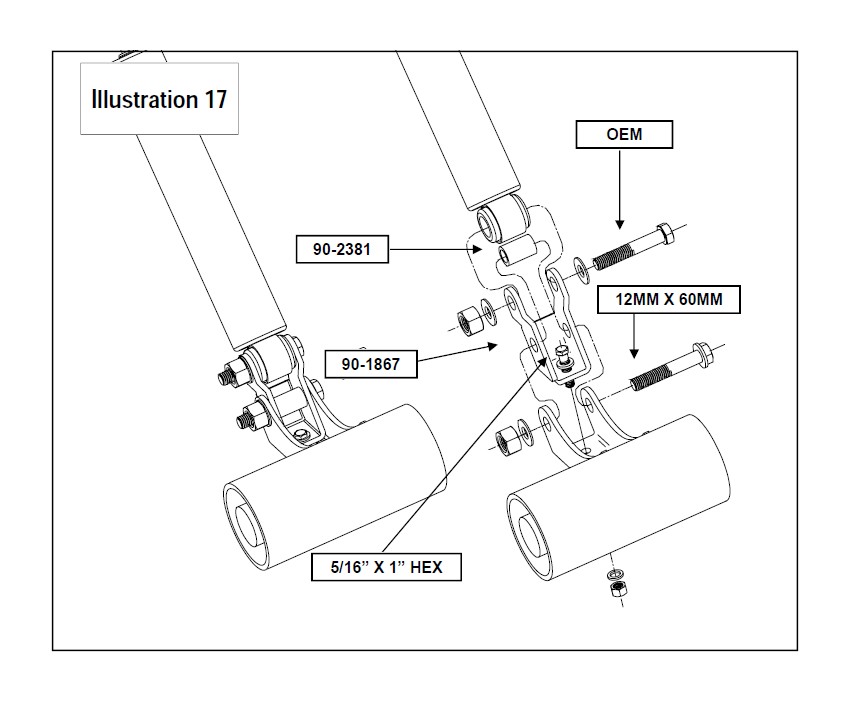
5. With the supplied 12MM X 60MM bolt, nut and washers from hardware pack 90-6293, install the shock relocation bracket 90-1867 to the rear axle.
6. Install the supplied 5/16” hard ware from pack 90-6293. the bolt head should be facing up. See Illustration 17.
7. Install new rear coil springs (55498 or 55404) and new longer shock absorbers (MX6023). At this time, torque existing lower control arm nuts to 130 ft./lbs.
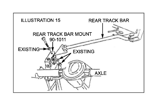
8. Attach track bar into new track bar mounting bracket, as shown in ILLUSTRATION 15 using hardware provided. Torque nut to 37 ft./lbs.
9. Cycle steering lock to lock and inspect steering, suspension and driveline systems for proper operation, tightness and adequate clearance. Recheck brake hose/fitting for leaks. Be sure all hoses are long enough.
10. Install the wheels and tires. Remove the jack stands and lower the vehicle.
CHECKS AND ADJUSTMENTS:
♦ Recheck all hardware for tightness after the first 100 miles.
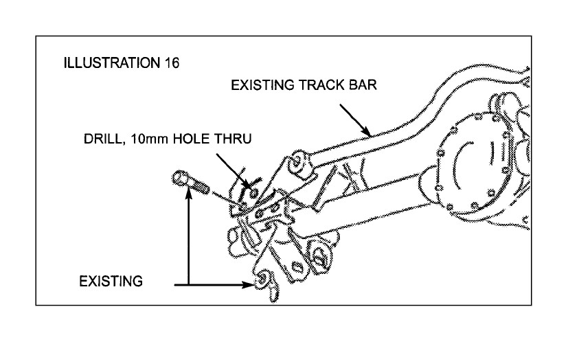
♦ To adjust location of front axle (side to side), place vehicle on a flat surface. Remove existing track bar bolt on passenger side of front axle tube. Center the axle under vehicle by turning steering wheel. Re-drill track bar mounting hole in the area shown in ILLUSTRATION 16, and install bolt. Use the track bar as a guide for exact hole location. NOTE: A JTB400 ADJUSTABLE TRACK BAR can also be used to center the axle and replace this procedure.
♦ Steering stops can be adjusted by use of spacers behind welded jam nuts, or be use of a secondary jam nut (not provided).
♦ Headlights should be adjusted.
♦ By hand rotate the front and rear drive shafts with suspension hanging. Depending on engine, transmission and differential combinations, it may be necessary to increase the drop on the transfer case if u-joint-to-yoke interference is found. This can be accomplished with the use of 1/2” flat washers (not provided). 1/4” additional drop is usually sufficient.
♦ Alignment of front wheels will be required, use factory specifications.
ADJUSTABLE TRACK BAR PN JTB 400 CAN BE USED IN PLACE OF THE EXISTING TRACK BAR.
Final notes:
1. If new tires are installed that are more than 10% taller than original tires, the speedometer must be recalibrated for the rear wheel anti-lock brake system to function properly. Contact an authorized GM dealer for details on recalibration.
2. With vehicle on the floor, cycle the steering from lock to lock and inspect the steering, suspension and driveline systems for proper operation, tightness and adequate clearance. Recheck brake hose/fittings for leaks. Be sure all brake lines are long enough for safe operation.
3. Have headlights readjusted to the proper settings.
4. Realign front end to factory specifications. Be sure the vehicle is at the desired ride height prior to realignment.
5. Recheck ALL fasteners at 100 miles to make sure they have not come loose. Due to the additional wear and tear created by larger tires and wheels, we recommend that you periodically check the suspension system and steering components to ensure service life and safe vehicle operation.