 FREE 1 to 3-Day Delivery on Orders $149+ Details

How to Install Pro Comp 4 in. Stage II Lift Kit w/ Shocks on your 1997-2006 Jeep Wrangler TJ

Introduction:
♦ This installation requires a professional mechanic!
♦ We recommend that you have access to a factory service manual for your vehicle to assist in the disassembly and reassembly of your vehicle. It contains a wealth of detailed information.
♦ Prior to installation, carefully inspect the vehicle’s steering and driveline systems paying close attention to the tie rod ends, ball joints, wheel bearing preload, pitman and idler arm. Additionally, check steering-to-frame and suspension-to-frame attaching points for stress cracks. The overall vehicle must be in excellent working condition. Repair or replace all worn or damaged parts!
♦ Read the instructions carefully and study the illustrations before attempting installation! You may save yourself a lot of extra work.
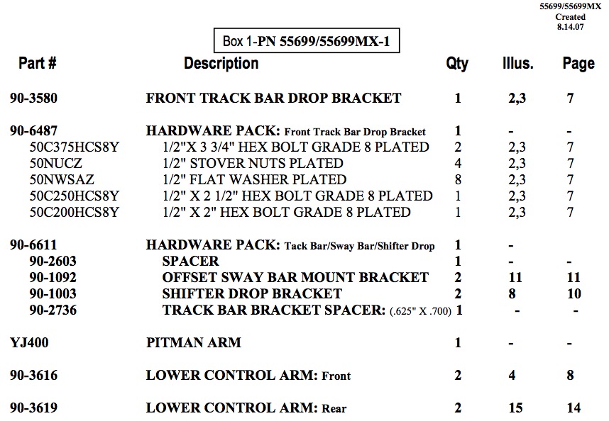
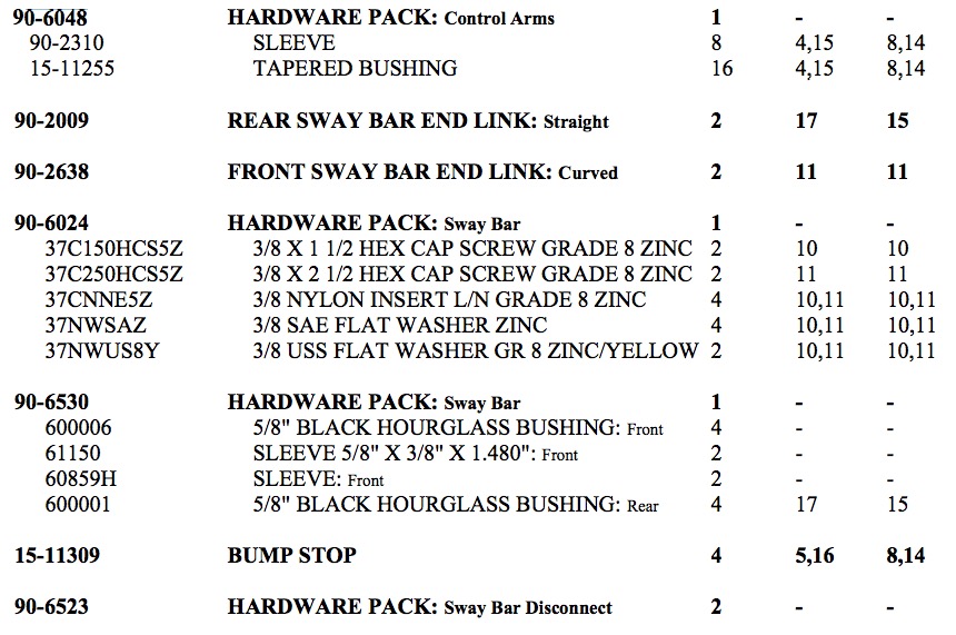
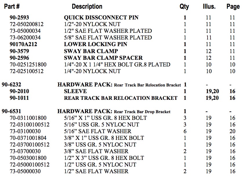
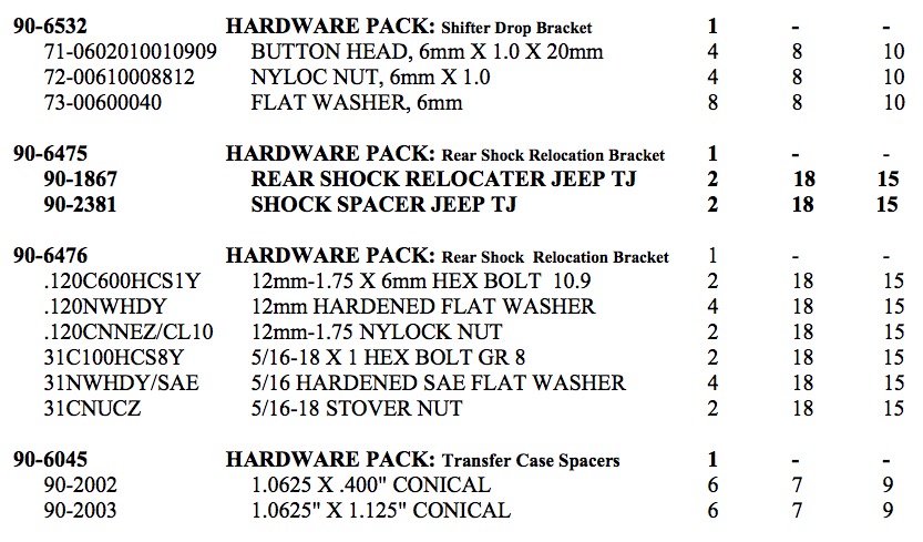
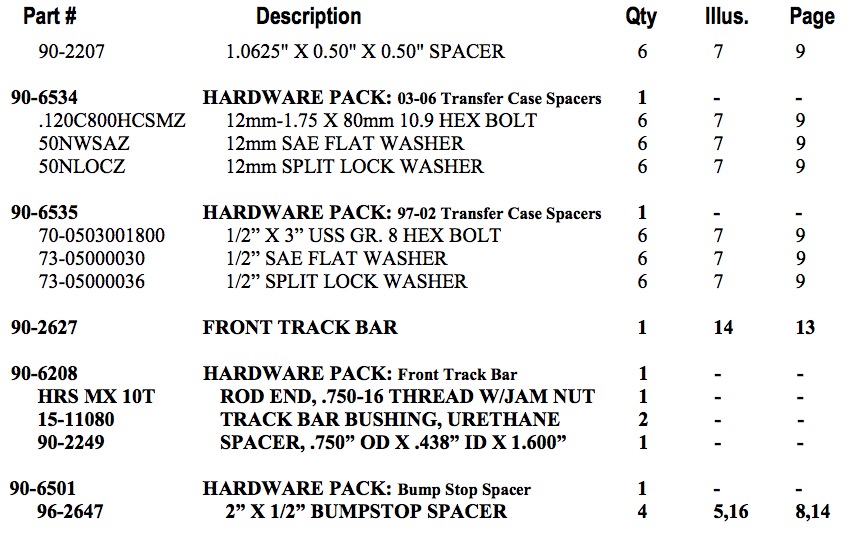
♦ Check the parts and hardware against the parts list to assure that your kit is complete. Separating parts according to the areas where they will be used and placing the hardware with the brackets before you begin will save installation time.
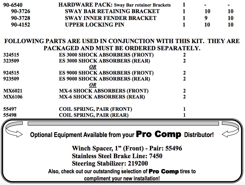
♦ Check the special equipment list and ensure the availability of these tools.
♦ Secure and properly block vehicle prior to beginning installation.
♦ ALWAYS wear safety glasses when using power tools or working under the vehicle!
♦ Use caution when cutting is required under the vehicle. The factory undercoating is flammable. Take appropriate precautions. Have a fire extinguisher close at hand.
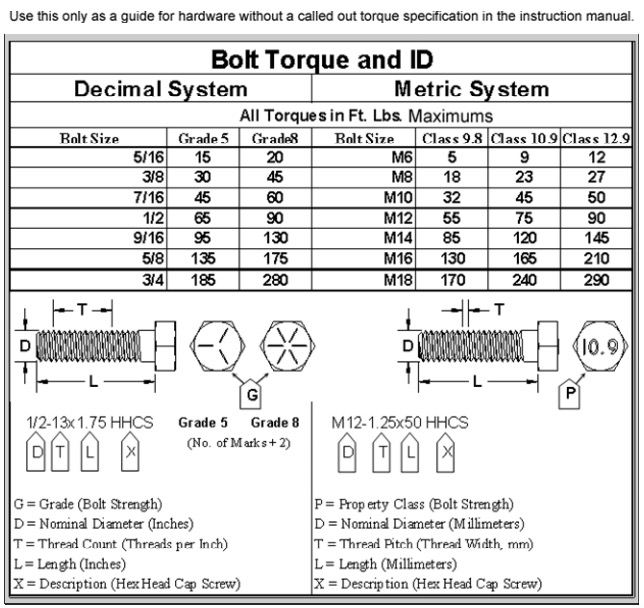
♦ Foot pound torque readings are listed on the Torque Specifications chart at the end of the instructions. These are to be used unless specifically directed otherwise. Apply thread lock retaining compound where specified.
♦ Please note that while every effort is made to ensure that the installation of your Pro Comp lift kit is a positive experience, variations in construction and assembly in the vehicle manufacturing process will virtually ensure that some parts may seem difficult to install. Additionally, the current trend in manufacturing of vehicles results in a frame that is highly flexible and may shift slightly on disassembly prior to installation. The use of pry bars and tapered punches for alignment is considered normal and usually does not indicate a faulty product. However, if you are uncertain about some aspect of the installation process, please feel free to call our tech support department at the number listed on the cover page. We do not recommend that you modify the Pro Comp parts in any way as this will void any warranty expressed or implied by the Pro Comp Suspension company.
PLEASE NOTE:
Due to differences in manufacturing, dimensions and inflated measurements, tire and wheel combinations should be test fit prior to installation. Tire and wheel choice is crucial in assuring proper fit, performance, and the safety of your Pro Comp equipped vehicle. For this application, a wheel not to exceed 8” in width with a minimum backspacing of 3.25” must be used. Additionally, a quality tire of radial design, not exceeding 33” tall X 12.5” wide is recommended. Please note that the use of a 33” X 12.5” tire may require fender modification. Violation of these recommendations will not be endorsed as acceptable by Pro Comp Suspension and will void any and all warranties either written or implied.
Installation Instructions:
DISASSEMBLY - FRONT
1. Position your vehicle on a smooth, flat, hard surface (i.e. concrete or asphalt). Block the rear tires and set the emergency brake.
2. Measure and record the distance from the center of each wheel to the top of its fender opening. Record below.

3. Place the vehicle in neutral. Place your floor jack under the front axle and raise the vehicle. Place jack stands under the frame rails and lower the frame onto the stands. Remove the jack and place the vehicle back in gear, set the emergency brake, and place blocks both in front and behind the rear wheels.
4. Remove the cotter pin and nut from the drag link at the pitman arm. Using the proper tool, disconnect the pitman arm from the drag link
5. Remove the nut and washer from the steering gear shaft. Remove pitman arm using a proper pitman arm removal tool.
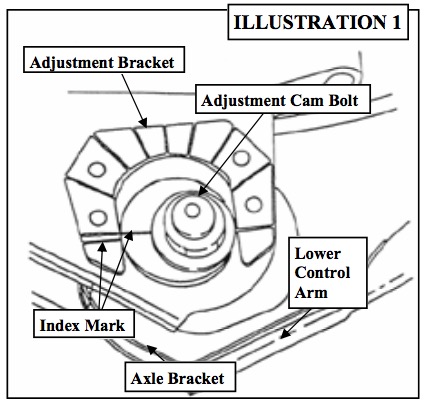
6. Locate adjustment cam bolts, positioned on front of existing lower control arms. Make and index mark as shown in ILLUSTRATION 1, for installation reference. Remove lower control arms.
NOTE: If vehicle is equipped with ABS brakes remove sensor wire from the inboard side of the lower control arm.
7. Unbolt and remove the front track bar from the vehicle.
8. Support the differential with your floor jack and remove the OE shock absorbers. It may be necessary to raise the differential housing slightly to facilitate their removal.
9. Disconnect the sway bar end links and remove from the vehicle.
10. Lower axle until coil spring is free from upper mount. Remove coil spring retainer bolt and remove the coil spring.
NOTE: Be sure to support the axle while the springs and shocks are removed.
11. Remove the OE bump stops from the bump stop mounting cup.
12. Unbolt the factory bump stop mounting cup from the frame. Save the hardware for reuse.
INSTALLATION - FRONT
13. Install the front track bar bracket (90- 3580) into the OE mounting position using the 1/2” X 2” bolt in the lower mounting hole. See ILLUSTRATION 2.
NOTE: If you have previously drilled the OE lower hole out to 5/8” install the provided sleeve (90-2736) in this hole.
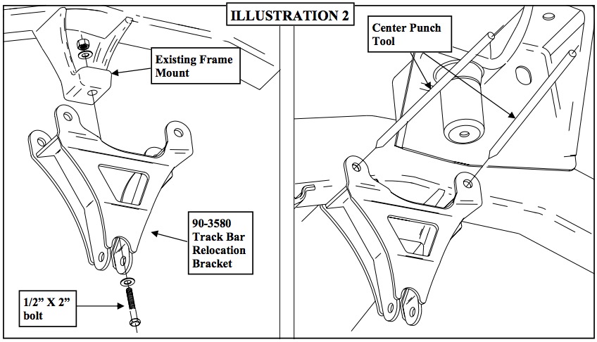
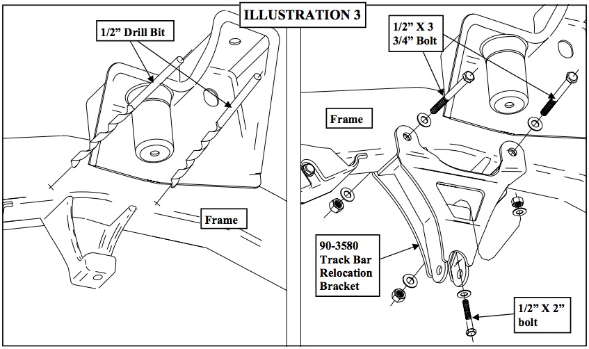
14. With the track bar bracket (90-3580) bolted in place, use the two upper holes as guide holes to mark the frame for drilling.
15. Center punch the previously made marks in the frame and drill out to 1/2”. See ILLUSTRATION 2 & 3.
16. Secure the upper holes of the bracket using the 1/2” X 3 3/4” bolts and hardware. See ILLUSTRATION 3.
17. Install the new pitman arm (YJ 400) using the OE retaining nut. Torque the retaining nut to 185 ft./lbs.
18. Reinstall the draglink onto the pitman arm. Torque to 60 ft./lbs.
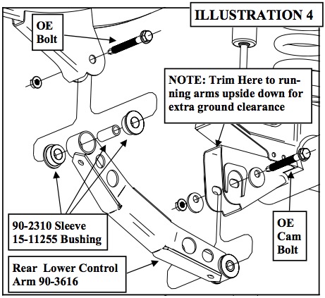
19. Insert the bushings (15-11255) and sleeves (90-2310), using a thin layer of lubricant, into the new lower control arms (90- 3616) as shown in ILLUSTRATION 4.
20. Position the lower control arms in the front and rear brackets and install using the existing hardware as shown in ILLUSTRATION 4. Adjust the cam bolt to the index mark. Torque lower cam-bolt nut to 85 ft./ lbs. and upper frame bracket nut to 130 ft./ lbs.
NOTE: The control arms can be installed upside down for additional ground clearance. The frame mounting pockets will need to be modified in order to accommodate this variation. See ILLUSTRATION 4.
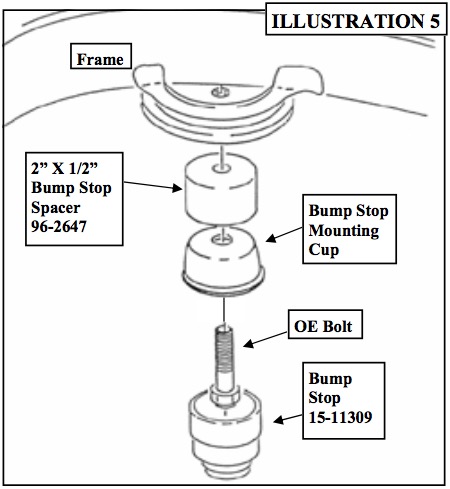
21. Bolt the bump stop cup to the frame using the previously removed OE bolt and the 1/2” X 2” bump stop spacer (96-2647). See ILLUSTRATION 5.
22. Install the supplied Bump stops (15- 11309) into the OE bump stop mounting cup.
NOTE: To properly seat the newly installed bump stops, carefully lower the weight of the vehicle onto the bump stops.
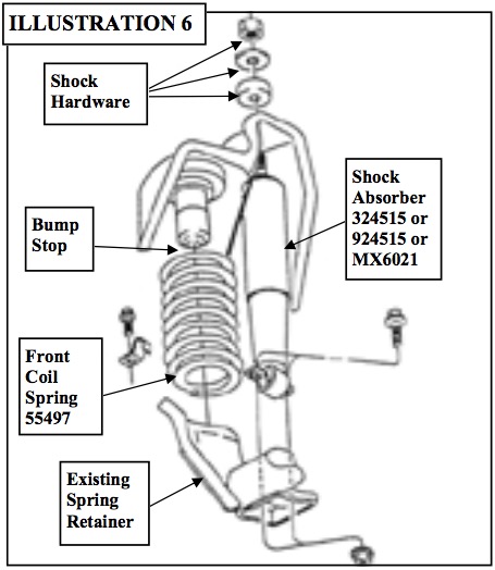
23. Position new front coil spring (55497) on axle pad. Reinstall coil spring retainer and bolt. Torque to 16 ft./lbs. Raise the axle into position until coil spring seats in upper mount, then raise axle another 2”. Install new longer shock absorbers (324515 or 924515 or MX6021) as shown in ILLUSTRATION 6. Torque upper shock nuts to 17 ft./lbs. and lower nuts to 20 ft./lbs.
24. Remove the (4) 6mm bolts that fasten the transfer case pivot bracket to the floor pan. This can be accessed by lifting the carpet on drivers side of the vehicle. Slide pivot bracket form pivot rod and set aside.
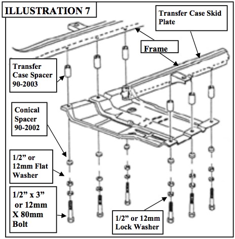
25. Support the transfer case skid plate. The transfer case and transmission are supported by the skid plate. Before removing the skid plate ensure that the transmission in properly supported. Remove the (6) bolts connecting the skid plate to the frame. Reinstall transfer case skid plate with transfer case spacers (90- 2003), conical spacers (90-2002) and supplied hardware as shown in ILLUSTRATION 7. Torque bolts to 55 ft./lbs.
NOTE: For 97-02 vehicles use the bolts from hardware pack 90-6535 and for 03-06 use pack 90-6534.
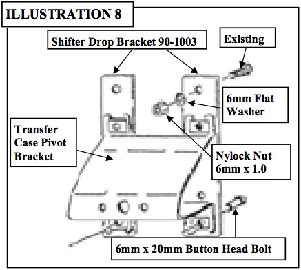
26. Install shifter drop bracket (90-1003) to pivot bracket using 6mm hardware provided. Install assembly into the existing mounting location using hardware previously removed. See ILLUSTRATION 8.
NOTE: It is very important that the shifter pivot rod protrudes through the selfaligning bearing on the pivot bracket approximately 3/8”. By bending the opposite bracket on the Transfer Case, you can easily achieve this.
27. Reconnect the front drive shaft to the axle using the reference marks as guides.
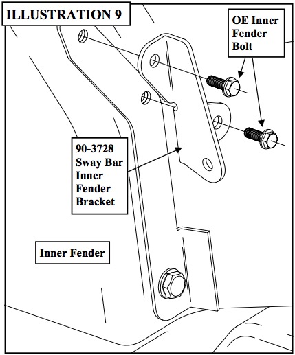
28. Remove the OE inner fender bolts shown in ILLUSTRATION 9. Save the hardware for reuse.
29. Install the sway bar inner fender bracket (90-3728) into the inner fender using the previously removed OE bolts into their original holes. See ILLUSTRATION 9.
30. Install hour glass bushings (600006) and (61150) sleeve in the top and (60859H) sleeve in the bottom of the sway bar end links (90-2638).
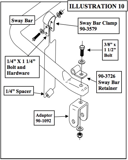
31. Install Sway Bar Clamp (90-3579) onto sway bar approximately 6” from the end of the bar with the holes facing down. Secure it to the sway bar using the 1/4”-20 X 1 1/4” bolt and hardware in the top hole (closest to the sway bar). Leave hardware loose at this time. See ILLUSTRATION 10.
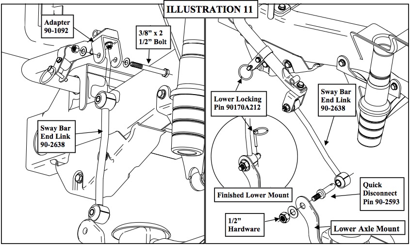
32. Install the adapter (90-1092) and sway bar retaining bracket (90-3726) onto the sway bar using the 3/8” X 1 1/2” bolt and hardware as shown in ILLUSTRATION 10.
33. Install sway bar end links (90-2638) into the adapter (90-1092) using the 3/8” X 2 1/2” bolt and hardware.
NOTE: The jog in the sway bar will face towards the outside of the vehicle. See ILLUSTRATION 11.
34. Secure the quick disconnect pin (90- 2593) to the factory lower sway bar mount location using the supplied 1/2” washer and 1/2” nylock nut.
NOTE: The pin will face toward the inside of the vehicle. See ILLUSTRATION 11.
35. Slide the lower end of the sway bar end link onto the quick disconnect pin and secure with the locking pin 90170A212 and 5/8” washer. See ILLUSTRATION 11.
36. Repeat on the remaining side of the vehicle.
37. Temporarily install the front wheels and turn lock to lock to check for interference.
When Disconnected:
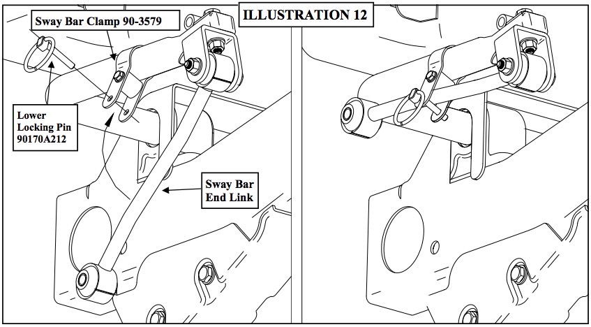
38. When disconnecting the sway bar links, swing the end links up into the previously installed clamp on the sway bar above. Secure the sway bar end link (90-2638) into the clamp (90-3579) using the previously removed locking pin 90170A212. See ILLUSTRATION 12.
39. Once the sway bar has been raised into the clamp and secured the 1/4” x 1 1/4” bolt and hardware can be tightened down. See ILLUSTRATION 12.
40. Repeat on the remaining side of the vehicle.
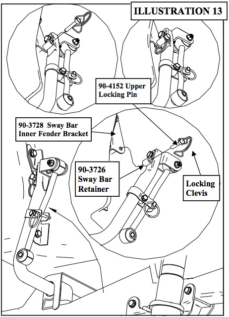
41. Secure the sway bar to the sway bar inner fender bracket (90-3728) by inserting the upper locking pin (90-4152) through the sway bar retaining bracket (90-3726) and the inner fender bracket. See ILLUSTRATION 13.
42. Lock the pin (90-4152) in place by securing the clevis over the opposite end of the locking pin. See ILLUSTRATION 13.
43. Cycle steering lock to lock and inspect steering, suspension and driveline systems for proper operation, tightness and adequate clearance. Recheck brake hose/fitting for leaks. Be sure all hoses are long enough.
44. Install the wheels and tires. Remove the jack stands and lower the vehicle.
45. Insert the sleeve (90-2603) into the rod end of the track bar (90-2627).
NOTE: The sleeve may be a tight fit and may need to be pressed in.
46.Install the track bar bushings (15-11080) and sleeve (PN 90-2249) into the track bar (PN 90-2627).
47. Install the track bar to the passenger side axle mount. Using the previously removed OE bolt. Torque this bolt to manufacturers specifications.
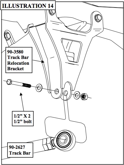
48. Bolt the rod end of the track bar to the newly installed track bar bracket (90-3580). Secure using the provided 1/2” X 2 1/2” bolt and hardware. See ILLUSTRATION 14. Torque the bolt according to the chart on page 17.
CHECKS AND ADJUSTMENTS:
Recheck all hardware for tightness after the first 100 miles.
To adjust location of front axle (side to side), place vehicle on a flat surface. With the vehicle fully on the ground and the driver side of the track bar NOT attached, center the front differential to the vehicle chassis by measuring the clearance between each tire and inner fender. This is easier done with assistance. Have your assistant sit in the drivers seat and turn the steering wheel slightly from side to side until the axle is centered. When the axle is centered, make sure your assistant holds the steering wheel in position and screw the rod end in or out until the 1/2” X 2” bolt fits through the hole and the rod end without moving the axle. Install the bolt, washers and nut. Torque the bolt according to the chart on page 17.
Steering stops can be adjusted by use of spacers behind welded jam nuts, or be use of a secondary jam nut (not provided).
Headlights should be adjusted.
By hand rotate the front and rear drive shafts with suspension hanging. Depending on engine, transmission and differential combinations, it may be necessary to increase the drop on the transfer case if u-joint-to-yoke interference is found. This can be accomplished with the use of 1/2” flat washers (not provided). 1/4” additional drop is usually sufficient.
Alignment of front wheels will be required, use factory specifications
DISASSEMBLY - REAR
1. Raise the rear of the vehicle enough for the tires to clear the ground and use jack stands on the frame to support the truck. Remove the rear tires and wheels.
2. Support the differential with your floor jack and remove the OE shock absorbers. It may be necessary to raise the differential housing slightly to facilitate their removal.
3. Locate and remove existing rear lower control arms.
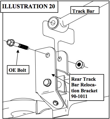
4. Disconnect lower track bar mount as shown in ILLUSTRATION 20.
5. Locate and remove rear sway bar end links and move them from the vehicle.
6. Lower the rear axle enough to remove the coil springs from the spring pockets. Save the factory isolators for re-use.
NOTE: Be sure to support the axle while the springs and shocks are removed.
7. Remove the OE bump stops from the bump stop mounting cup.
INSTALLATION - REAR
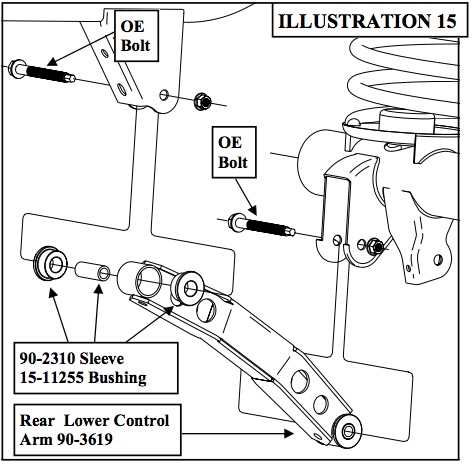
1. Assemble the rear lower control arms (90- 3619) using the (90-2310) sleeve and (15- 11255) bushings and install into the existing front and rear mounting brackets and install using hardware previously removed. Do not tighten at this time. See ILLUSTRATION 15.
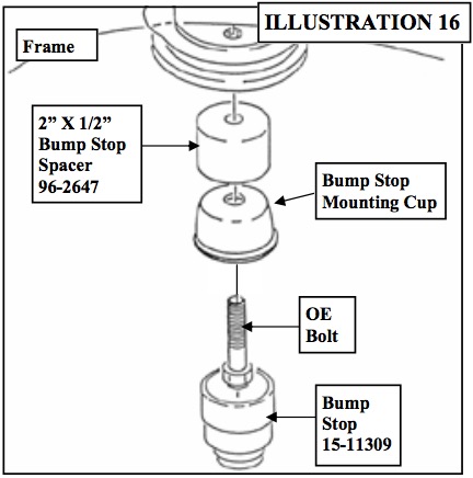
2. Bolt the bump stop cup to the frame using the previously removed OE bolt and the 1/2” X 2” bump stop spacer (96-2647). See ILLUSTRATION 16.
3. Install the supplied bump stops (15- 11309) into the OE bump stop mounting cup.
NOTE: To properly seat the newly installed bump stops, lower the weight of the vehicle onto the bump stops.
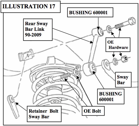
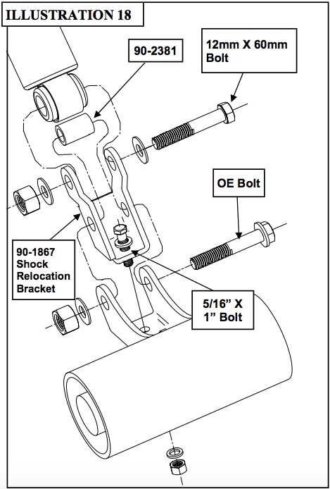
4. Assemble sway bar links 90-2009 using 60001 bushing and install as shown in ILLUSTRATION 17. When reinstalling existing stabilizer bar you must ensure that the bar is centered, equally spaced, over both side of differential housing. Fasten using existing hardware. Torque to 40 ft./lbs. 5. With the supplied 12mm X 75mm bolt and hardware from hardware pack (90-6476) install the shock relocation bracket (90-1867) to the rear axle. See ILLUSTRATION 18. 6. Install the supplied 5/16” X 1” bolt and hardware from pack (90-6476) to the bracket. The bolt head should be facing up. See ILLUSTRATION 18.
7. Install new rear coil springs (55498) and new longer shock absorbers (323509 or 923509 or MX6106). At this time, torque existing lower control arm nuts to 130 ft./lbs.
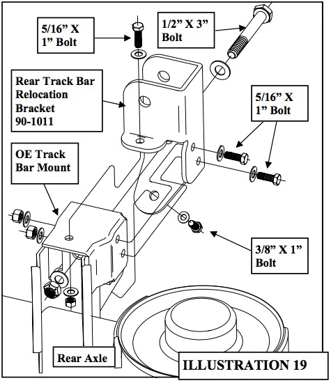
8. Referring to ILLUSTRATION 19 install rear track bar mount bracket (90-1011) using 1.60” sleeve (90-2010) the supplied 1/2” X 3” bolt, (3) 5/16” X 1” bolts, 3/8” X 1” bolt and hardware. Torque the track bar hardware according to the chart on page 17.
9. Attach track bar into new track bar mounting bracket, as shown in ILLUSTRATION 20 using hardware provided. Torque nut to 37 ft./ lbs.
10. Check the suspension and driveline systems for proper operation, tightness and adequate clearance. Recheck brake hose/fitting for leaks. Be sure all hoses are long enough.
11. Install the wheels and tires. Remove the jack stands and lower the vehicle.
12. Torque the rear lower control arm mounting bolts according to the factory manual.
CHECKS AND ADJUSTMENTS:
Recheck all hardware for tightness after the first 100 miles.
Headlights should be adjusted.
By hand rotate the front and rear drive shafts with suspension hanging. Depending on engine, transmission and differential combinations, it may be necessary to increase the drop on the transfer case if u-joint-to-yoke interference is found. This can be accomplished with the use of 1/2” flat washers (not provided). 1/4” additional drop is usually sufficient.
Notice to Owner operator, Dealer and Installer:
Vehicles that have been enhanced for off-road performance often have unique handling characteristics due to the higher center of gravity and larger tires. This vehicle may handle, react and stop differently than many passenger cars or unmodified vehicles, both on and off–road. You must drive your vehicle safely! Extreme care should always be taken to prevent vehicle rollover or loss of control, which can result in serious injury or even death. Always avoid sudden sharp turns or abrupt maneuvers and allow more time and distance for braking! Pro Comp reminds you to fasten your seat belts at all times and reduce speed! We will gladly answer any questions concerning the design, function, maintenance and correct use of our products.
Please make sure your Dealer/Installer explains and delivers all warning notices, warranty forms and instruction sheets included with Pro Comp product.
Application listings in this catalog have been carefully fit checked for each model and year denoted. However, Pro Comp reserves the right to update as necessary, without notice, and will not be held responsible for misprints, changes or variations made by vehicle manufacturers. Please call when in question regarding new model year, vehicles not listed by specific body or chassis styles or vehicles not originally distributed in the USA.
Please note that certain mechanical aspects of any suspension lift product may accelerate ordinary wear of original equipment components. Further, installation of certain Pro Comp products may void the vehicle’s factory warranty as it pertains to certain covered parts; it is the consumer’s responsibility to check with their local dealer for warranty coverage before installation of the lift.
Warranty and Return policy:
Pro Comp warranties its full line of products to be free from defects in workmanship and materials. Pro Comp’s obligation under this warranty is limited to repair or replacement, at Pro Comp’s option, of the defective product. Any and all costs of removal, installation, freight or incidental or consequential damages are expressly excluded from this warranty. Pro Comp is not responsible for damages and / or warranty of other vehicle parts related or non-related to the installation of Pro Comp product. A consumer who makes the decision to modify his vehicle with aftermarket components of any kind will assume all risk and responsibility for potential damages incurred as a result of their chosen modifications. Warranty coverage does not include consumer opinions regarding ride comfort, fitment and design. Warranty claims can be made directly with Pro Comp or at any factory authorized Pro Comp dealer.
IMPORTANT!
To validate the warranty on this purchase please be sure to mail in the warranty card.
Claims not covered under warranty -
• Parts subject to normal wear, this includes bushings, bump stops, ball joints, tie rod ends and heim joints
• Discontinued products at Pro Comp’s discretion
• Bent or dented product
• Finish after 90 days
• Leaf or coil springs used without proper bump stops
• Light bulbs
• Products with evident damage caused by abrasion or contact with other items
• Damage caused as a result of not following recommendations or requirements called out in the installation manuals
• Products used in applications other than listed in Pro Comp’s catalog
• Components or accessories used in conjunction with other manufacturer’s systems
• Tire & Wheel Warranty as per Pro Competition Tire Company policy
• Warranty claims without “Proof of Purchase”
• Pro Comp Pro Runner coil over shocks are considered a serviceable shock with a one-year warranty against leakage only. Rebuild service and replacement parts will be available and sold separately by Pro Comp. Contact Pro Comp for specific service charges.
• Pro Comp accepts no responsibility for any altered product, improper installation, lack of or improper maintenance, or improper use of our products.
E-Mail: [email protected]
Website: www.explorerprocomp.com
Fax: (619) 216-1474
Ph: (619) 216-1444

