 FREE 1 to 3-Day Delivery on Orders $149+ Details

How to Install a Pro Comp 2.5 in. Lift Kit With Shocks on your 2007-2017 Jeep Wrangler JK

Introduction:
This installation requires a professional mechanic!
We recommend that you have access to a factory service manual for your vehicle to assist in the disassembly and reassembly of your vehicle. It contains a wealth of detailed information.
Prior to installation, carefully inspect the vehicle’s steering and driveline systems paying close attention to the tie rod ends, ball joints, wheel bearing preload, pitman and idler arm. Additionally, check steering-to-frame and suspension-to-frame attaching points for stress cracks. The overall vehicle must be in excellent working condition. Repair or replace all worn or damaged parts!
Read the instructions carefully and study the illustrations before attempting installation! You may save yourself a lot of extra work.
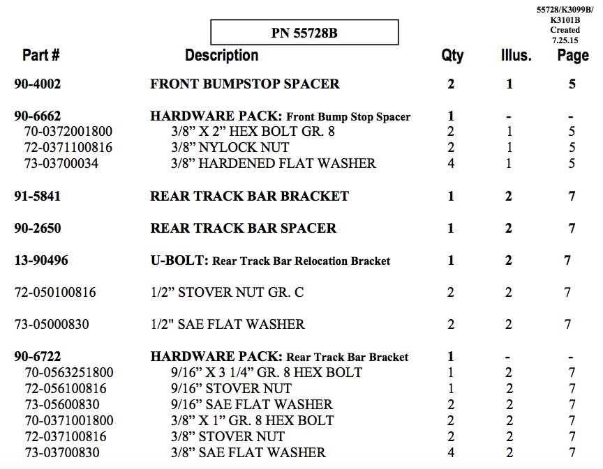
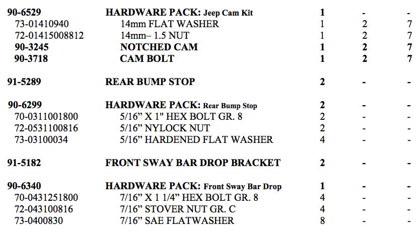
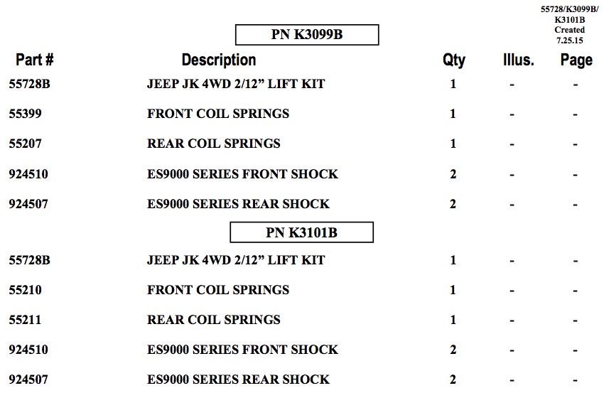
Check the parts and hardware against the parts list to assure that your kit is complete. Separating parts according to the areas where they will be used and placing the hardware with the brackets before you begin will save installation time.
Check the special equipment list and ensure the availability of these tools.
Secure and properly block vehicle prior to beginning installation.
ALWAYS wear safety glasses when using power tools or working under the vehicle!
Use caution when cutting is required under the vehicle. The factory undercoating is flammable. Take appropriate precautions. Have a fire extinguisher close at hand.
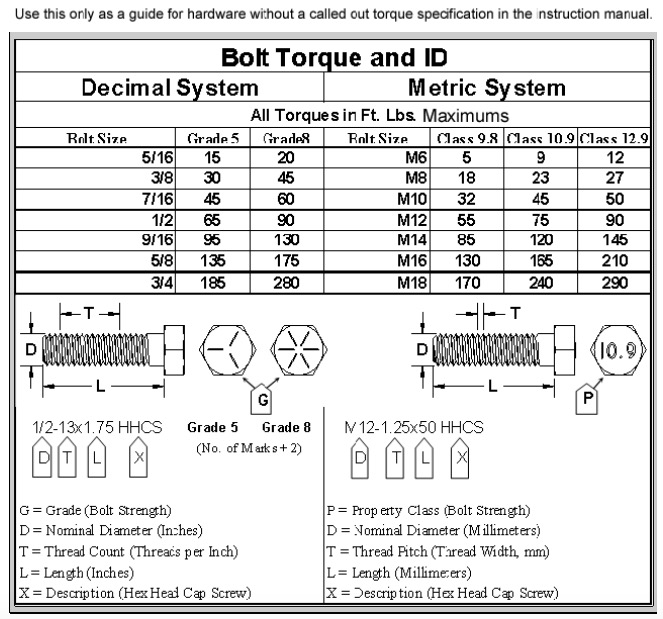
Foot pound torque readings are listed on the Torque Specifications chart at the end of the instructions. These are to be used unless specifically directed otherwise. Apply thread lock retaining compound where specified.
Please note that while every effort is made to ensure that the installation of your Pro Comp lift kit is a positive experience, variations in construction and assembly in the vehicle manufacturing process will virtually ensure that some parts may seem difficult to install. Additionally, the current trend in manufacturing of vehicles results in a frame that is highly flexible and may shift slightly on disassembly prior to installation. The use of pry bars and tapered punches for alignment is considered normal and usually does not indicate a faulty product. However, if you are uncertain about some aspect of the installation process, please feel free to call our tech support department at the number listed on the cover page. We do not recommend that you modify the Pro Comp parts in any way as this will void any warranty expressed or implied by the Pro Comp Suspension company.
PLEASE NOTE:
Due to differences in manufacturing, dimensions and inflated measurements, tire and wheel combinations should be test fit prior to installation. Tire and wheel choice is crucial in assuring proper fit, performance, and the safety of your Pro Comp equipped vehicle. For this application, we recommend a 17” wheel not to exceed 9” in width with a maximum backspacing of 5” must be used. Additionally, quality tire of radial design, not exceeding 35” tall X 12.5” wide is also recommended. Please note that the use of a 35” X 12.5” tire may require fender modification. Violation of these recommendations will not be endorsed as acceptable by Pro Comp Suspension and will void any and all warranties either written or implied.
FRONT INSTALLATION:
1. Position your vehicle on a smooth, flat, hard surface (i.e. concrete or asphalt). Block the rear tires and set the emergency brake.
2. Measure and record the distance from the center of each wheel to the top of its fender opening. Record below.

3. Place the vehicle in neutral. Place your floor jack under the front axle and raise the vehicle. Place jack stands under the frame rails and lower the frame onto the stands. Remove the jack and place the vehicle back in gear, set the emergency brake, and place blocks both in front and behind the rear wheels.
4. Unbolt and remove the transmission skid plate from the vehicle.
5. Unbolt the front sway bar frame mounts from the vehicle. Save the hardware for reuse.
6. Remove the shocks on both sides of the vehicle. It may be necessary that you slightly raise the axle to unload the shocks for removal.

7. Unbolt the front track bar from the front axle mount and secure up and out of the work area. Save the hardware for reinstallation.
8. Unbolt the all the ABS mounting clips from the vehicle.
9. Unbolt the front brake line brackets from the frame.
10. Lower the front axle enough to remove the coil springs from the front spring pockets. Save the factory isolators for re-use.
NOTE: Be sure to support the axle while the springs and shocks are removed.
11. Drill out the center of the front axle pad to 3/8”. See ILLUSTRATION 1.
12. Install the aluminum bump stop (90-4002) into the previously drilled 3/8” hole using the supplied 3/8” X 2” bolt and hardware. See ILLUSTRATION 1.
13. Carefully lower the front axle to ease in the new front coil spring installation. Using the factory isolators install the Pro Comp coil springs (55399) into the spring buckets and raise the front axle into place. Make sure the front coil spring seats properly on the lower spring perch.
14. Install the sway bar drop brackets (91-5182) using the previously removed OE hardware.
15. Reattach the sway bar frame mounts to the sway bar drop brackets (91-5182) using the supplied 7/16”” X 1 1/4” hardware.
16. Torque the sway bar hardware to 35 ft./lbs.
17. Reinstall the transmission skid plate using the previously removed OE hardware.
18. Install your new Pro Comp front shocks (MX6024 w/body end up or 924510 w/shaft end up) using the OE hardware. Torque the upper mounting hardware to 17 ft./lbs. and the lower to 35 ft./lbs.
19. Reinstall the ABS and brake line brackets to the vehicle using the previously removed OE hardware.
20. On both sides of the vehicle, check the routing of the brake lines and the ABS wire harnesses. There must be no pinching, rubbing, or stretching of either component. Use zip ties to secure these items to the steering components. At full droop, cycle the steering from lock to lock while observing the reaction of these components. Reposition them if needed.
21. Reinstall the front wheels and lower the vehicle to the ground. Torque the lug nuts according to the wheel manufacturers recommendations.
22. Reinstall the OE front track bar to the axle mount using the previously removed OE hardware. Torque the track bar mounting bolt according to manufacturers specifications
NOTES:
On completion of the installation, have the suspension and headlights realigned.
After 100 miles recheck for proper torque on all newly installed hardware.
Recheck all hardware for tightness after off road use.
REAR INSTALLATION:
1. Block the front tires and raise the rear of the vehicle. Support the frame with jack stands forward of the rear springs.
2. Remove the rear wheels.
3. Unbolt the rear track bar from the rear axle mount and secure up and out of the work area. Save the hardware for reinstallation.
4. Remove the shocks on both sides of the vehicle. It may be necessary that you slightly raise the axle to unload the shocks for removal.
5. Unbolt and remove the rear sway bar end links from the vehicle. Save the hardware for reuse.
6. Unbolt the rear brake line brackets from the vehicle.
7. Lower the rear axle enough to remove the coil springs from the rear spring pockets. Save the factory isolators for re-use.
NOTE: Be sure to support the axle while the springs and shocks are removed.
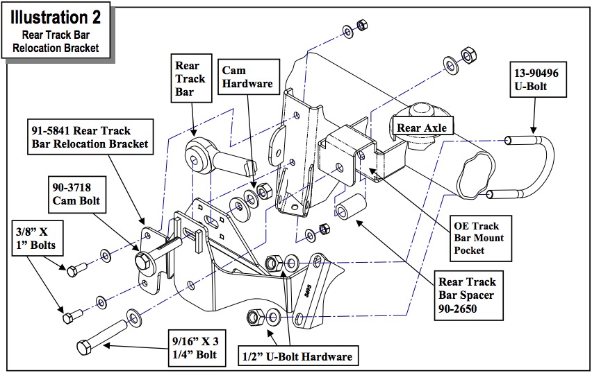
8. Install the driver side rear track bar relocation bracket (91-5841) into the original track bar mounting pocket using the supplied 9/16” X 3 1/4” bolt and supplied spacer (90-2650). See ILLUSTRATION 2.
9. Insert the (2) 3/8” X 1” bolt into the track bar bracket and secure it to the driver side rear axle shock mount. See ILLUSTRATION 2.
10. Tighten the previously installed 9/16” and 3/8” hardware.
11. Install the U-bolt around the rear end axle tube and secure to the rear track bar relocation bracket (91-5841) using the supplied 1/2” washer and nut. See ILLUSTRATION 2.
12. Torque the 3/8”, 1/2” U-bolt and 9/16” track bar hardware according to the torque chart on page 9.
13. Install the rear bump stop (91-5289) onto the axle pad. Secure through the existing holes in the axle pad using the (2) supplied 5/16” X 1” bolts and hardware. Torque bolts according to the torque chart on page 9.
14. Carefully lower the rear axle to ease in the new rear coil spring installation. Using the factory isolators install the Pro Comp rear coil springs (55207) into the spring buckets and raise the rear axle into place. Make sure the coil spring seats properly on the lower spring perch
NOTE: Be sure to reinstall the factory isolators before raising the springs into place.
15. Install your new Pro Comp rear shocks (MX6155 w/body end up or 924507 w/shaft end up) using the OE hardware. Torque the upper mounting hardware to 20 ft./lbs. and the lower to 35 ft./lbs.
16. Reinstall the sway bar end links using the previously removed OE hardware.
17. Reinstall the rear brake line brackets to the vehicle using the previously removed OE hardware.
18. On both sides of the vehicle, check the routing of the brake lines and the ABS wire harnesses. There must be no pinching, rubbing, or stretching of either component. Ensure lines are also clear of any moving parts. Reposition lines if needed.
19. Reinstall the rear wheels and lower the vehicle to the ground. Torque the lug nuts according to the wheel manufacturers recommendations.
20. Install the rear track bar to the relocation bracket (91-5841) using the supplied adjustable cam bolt (90-3718) and hardware from hardware pack (90-6529). Do not torque the cam bolt at this time. See ILLUSTRATION 2.
21. Position your vehicle on a smooth, flat, hard surface (i.e. concrete or asphalt).
22. Rotate the track bar cam bolt until the wheels are centered under the vehicle.
23. Torque track bar cam bolt to 103 ft./lbs.
24. Drive the vehicle forward and backward a few feet to be sure that the axle is adjusted properly and the vehicle is tracking in a straight line.
IMPORTANT!: If the steering wheel is not centered properly it will trigger the anti-lock brake and traction control warning lights.
NOTES:
On completion of the installation, have the suspension and headlights realigned.
After 100 miles recheck for proper torque on all newly installed hardware.
Recheck all hardware for tightness after off road use.
Modifications Page:
8.30.12: Moved (90-3718) cam bolt into hardware pack (90-6529).
10.1.12: Changed kit fitment to include 2013.
4.10.14: Updated rear install step 18.
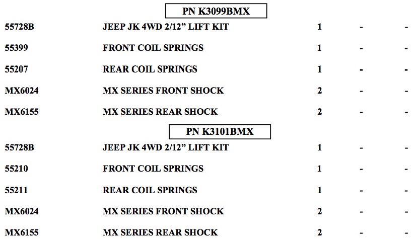
7.25.15: Added K3101B, K3101BMX, K3099B, K3099BMX to the BOM.

The PRO COMP PROMISE WARRANTY
At Pro Comp, we know you have many choices when selecting products to personalize your vehicle. You should demand nothing but the highest quality available and have total confidence that the products you selected are the best in the industry. It is for these reasons that Pro Comp Suspension products are backed by the best warranty in the industry...the Pro Comp Promise!
Pro Comp promises that its products will last a lifetime or we will replace it free of charge. It’s that simple! Because of our commitment to quality and manufacturing excellence, we are able to stand behind our products. FOREVER. It is Pro Comp’s Promise that if one of our suspension products breaks not due to misuse, neglect or vandalism, we will replace it. Whether you are the original purchaser or not, you can be assured that we will make it right. The Pro Comp Promise covers all suspension products including shocks and steering stabilizers. Buy Pro Comp Suspension today and enjoy it for the rest of your life!
That’s our Pro Comp Promise!
Notice to Owner, Operator, Dealer and Installer:
Vehicles that have been enhanced for off-road performance often have unique handling characteristics due to the higher center of gravity and larger tires. This vehicle may handle, react and stop differently than many passenger cars or unmodified vehicles, both on and off–road. You must drive your vehicle safely! Extreme care should always be taken to prevent vehicle rollover or loss of control, which can result in serious injury or even death. Always avoid sudden sharp turns or abrupt maneuvers and allow more time and distance for braking! Pro Comp reminds you to fasten your seat belts at all times and reduce speed! We will gladly answer any questions concerning the design, function, maintenance and correct use of our products.
Please make sure that the Dealer / Installer explains and delivers all warning notices, warranty forms and instruction sheets included with Pro Comp product.
Warranty and Return Policy:
Pro Comp warranties its full line of products to be free from defects in workmanship and materials for the life of the product. Pro Comp’s obligation under this warranty is limited to repair or replacement, at Pro Comp’s option, of the defective product. Any and all costs of removal, installation, freight or incidental or consequential damages are expressly excluded from this warranty. Pro Comp is not responsible for damages and / or warranty of other vehicle parts related or non-related to the installation of Pro Comp product. A consumer who makes the decision to modify his vehicle with aftermarket components of any kind will assume all risk and responsibility for potential damages incurred as a result of their chosen modifications. Warranty coverage does not include consumer opinions regarding ride comfort, fitment and design. Warranty claims can be made directly with Pro Comp or at any factory authorized Pro Comp dealer.
IMPORTANT! To validate the warranty on this purchase please be sure to mail in the warranty card. Claims not covered under warranty
* Parts subject to normal wear; this includes bushings, bump stops, ball joints, tie rod ends and heim joints.
* Finish after 90 days.
* Damage caused as a result of not following recommendations or requirements called out in the installation manuals.
Pro Comp MX Series coil-over shocks are considered a serviceable shock with a one-year warranty against leakage only. Rebuild service and replacement parts will be available and sold separately by Pro Comp. Contact Pro Comp for specific service charges. Pro Comp accepts no responsibility for any altered product, improper installation, lack of or improper maintenance or improper use of our products.
E-Mail: [email protected]
Website: www.procompusa.com
Fax: (310) 747-3912
Ph: 1-800-776-0767
