FREE 1 to 3-Day Delivery on Orders $149+ Details

How to Install Poison Spyder RockerBrawler Rear Bumper w/ Tire Carrier - Bare Steel on your Wrangler
Tools Required
- Primer, paint, cleaners and masking materials (if painting)
- Mechanic’s tool set with a full assortment of SAE and metric end wrenches, sockets, ratchets, hex keys, etc.
- 18mm socket
- 9/16” socket
- Ratchet
- Torque wrench
- T27 Torx driver bit with ratchet
- 1-1/2” socket with breaker bar
- 2-12” wrench, socket or big-ass crescent wrench
- Pop rivet install tool
- Bearing seal driver or soft dead-blow hammer
- Shop press or heavy hammer
- Loctite® 242 (blue) or equivalent thread lock compound
- Anti-sieze thread lubricant
- Quality wheel bearing grease
- Wheel bearing grease packing tool OR the skill to pack bearings by hand
- Latex or nitrile gloves
- Felt-tip fine point marker

Shop Parts in this Guide
APPLICATIONS
These installation instructions apply to the following Poison Spyder products:
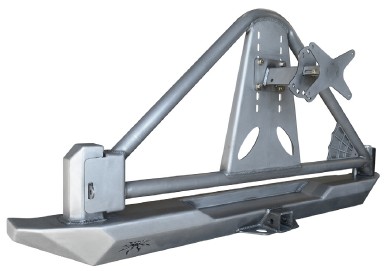
14-61-020 TJ RockBrawler Rear Bumper with Tire Carrier (shown above)
14-61-020-D TJ RockBrawler Rear Bumper with Tire Carrier & Recovery Shackle Tabs
PARTS LIST
(1) TJ RockBrawler Rear Bumper with Tire Carrier Spindle & Latch
Housing
(1) TJ RockBrawler Rear Bumper Mount Hardware Kit
PN: HWKIT-14-61-010 includes:
(8) 3/8-16 Gr8 Nylon Insert Lock Nut
(8) 3/8” SAE Hardened Flat Washer
(1) RockBrawler Tire Carrier
Pre-assembled with:
(2) Tapered Roller Bearing 1.375 ID 0.7200 Width
(1) 1”-14 Gr8 Nylon Insert Lock Nut
(1) 1” SAE Hardened Flat Washer
(1) Spyder Web Gusset Detail
(1) RockBrawler Tire Carrier Hardware Kit
PN: HWKIT-17-61-020 includes:
(1) Stainless Steel Lock Pin Scuff Plate
(2) 3/16” Dia. X .126-.250” Aluminum Pop Rivet
(1) Billet Knob
(1) Billet Aluminum Threaded Cap
(1) #145 Nitrile O-Ring 2-9/16 ID X 2-3/4 OD
(1) Radial Shaft Seal CR19226/Timken 50455
(3) 10-24 X 3/4 SS Button Head Socket Cap Screw
(3) #10 SS Flat Washer
(3) 10-24 SS Nylon Insert Lock Nut
(1) 1/4-20 Bent-Swivel Ball Joint Linkage
(1) Black Phenolic Knob with 1/4-20 Shank Extension
(1) 1/4” SAE Hardened Flat Washer
(1) 1/4-20 Gr8 Nylon Insert Lock Nut
(1) 1/4-20 X 4-1/2 Threaded Stud
(1) Rock Brawler Pivot Cap Wrench
(1) 3-Piece Adjustable Tire & License Plate Mount Kit
Includes:
(1) Adjustable Tire Mount - Carrier Side
(1) Adjustable Tire Mount - Tire Side
(1) Adjustable License Plate Mount
(1) 3-Piece Adjustable Tire & License Plate Mount Hardware Kit
PN: HWKIT-17-61-030 includes:
(4) 7/16-14 X 1 Gr8 Hex Head Cap Screw
(4) 7/16-14 Gr8 Nylon Insert Lock Nut
(8) 7/16” SAE Hardened Flat Washer
(3) 3/8-16 X 1 Gr8 Hex Head Cap Screw
(6) 3/8” SAE Hardened Flat Washer
(3) 3/8-16 Gr8 Nylon Insert Lock Nut
(4) 1/4” SS Flat Washer
(4) 1/4-20 X 3/4 SS Button Head Socket Cap Screw
(6) 1/4-20 Gr8 Nylon Insert Lock Nut
(4) 1/4” SAE Hardened Flat Washer
(2) 1/4-20 X 3/4 Gr8 Hex Head Cap Screw
(3) 1/2-20 X 1.72/1.750 Length Wheel Lug Bolt
(3) 1/2-20 X 15/16 Hex 60° Seat Open Lug Nut
INSTALLATION PROCEDURE
1. Park the Jeep on a flat, level surface and set the parking brake.
2. Remove existing rear bumper. If it is the stock bumper, use a T27 Torx driver to remove the plastic bumper extensions, then use an 18mm socket and ratchet remove the large nuts/bolts from the frame rail side brackets and along the bottom of the bumper. Keep the OE hardware as some of it will be re-used.
3. Remove the pre-installed 3/8-16 nylon insert lock nuts and washers from the Bolt Plates on the inside of the RockBrawler bumper. Do not remove the Keeper Washers that hold the Bolt Plates in place. Note that there are several sets of unused bolt slots on the bumper’s internal mounting surface. These are for different Jeep models, please disregard them for your application.
4. Install the RockBrawler bumper. The bolts in the captured bolt plates will align with the mounting holes in the Jeep’s frame/bumper brackets. The Bolt plates are captured in horizontal slots to allow for some adjustment and manufacturing variances in the Jeep’s frame. Install the provided 3/8-16 nylon insert lock nuts and 3/8 flat washers on to the threaded studs of the Bolt Plates, where they protrude through the Jeep’s mounting bracket. Do not fully tighten them at this time.
5. Use two (2) of the 10mm OE mounting bolts (18mm wrench size) to bolt through the slots located along the underside of the bumper into the OE welded-in-place nuts inside the rear crossmember. Do not fully tighten them at this time.
6. With all hardware installed, check that the bumper is level and correctly aligned with the Jeep, as the slots in the Bolt Plates will allow for a small amount of adjustment. It may be easiest to slightly tighten each of the bolts then use a soft dead blow hammer or rubber mallet to lightly tap the bumper to make fine adjustments.
7. Once the bumper is correctly levelled and aligned, tighten all mounting bolts to 45 ft./lbs.
NOTE: The photos shown in the following steps depict the tire carrier installation on a JK version of the RockBrawler Rear Bumper, however the procedure is the same for the TJ/YJ/CJ version.
8. Use the two (2) supplied 3/16” pop rivets to attach the crescent-shaped stainless steel Lock Pin Slider Plate to the bumper at the base of the hinge spindle.
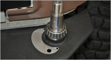
9. Wearing latex or nitrile gloves, “Pack” the two tapered roller bearings with a quality wheel bearing grease by hand or with a bearing packing tool. The two matching bearing races are already pressed in to the tire carrier hinge housing.
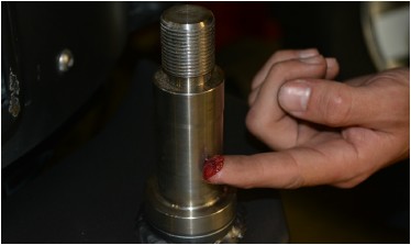
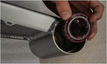
10. Apply a light sheen of grease to the bare metal surfaces of the inside of the tire carrier pivot housing and bearing races, as well as the hinge spindle on the bumper (do not coat the threads for the spindle nut). This will help discourage rust formation on these bare metal surfaces.
NOTE: Photos used in the following steps depict a different model Poison Spyder bumper and tire carrier. However the tire carrier pivot spindle and bearing assembly, and the assembly procedures, are identical for this bumper model.
11. Insert a Tapered Roller Bearing into the pre-installed Lower Race, inside the Hinge Housing. Ensure that it seats correctly and “feels right” in the race. Excess grease may hold it in place temporarily, but it may be helpful to turn the tire carrier upside down until the next step is completed.
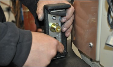
12. Use a bearing seal driver tool to carefully install the grease seal into the bottom of the hinge housing. If the proper tool is not available, the step may be performed by carefully using a large socket of the approximate diameter of the seal and a soft dead-blow hammer to work the seal into its seat. Be very careful to drive the seal in evenly, do not let it get misaligned while driving it in.
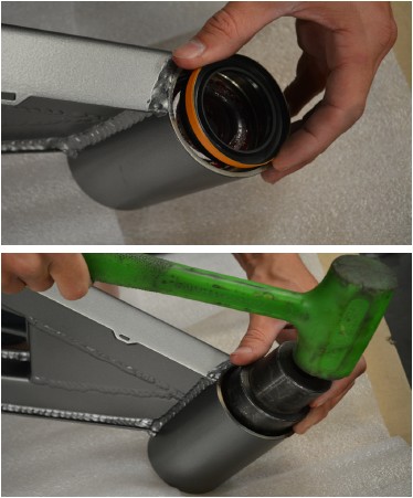
13. Install the Tire Carrier onto the bumper, carefully guiding the hinge housing down over the hinge spindle. Be careful not to damage the grease seal when lowering the tire carrier on to the spindle. There is a very tight-tolerance slip-fit between inner diameter of the tapered roller bearing and its seating surface on the spindle. Be careful not to let the bearing get misaligned as you lower the carrier onto the bumper. Have a friend support the opposite end of the tire carrier during this and the next two steps.
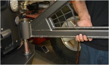
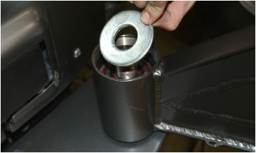
14. Install the remaining Tapered Roller Bearing by dropping it down over the hinge spindle, narrow end pointed downward. Carefully slide it down the spindle until it is seated into the upper race.
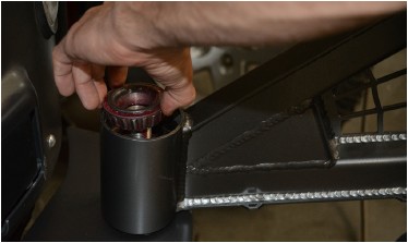
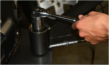
15. Apply some anti-sieze thread lubricant to the threads on the spindle. Install the large 1” Flat Washer next on the spindle, followed by the 1”-14 Lock Nut. Tighten the lock nut until it just touches the washer and bearing, then have your friend slowly swing the tire carrier back and forth as you tighten the lock nut the rest of the way.
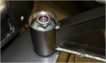
We can not supply a torque specification for this nut, just get it as tight as it takes to properly seat the bearings and provide smooth operation of the tire swing without any “play”. Re-tighten this nut after the weight of the spare tire and accessories have been added, and again after a few days or a hundred miles of use. You may need to re-tighten this nut several more times until it permanently seats.
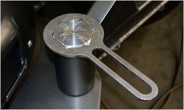
16. Install the Pivot Cap O-Ring onto the outside of the threads of the Billet Hinge Cap, just under the head of the cap (NOTE: this may have already been done prior to shipment).
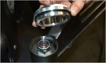
17. Thread the Hinge Cap onto the Hinge Housing and lightly tighten with the provided Pivot Cap Wrench. Note that you may have to remove it in later steps to further tighten the spindle lock nut, so don’t fully tighten the cap until installation is complete.
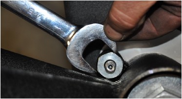
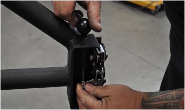
18. Install the Lock Pin Assembly into the provided housing (on the side of the hinge bearing housing). Use an open-end wrench to carefully tighten the hex head of the pin assembly.
19. Install the billet Lock Pin Knob onto the threads of the Lock Pin Assembly. Use a drop of blue Loctite or thread locker on the threads.
20. Install the Latch Receiver into the latch receiver housing on the bumper as shown in Figure 11 using (2) 5/16-18 X 3/4 SS Button Head Cap Screws with a drop of Loctite® 242 (blue) or equivalent thread lock compound on the threads of each fastener. The rubber bumpers at the top and bottom of the receiver should taper (get narrower) toward the rear of the latch receiver housing (toward the front of the Jeep). Leave the two screws untightened until completing the next step.
21. Install the Latch Pin into the Latch Receiver, as shown in Figure 11, with a drop of Loctite® 242 (blue) or equivalent thread lock compound on the threads of the latch pin. Tighten with a Torx T50 driver bit, then tighten the two button head cap screws that were installed in the previous step.
22. Install the Latch mechanism into the latch mechanism housing on the tire carrier as shown in Figure 12, using the (3) 5/16-18 X 1-1/2 SS Button Head Cap Screws and (3) 5/16-18 Nylon Insert Lock Nuts. The through-holes in the latch mechanism will correspond to the holes in the latch mechanism housing, making its intended orientation obvious. Make sure the button heads are to the outside, and the lock nuts are on the inside. Snug these fasteners at this time, but do not fully tighten them until the final steps.
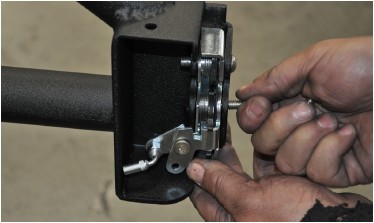
23. Install the Ball Joint Elbow onto the Latch Mechanism actuator arm as shown in Figure 2, with a 1/4-20 Nylon Insert Lock Nut on the back side of the threaded stud of the elbow.
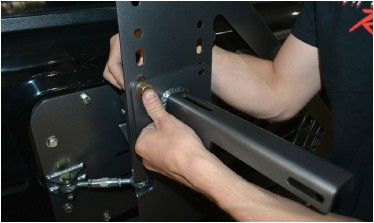
24. Insert the Threaded Latch Rod through the small hole in the top of the latch mechanism housing and thread it into the threaded elbow with a drop of Loctite® 242 (blue) or equivalent thread lock compound on the threads.
25. Thread the Latch Knob onto the end of the Threaded Latch Rod with a drop of Loctite® 242 (blue) or equivalent thread lock compound on the threads.
NOTE: If testing the alignment of the latch components at this time, they may be significantly vertically misaligned. We intentionally build the Tire Carrier with “pre-load” so that once the weight of the spare tire is on it, it will more closely align. Do not worry about misalignment until after the spare tire is mounted in the later steps.
26. Use three #10-32 X 3/4 SS button head cap screws with #10-32 nylon insert lock nuts to attach the Spyder Web Gusset Detail to the gusset on the tire carrier. Use a drop of Loctite® 242 (blue) or equivalent thread lock compound on the threads of each fastener.
27. Measure the overall height of your spare tire (NOT one of the mounted tires on your Jeep!), divide that measurement in half, then add one inch. The resulting number will be your tire mount height measurement. With the Tire Carrier closed and latched, measure upward from the recessed step surface of the bumper, and make a small mark on the tire carrier at the tire mount height measurement.
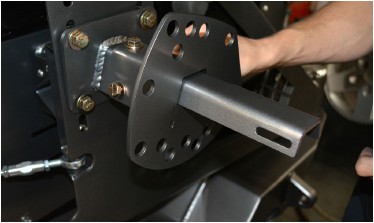
28. Use (4) 7/16-14 x 1 Gr8 Hex Head Cap Screws with (4) 7/16 Flat Washers and (4) 7/16-14 Nylon Insert Lock Nuts to attach the Tire Mount - Carrier Side to the Tire Carrier, centered on the mark you made in the previous step. The slots in the tire carrier allow for some adjustment, however if there isn’t enough adjustment to center the Tire Mount exactly centered on your mark, move it up slightly to the next set of slotted holes in the carrier. Tighten the four bolts/nuts to approximately 50 ft.-lbs.
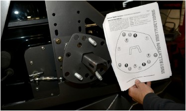
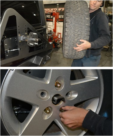
29. Look at the Tire Mount - Tire Side, and note that there are wheel stud holes for several different bolt patterns. Use the Bolt Pattern Template provided at the end of these instructions to determine which THREE holes to use for your specific bolt pattern. Once the three holes are correctly identified, mark them with a felt-tip marker.
30. Use a shop press or hammer to drive the three provided Wheel Studs into the mounting plate, using the holes that were marked in the previous step. Make sure the studs point in the opposite direction from the V-channel piece that is welded to the back of the plate.
31. Lay your spare tire on the floor with the mounting surface of the wheel pointed up. Lay a long straight edge (yardstick, level, or other suitable item) across the middle of the tire. Measure the vertical distance from the straight edge to the wheel mounting surface. This is the Overall Offset measurement, including any bulge in the tire sidewall.
NOTE: Photos used in the following steps depict a different model Poison Spyder bumper and tire carrier. However the 3-piece Adjustable Spare Tire and License Plate Mount, and the assembly procedures, are identical for this bumper model.
32. Use (4) 7/16-14 x 1 Gr8 Hex Head Cap Screws with (4) 7/16 Flat Washers and (4) 7/16-14 Nylon Insert Lock Nuts to attach the Tire Mount - Carrier Side to the Tire Carrier, centered on the mark you made in the previous step. The slots in the tire carrier allow for some adjustment, however if there isn’t enough adjustment to center the Tire Mount exactly centered on your mark, move it up slightly to the next set of slotted holes in the carrier. Tighten the four bolts/nuts to approximately 50 ft.-lbs.
33. Look at the Tire Mount - Tire Side, and note that there are wheel stud holes for several different bolt patterns. Use the Bolt Pattern Template provided at the end of these instructions to determine which THREE holes to use for your specific bolt pattern. Once the three holes are correctly identified, mark them with a felt-tip marker.
34. Use a shop press or hammer to drive the three provided Wheel Studs into the mounting plate, using the holes that were marked in the previous step. Make sure the studs point in the opposite direction from the V-channel piece that is welded to the back of the plate.
35. Lay your spare tire on the floor with the mounting surface of the wheel pointed up. Lay a long straight edge (yardstick, level, or other suitable item) across the middle of the tire. Measure the vertical distance from the straight edge to the wheel mounting surface. This is the Overall Offset measurement, including any bulge in the tire sidewall.
36. Fit the Tire Mount - Tire Side channel on to the corresponding beam of the Tire Mount - Carrier Side. Use (3) 7/16-14 X 3 Gr8 Hex Head Cap Screws with (6) 7/16 Flat Washers and (3) 7/16-14 Nylon Insert Lock Nuts to secure the Tire Mount-Tire Side to the Tire Mount - Carrier Side, using the slotted holes provided. Adjust the position of the mounting surface of the distance between the Tire Mount and the surface of the tire carrier frame is 1/4 to 1/2 inch LESS THAN the Overall Offset measurement found in the previous step. Once properly adjusted, tighten the three bolts/nuts to approximately 50 ft.-lbs.
NOTE: Some tire/wheel combinations, such as 12.50 wide tires on stock Jeep wheels, may require more Overall Offset than the adjustment in the Tire Mount components allows (approximately 4-3/4” to 6-3/4”). In these cases, source a wheel spacer of suitable thickness to make up the difference.
37. Lift the spare tire onto the Tire Mount - Tire Side, and fit the previously installed lug studs through the holes in the wheel. Tighten the (3) Lug Nuts. This will draw the sides of the tire tightly against the frame of the Tire Carrier, to prevent rattles and squeaks.
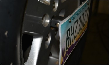
38. Use (4) 1/4-20 X 3/4 SS Button Head Cap Screws, (4) 1/4 Flat Washers and (4) 1/4-20 Nylon Insert Lock Nuts to fasten your license plate to the License Plate Mount.
39. Use the 1/4-20 X 3/4 Hex Head Cap Screws with 1/4 Flat Washer and 1/4-20 Wing Nut to fasten the License Plate Mount to the Tire Mount at the center of the spare tire.
Note that you will need to keep these wrenches available in the vehicle in order to remove the license plate mount to access your spare tire in the future.
40. Once the entire bumper is mounted and tested for proper operation, remove and disassemble the bumper for paint or powder coat. If painting yourself, careful preparation will make a big difference in the quality and longevity of your paint job, even using “rattle can” aerosol paints. Begin by thoroughly cleaning the bumper with solvent or de-greaser, then make sure all residue is removed. Even if you use cheap paint, try to use a good quality primer. “Etching” primers are best to use on bare, unpainted metal. Allow it to properly dry before painting, and between paint coats. Note that the Spyder Web Gusset Detail is detachable so that it may be painted or powder coated a contrasting color from the rest of the bumper.
If powder coating, make sure the entire bumper and tire carrier are completely disassembled first. Make sure the bearings, races and grease seal are not yet installed. Make sure your powder-coater understands that the hinge spindle must be masked off (not coated).
41. Once the bumper has been painted or powder coated, re-install by repeating the above steps.
Congratulations, you have completed installation of your RockBrawler Rear Bumper and Tire Carrier!
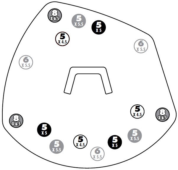
BOLT PATTERN TEMPLATE
Use this Bolt Pattern Template to determine the correct holes to use in the Tire Mount - Tire Side plate, for your specific bolt pattern. The plate can be used for any of 5 different bolt patterns, each of which uses 3 holes which can be identified using the template. The list at right identifies some of the vehicle models each bolt pattern is typically used with, although there may be exceptions.
5 X 4.5 ‘87-’96 Jeep YJ, ‘97-’06 Jeep TJ, ‘84-’01 XJ
5 X 5.5 Jeep CJ, 1/2-ton Ford & Dodge trucks*
5 X 5 2007 Jeep JK
6 X 5.5 Toyota, 1/2-ton Chevy & Jeep trucks*
8 X 6.5 Ford, GM, Dodge & Jeep 3/4- & 1-ton trucks*
*Prior to converting to metric for various models