 FREE 1 to 3-Day Delivery on Orders $149+ Details

How to Install Poison Spyder Lazer-Fit Full Cage Kit on your Wrangler
Tools Required
- Mechanic’s tool set including Torx bit set
- T-50 “Tamper-Proof” Torx bit
- Ratchet straps
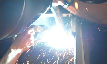
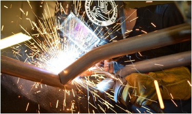
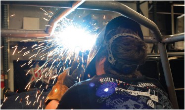
- Welder and proper welding equipment
- Drill motor with assortment of drill bits
- Tap handle and assorted threading taps

Shop Parts in this Guide
APPLICATIONS
These installation instructions apply to the following Poison Spyder products:
INSTALLATION NOTES
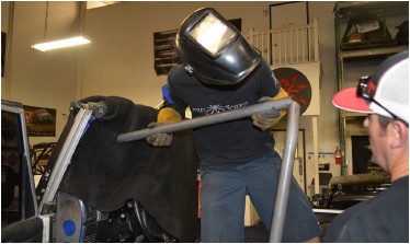
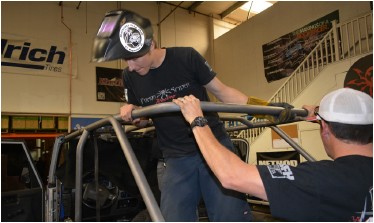
Installation of the Full Cage Kit can take up to 8 hours. This kit requires welding, which should be done by a certified welder. You will need a friend or two to assist with the installation. A good set of Torx bits is required for removal of the factory cage, including a T-50 “tamper-proof” Torx bit.
IMPORTANT: It is imperative that the top, doors, seats, plus any other components that are going to be reinstalled after the cage install be test-fitted BEFORE final welding of the cage! Poison Spyder Customs is not liable for fitment issues due to negligent install.
REMOVAL OF THE FACTORY CAGE
1. Park vehicle on a level surface and set the emergency brake. You will want to wear eye protection beyond this point.
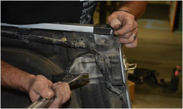
2. Remove the front factory spreader bars from the cage main hoop and the windshield. Save the four bolts that were used to fasten the bars to the windshield (two on each side), they will be re-used later.
3. Remove the factory roll bar from the vehicle. Be careful to not strip the Torx bolts, as they will be re-used. It may be necessary to bend the sheet metal body bracket that attaches to the roll bar from the inside of the body tub, just behind the front seat on each side. Remove the seatbelts from the roll bar.
4. On Jeeps with factory soft tops, remove the soft top brackets located on the factory roll bar. These can be re-attached to the new roll bar.
5. Along the front of the door jamb, there are three Torx bolts positioned in a vertical line, going into the firewall. Remove all three bolts from both sides.
INSTALL PROCEDURE
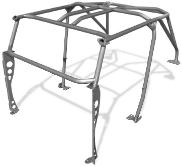
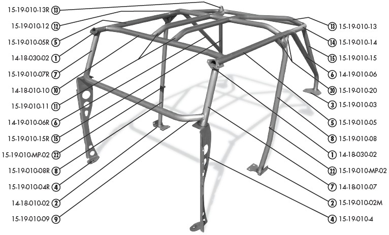
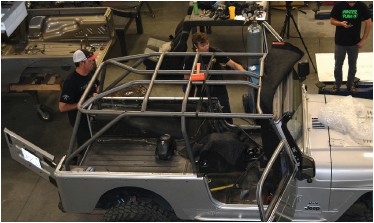
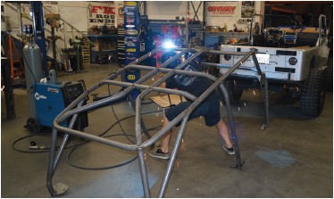
NOTE: Refer to the assembled cage diagram at the top of Page 3 for general reference and placement of the cage components. Carefully inspect each part and its placement prior to tacking and finish-welding.
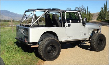
NOTE: The photos used in these instructions are from an installation in an Unlimited (LJ). The procedure is nearly identical, but the text of these procedures have been edited specifically for the TJ.
6. Place protective welding blankets over all interior components, carpets, dash, steering wheel, etc. Tape blankets over the windshield glass to protect it from pitting from weld splatter.
7. Clean ALL bare metal pieces provided in the kit, using a clean rag and brake cleaner. This will ensure an easier, cleaner installation and better welds later in the installation.
8. Use the OE hardware to Install the Windshield Mount Plates 1 on either side of the windshield, using the factory hardware that held the OE spreader bars in place. Make sure the half-moon cut-outs are oriented with the flat side down, parallel with the ground as shown.
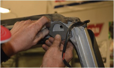
9. Use the OE roll bar hardware to Install the B-Pillar Mount Plate 2 in the locations where the main hoop of the factory roll bar bolted in, just behind the door opening on either side.
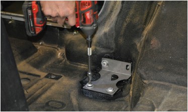
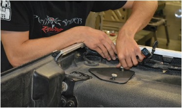
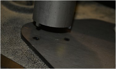
10. Install the C-Pillar Mount Plates 3 where the factory roll bar bolted in at the rear corners. Orient the plates with the rounded point edge facing the rear of the Jeep. Secure them using the OE hardware, leave the bolts slightly loose.
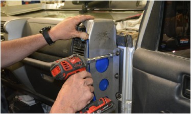
11. Install the Lower A-Pillars L&R 4 . Bolt each Lower A-Pillar into place using the three Torx bolts you removed during Step 5 of the Factory Cage Removal process. Note that once installed, the Lower A-Pillars will NOT be oriented perpendicular to the Jeep. They will angle slightly inward. Be sure to test-fit the doors for proper closing, before proceeding.
12. Use a large crescent wrench to bend the sheet metal roll bar brackets back into place, as they were likely bent backward during the removal of the stock roll bar.
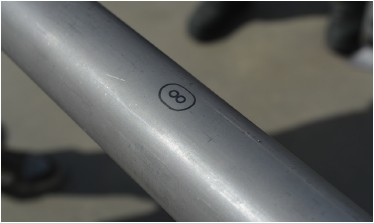
13. Place the driver’s side B-Pillar 8 on to the B-Pillar Mount plate. The end with the straight, stepped edge is the bottom end, make sure it engages correctly with the half-moon cut-out in the mount plate.
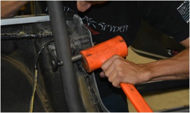
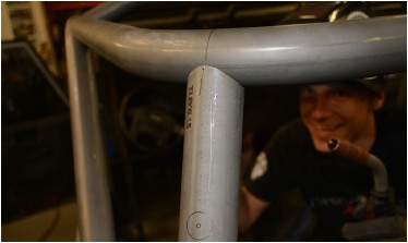
14. Insert a B-Pillar Bolt Sleeve 22 into the B-Pillar, through the hole provided that aligns with the sheet metal roll bar bracket that is attached to the tub. It may be necessary to sand or de-bur the ends of the sleeve and/ or the edges of the laser cut holes in the B-Pillar. Use a soft dead-blow mallet to tap the sleeve in to place, leaving approximately 1/2” of the tube protruding out the rear side of the B-Pillar, against the sheet metal roll bar bracket.
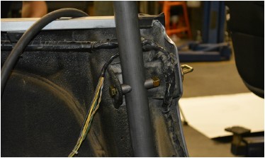
15. Insert a 1/2-13 X 3-3/4 Gr8 Hex Head Cap Screw through a 1/2” Flat Washer, through the hole in the sheet metal roll bar bracket, through another 1/2” Flat Washer, then through the B-Pillar Bolt Sleeve. Install a 1/2-13 Gr8 Nylon Insert Lock Nut on to the bolt where it protrudes through the sleeve, leaving it only finger-tight for now.
16. Install the driver’s side Header Bar 5 .
The straight/step-cut end of this piece should be oriented toward the front, with the end of the tube fitting into the half-moon cut of the Windshield Mount Plate that was installed in an earlier step.
The other end of the Header Bar has laser-cut slots that are designed to click into place on the tabs protruding from the end of the B-Pillar. Just set the Header Bar in place for now, do not tack or weld yet.
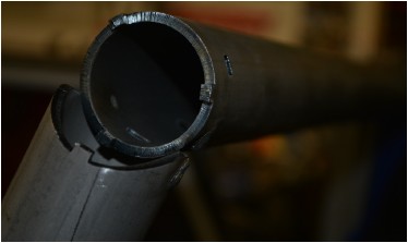
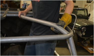
17. Install the driver’s side Rear Down Bar 6 Begin by inserting a Header Bar Sleeve 21 into the flat-cut end of the Rear Down Bar. It may be helpful to file, sand or de-bur the laser-cut edges of the Header Bar Sleeve before inserting. The Header Bar Sleeve should be inserted approximately half-way into the Rear Down Bar. There is a small round hole laser cut a couple inches from the end of the Rear Down Bar tube, where a rosette weld will be made in later steps to hold the Header Bar Sleeve in place. Make sure the sleeve is inserted past the rosette hole.
Insert the other end of the Header Bar Sleeve into the Header Bar that was set into place in a previous step.
Take care to make sure the sleeve inserts into the Header Bar so that its edge is past the rosette hole in the bottom of the Header Bar, while the other end is still past the rosette hole in the Rear Down Bar. Slide the Header Bar and the Rear Down Bar together until they meet (the will be slightly separated by tabs cut into the ends of the tubes).
At the other end of the Rear Down Bar, insert the tabs that were laser cut into the end of the tube, into the corresponding slots cut into the C-Pillar Mount Plate that was installed in a previous step. It may be necessary to slightly adjust the position of the plate.
At the forward end of the Rear Down Bar, make sure that both it and the Header Bar seat properly into the notched end of the B-Pillar. There are tabs and slots cut into each piece to ensure proper fitment.
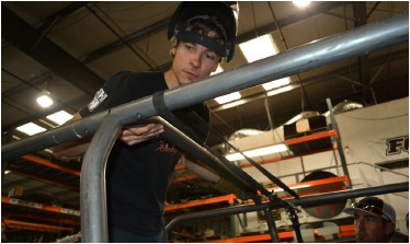
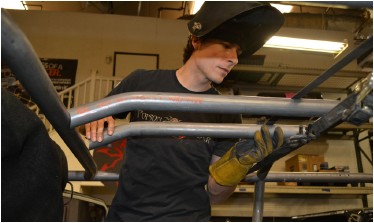
18. With the three major pieces of one side of the cage now in place (B-Pillar, Header Bar, Rear Down Bar), make sure the bolts holding the Windshield Mount Plate, B-Pillar Mount Plate and C-Pillar Mount Plate are firmly tightened, then tack-weld each of these pieces together. Be careful to use a discreetly placed tack weld at each joint, which may be easily cut out in the case something needs to be moved later. The tacks should also be placed to allow slight movement of the cage pieces in order to allow further assembly of the cage.
19. Repeat the previous steps to install the B-Pillar, Header Bar and Rear Down Bar on the passenger side.
20. Install the B-Crossbar 12 . Note that the B-Crossbar has two pairs of tab slots laser cut into the side of the tube, centered about half-way down its length. These tab slots will be oriented toward the FRONT of the Jeep when the B-Crossbar is set into place.
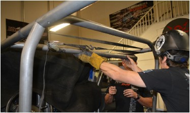
Set the B-Crossbar in place at the junction of the B-Pillar, Header Bar and Rear Down Bar, spanning from the driver side to the passenger side. Have a friend throw a ratchet strap over the Header Bar tubes to gently hold them toward each other as the B-Crossbar is tapped into place.
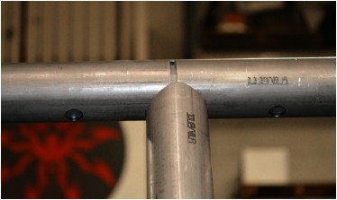
21. Set the A-Crossbar 10 in place, spanning between the two Header Bars, toward the front, near the windshield.
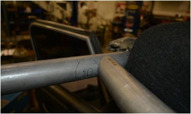
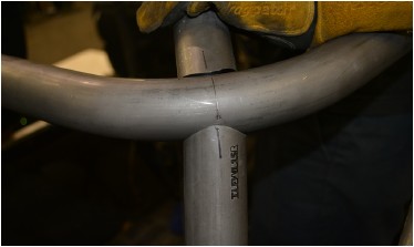
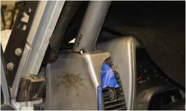
Note that the side of the Header Bar has been laser etched with a guide mark for proper placement of the A-Crossbar.
The slight bends at each end of the A-Crossbar should be oriented so that the center section of the Crossbar is bowed rearward, away from the windshield.
22. Install the two Forward Stringers 11 between the A-Crossbar and the B-Crossbar
Note that the rearward end of each Forward Stringer has laser cut tabs that fit into slots in the side of the B-Crossbar. The forward end is located using laser-etched marks in the side of the A-Crossbar.
23. Once the Forward Stringers and A-Crossbar are positioned correctly, tack them together and to the Header Bars and B-Crossbar.
24. Position the C-Crossbar 14 .The laser-cut ends are notched to fit to each Rear Down Bar, using the laser-etched alignment marks. Have a friend hold the rearward end of the C-Crossbar while you check that both ends are correctly aligned onto the cage’s Rear Down Bars.
Once the C-Crossbar is correctly positioned, with a helper continuing to support the rearward side of the tube, tack it into place. The helper must continue to support the C-Crossbar through the following step.
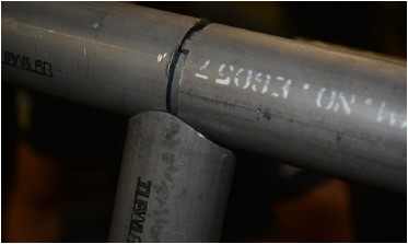
25. Position the C-Pillars 15 , one at a time, into place between the C-Crossbar and the Rear Down Bar. There are alignment marks etched into each of these tubes to properly located them.
Have the helper continue to support the C-Crossbar until both C-Pillars have been tacked into place.
26. Position the Rear Stringers 13 , one at a time, into place between the B-Crossbar and the rear corners of the C-Crossbar.
There are alignment marks etched into each of these tubes to properly locate and align them.
Once the Rear Stingers are correctly positioned, tack them in place to the B-Crossbar and C-Crossbar.
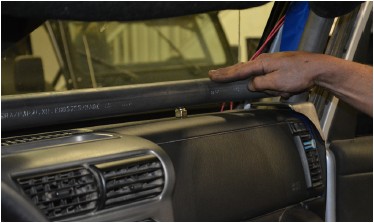
27. Position the Upper A-Pillar Tubes 7 and Dash Bar 9 , and tack them into place. This will require the help of a friend, to hold the three pieces in place while tack welding.
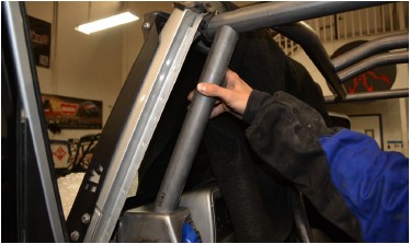
The position of the upper end of the Upper A-Pillar Tube is laser-etched into the underside of the Header Bar, however the lower end of the Upper A-Pillar Tube is not marked on the top of the Lower A-Pillar plate piece. The way they fit into the notched ends of the Dash Bar will determine the position of the lower ends of the Upper A-Pillar Tube. Use a couple of 1/2” hex nuts, set on top of the dash, to space the Dash Bar above the dash.
With all three pieces (both Upper A-Pillar Tubes and the Dash Bar) positioned, tack them into place.
28. (Optional) Install the Seatbelt Bar 16 to the rearward side of the B-Pillars. Use the laser-etched assembly marks as guides to properly locate the tube junctions. If using custom seats and belts, you may adjust the height of the Seat Belt Bar (ignoring the laser etched assembly guides) to properly locate it for your specific setup. It may be necessary to temporarily set the seats back into place to determine the optimal height. Tack the Seatbelt Bar into place.
29. At this point, all of the main cage pieces are in place and tacked together. Before starting the finish welding process, go around the Jeep and make sure the hardware on each of the mount plates that bolt to the Jeep’s tub are tightened, including:
• Windshield Mount Plates
• Lower A-Pillars
• B-Pillar Mount Plates
• B-Pillar bolts to bracket on inside of tub
• C-Pillar Mount Plates
Check that each of the junctions where cage components meet are still correctly positioned, tubes line up with the correct etched markings or notches are correctly engaged into their slots on the adjoining pieces.
30. Fully test-fit all equipment that is located within, near or around the cage or any portion of the cage. This includes soft tops, doors, seats, etc. Test each component for both fit and operation. It is EXTREMELY IMPORTANT that you verify proper fitment of all components at this time. If any tube placement needs to be adjusted, it is a simple matter of grinding the small tack welds to make any adjustments. Making these adjustments will be impossible once the cage is fully welded.
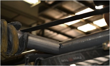
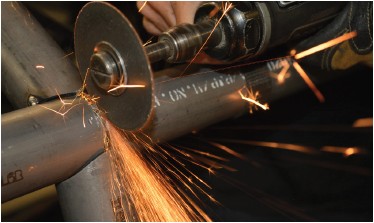
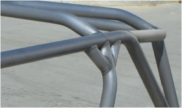
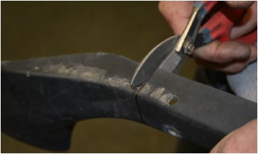
31. Where the Header Bar and Rear Down Bar meet at the top of the B-Pillar, note that there are small tangs in the ends of the tubes to provide separation of the tubes for a proper weld. These separation tangs must be cut out in preparation for final welding. Do so with a thin cut-off wheel.
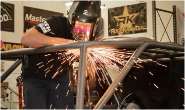
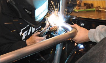
32. Finish-weld every joint on the cage. Work from side to side, welding the same joint on both sides of the cage in sequence (rather than welding all on one side of the cage, then all on the other). Be sure to do the rosette welds that hold the sleeve in place inside the Header Bar and Rear Down Bar. Weld as much as you can with the cage still bolted into the Jeep, to prevent twisting or warping of the cage.
33. At some point it will be necessary to remove the cage from the Jeep in order to reach the last few areas that need to be welded.
34. Install the 90° Gussets 20 at the junction of the B-Pillar, B-Crossbar, Header Bar and Rear Down Bar.
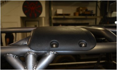
35. If re-installing the factory speaker pods, remove them from the factory roll bar, retaining the OE hardware and rubber grommets on the forward-facing threaded studs.
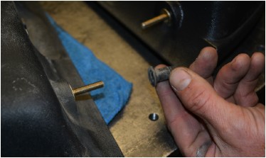
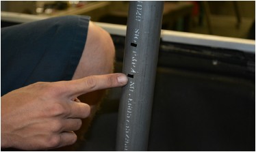
On the Poison Spyder cage there are drill locations already etched into the tubes for installing it. Pre-fit the speaker pods prior to drilling these holes. Check where the metal tang wants to poke through the B-Crossbar. IMPORTANT: There is already a laser-etched mark for this hole, however we have found that there are some year models in which this hole will need to be located slightly differently than the mark on the tube. To solve this, simply mark the tube in the proper hole location, if it is different than the pre-etched mark. Center-punch then drill this hole to 13/32”. Make sure the rubber grommet is installed on to the metal tang, and push the sound bar into place.
Make sure the two bolt holes are correctly marked on the Rear Down Bar, then remove the speaker pod, drill these holes to 7/32” and thread them with a 1/4-20 tap.
Re-install the speaker pod and use two (2) 1/4-20 X 3/4 Button Head Cap Screws with Flat Washers (hardware not included) to secure it to the Rear Down Bar.
36. If reinstalling the lower interior door moldings, they will require some trimming in order to fit around the cage A-Pillar.
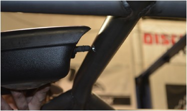
37. If re-installing the upper door surrounds for the OE soft top, there are drill marks already laser etched into the Header Bar tubes. Note that there are two center marks, which will vary depending on year model. Pre-fit your door surrounds to determine which marks are correct, then drill them out to install the door surrounds.
38. If re-installing the factory soft top bow brackets, there are drill marks etched into the sides of the B-Pillar tubes where these should be located. Drill and tap these hole locations to re-use the OE hardware.
39. Install any Poison Spyder cage options at this time, such as Entry Grab Handles or Seat Belt Mounting Kit (sold separately-follow the instructions that came with that kit).
40. Remove all pre-installed equipment, then paint or powder-coat your cage to protect it from rust. If painting it yourself, use a good quality self-etching primer on the bare steel of your cage prior to painting in the color of your choice.
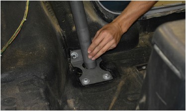
41. Re-install the cage into the Jeep and properly tighten all fasteners. Use the supplied 1/2-13 Gr8 hex head cap screws, washer plates and nylon-insert lock nuts to secure the bottom foot of each Lower A-Pillar to the existing hole in the floorboard of the Jeep.
Congratulations, you have completed the installation of your Poison Spyder Full Cage Kit!
