FREE 1 to 3-Day Delivery on Orders $149+ Details

How to Install Poison Spyder Brawler Full Width Rear Bumper w/ Tire Carrier & Hitch - Bare Steel on your Wrangler
Tools Required
- Primer, paint, cleaners and masking materials (if painting)
- Mechanic’s tool set with a full assortment of SAE and metric end wrenches, sockets, ratchets, hex keys, etc. Note: the large 1”-14 spindle lock-nut requires a 1-7/16” socket.
- Torque wrench
- Drill Motor with 1/4” & 1/2” drill bits
- Measuring tape or ruler
- Felt-tip fine point marker, scribe or punch

Shop Parts in this Guide
APPLICATIONS
These installation instructions apply to the following Poison Spyder products:
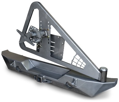
17-62-020 JK RockBrawler II Rear Bumper Tire Carrier - Tabs (shown above)
17-62-020-P1 JK RockBrawler II Rear Bumper Tire Carrier - Tabs - Black SpyderShell
17-62-050-D JK Brawler FULL Width Rear Bumper - Tire Carrier - Tabs
17-62-050-DL JK Brawler FULL Width Rear Bumper - Tire Carrier - Lights - Tabs
PARTS LIST
(1) JK RockBrawler II or Brawler FULL Width Rear Bumper with
Tire Carrier
(1) JK RockBrawler Rear Bumper Mount Hardware Kit
PN: HWKIT-17-62-010 includes:
(2) 1/2-13 X 4-1/4 Gr8 Hex Head Cap Screw
(2) 1/2-13 Gr8 Nylon Insert Lock Nut
(4) 1/2” SAE Hardened Flat Washer
(2) 3/8-16 X 1 Gr8 Hex Head Cap Screw
(2) 3/8-16 Extruded U-Nut Clip
(2) 3/8” SAE Hardened Flat Washer
(1) RockBrawler II Tire Carrier
Pre-Assembled with:
(2) Tapered Roller Bearing 1.375 ID 0.7200 Width
(1) 1”-14 Gr8 Nylon Insert Lock Nut
(1) 1” SAE Hardened Flat Washer
(1) Spyder Web Gusset Detail
(1) RockBrawler II Tire Carrier Hardware Kit
PN: HWKIT-17-62-020 includes:
(2) 3/8-16 X 1 Gr8 Hex Head Cap Screw
(2) 3/8-16 X 1-3/4 Gr8 Hex Head Cap Screw
(8) 3/8” SAE Hardened Flat Washer
(1) Tire Gate Hardware Kit
PN: HWKIT-17-62-020-1 includes:
(4) 3/8-16 Nylock Nut
(4) 1/4-20 x 1 SS BHSCS
(4) 1/4-20 Nylock Nut
(4) 1/4 SAE Hardened Flat Washer
(1) ½” Black UHMV V-Align Bushing
(1) RockBrawler II Turnbuckle Assembly
PN: HWKIT-17-62-020-3 includes (pre-assembled):
(1) 3/8-24 X 1-5/8 Aluminum Turnbuckle Connector
(1) 3/8-24 X 2-1/8 Spherical Rod End (Right Hand Thread)
(1) 3/8-24 SS Jam Nut (Right Hand Thread)
(1) 3/8-24 X 2-1/8 Spherical Rod End (Left Hand Thread)
(1) 3/8-24 SS Jam Nut (Left Hand Thread)
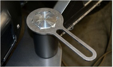
(1) Rock Brawler Pivot Cap Wrench
(1) 3-Piece Adjustable Tire & License Plate Mount Kit
Includes:
(1) Adjustable Tire Mount - Carrier Side
(1) Adjustable Tire Mount - Tire Side
(1) Adjustable License Plate Mount
(1) 3-Piece Adjustable Tire & License Plate Mount Hardware Kit
PN: HWKIT-17-61-030 includes:
(4) 7/16-14 X 1 Gr8 Hex Head Cap Screw
(4) 7/16-14 Gr8 Nylon Insert Lock Nut
(8) 7/16” SAE Hardened Flat Washer
(3) 3/8-16 X 1 Gr8 Hex Head Cap Screw
(6) 3/8” SAE Hardened Flat Washer
(3) 3/8-16 Gr8 Nylon Insert Lock Nut
(4) 1/4” SS Flat Washer
(4) 1/4-20 X 3/4 SS Button Head Socket Cap Screw
(6) 1/4-20 Gr8 Nylon Insert Lock Nut
(4) 1/4” SAE Hardened Flat Washer
(2) 1/4-20 X 3/4 Gr8 Hex Head Cap Screw
(3) 1/2-20 X 1.72/1.750 Length Wheel Lug Bolt
(3) 1/2-20 X 15/16 Hex 60° Seat Open Lug Nut
BEFORE YOU BEGIN
The Poison Spyder Customs RockBrawler™ II Rear Bumper comes as unpainted, bare steel. You will want to either powder coat or paint the bumper prior to final installation. If painting yourself, careful preparation will make a big difference in the quality and longevity of your paint job, even using “rattle can” aerosol paints. Begin by thoroughly cleaning the bumper with solvent or de-greaser, then make sure all residue is removed. Even if you use cheap paint, try to use a good quality primer. “Etching” primers are best to use on bare, unpainted metal. Allow it to properly dry before painting, and between paint coats.
INSTALLATION PROCEDURE
1. Park the Jeep on a flat, level surface and set the parking brake.
2. Remove existing rear bumper. Keep the OE hardware that attached the bumper to the frame rails, as some of it will be re-used. Disconnect the rear sway bar where it bolts to the outside of the frame rails (most aftermarket sway bars-may not be necessary with stock sway bar).
3. If the bumper and tire carrier were shipped to you with the tire carrier already installed on to the bumper, disassemble them by removing the aluminum Pivot Cap (if present), and the 1”-14 lock nut. Set the tire carrier aside, along with the lock nut, 1” flat washer, and two tapered roller bearings.
4. With the help of a friend, pre-install the bumper on to the Jeep. The bolt flanges of the bumper will mount between the outside of the frame rail and the sway bar bracket (for those Jeeps equipped with rear sway bars). Note that there are three bolt holes in the bolt flange on each side of the bumper. Two of these bolt holes will align with the stock bolt holes in the frame rail, where the sway bar bracket attaches. Use the OE bumper hardware to secure the bumper in place using these two bolt locations on either side.
5. Use a felt-tip pen or 3/8 center punch to mark the location of the third bolt hole on the frame rail, for each side.
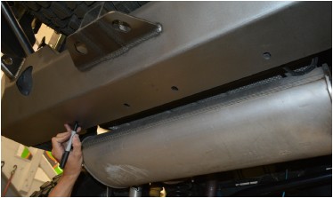
6. Look underneath the bumper, note that there are 4 bolt holes along the bottom surface of the bumper. The driver’s side, outside hole will need to be marked to drill a corresponding hole in the crossmember that sits just behind it. Use a center-punch or fine-tip felt marker to mark the hole location. You may notice that the outside passenger side already has a through-hole through the crossmember. Disregard the two center holes.
7. Remove the bumper from the Jeep.
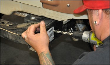
8. Drill upward through the crossmember, at the hole location marked in the previous step. Start with a smaller drill size such as 1/4”, then step up to the 1/2” bit for the final hole size. Drill through both the bottom and top surfaces of the bumper, trying to hold the drill perpendicular so the holes are vertically aligned.
9. Drill the third bolt hole on the sides of each frame rail to 1/2”. It is best to start with a smaller drill size such as 1/4”, then step up to the 1/2” size bit.
10. Apply touch-up paint to the bare metal around the edge of the holes that were drilled in the previous steps. Properly coating these areas at this time will help to prevent rust in the future.
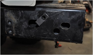
11. Insert a 3/8-16 Clip Nut through the oblong-shaped hole in the frame rail, and clip it into the new hole just drilled. Make sure the extruded thread barrel of the clip nut points inward. Do this on both frame rails.
12. Reinstall the bumper using the OE hardware in the two original bolt locations on the sides of the frame rail, and a supplied 3/8-16 X 1 Gr8 Hex Head Cap Screw with 3/8 Flat Washer in each of the new bolt locations on the outside of the frame rails. Note that both the bumper’s mount flanges should be inserted between the outside of the frame rail and the sway bar bracket (if sway bar is present).
13. Insert the 1/2-13X4-1/4 Gr8 Hex Head Cap Screws into the two outside holes along the underside of the bumper, with a 1/2 Gr8 Flat Washer under the bolt head. Insert the bolt up through the holes in the bumper and both top and bottom surfaces of the crossmember. Secure them with a 1/2-13 Gr8 Nylon Insert Lock Nut and 1/2 Gr8 Flat Washer, where they protrude through the top of the crossmember. You may have to do this by feel, as you won’t be able to see the locations of the nuts and washers up inside the bumper shell.
14. If the optional 2-1/2” LED backup lamps were purchased, use the provided rubber grommets to mount them into the recessed mounting flanges inside the backup lamp buckets. Use the electrical pigtails that came with the lamps, along with wire and connectors (not included) to wire the backup lamps in to your Jeep’s backup lamp circuit.
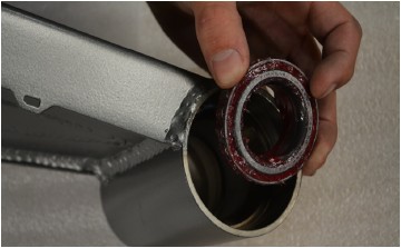
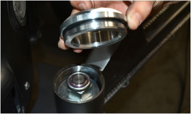
15. Wearing latex or nitrile gloves, “Pack” the two tapered roller bearings with a quality wheel bearing grease by hand or with a bearing packing tool. The two matching bearing races are already pressed in to the tire carrier hinge housing.
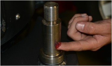
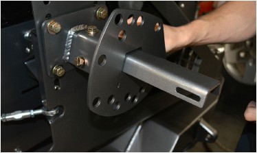
16. Apply a light sheen of grease to the bare metal surfaces of the inside of the tire carrier pivot housing and bearing races, as well as the hinge spindle on the bumper (do not coat the threads for the spindle nut). This will help discourage rust formation on these bare metal surfaces.
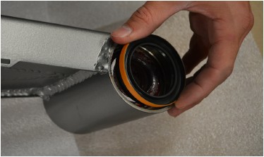
17. Insert a Tapered Roller Bearing into the pre-installed Lower Race, inside the Hinge Housing. Ensure that it seats correctly and “feels right” in the race. Excess grease may hold it in place temporarily, but it may be helpful to turn the tire carrier upside down until the next step is completed.
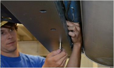
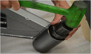
18. Use a bearing seal driver tool to carefully install the grease seal into the bottom of the hinge housing. If the proper tool is not available, the step may be performed by carefully using a large socket of the approximate diameter of the seal and a soft dead-blow hammer to work the seal into its seat. Be very careful to drive the seal in evenly, do not let it get misaligned while driving it in.
19. Install the Tire Carrier onto the bumper, carefully guiding the hinge housing down over the hinge spindle. Be careful not to damage the grease seal when lowering the tire carrier on to the spindle. There is a very tight-tolerance slip-fit between inner diameter of the tapered roller bearing and its seating surface on the spindle. Be careful not to let the bearing get misaligned as you lower the carrier onto the bumper. Have a friend support the opposite end of the tire carrier during this and the next two steps.
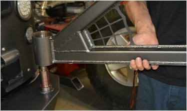
20. Install the remaining Tapered Roller Bearing by dropping it down over the hinge spindle, narrow end pointed downward. Carefully slide it down the spindle until it is seated into the upper race.
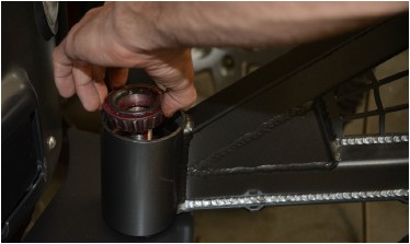
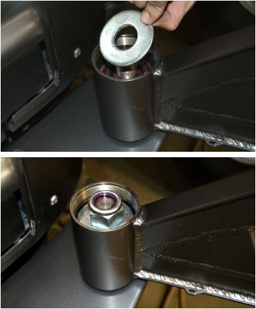
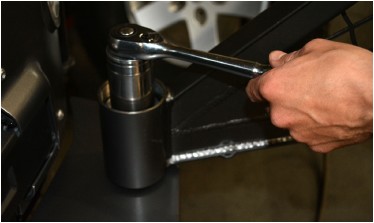
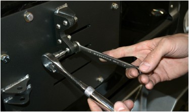
21. Apply some anti-sieze thread lubricant to the threads on the spindle. Install the large 1” Flat Washer next on the spindle, followed by the 1”-14 Lock Nut. Tighten the lock nut until it just touches the washer and bearing, then have your friend slowly swing the tire carrier back and forth as you tighten the lock nut the rest of the way.
We can not supply a torque specification for this nut, just get it as tight as it takes to properly seat the bearings and provide smooth operation of the tire swing without any “play”. Re-tighten this nut after the weight of the spare tire and accessories have been added, and again after a few days or a hundred miles of use. You may need to re-tighten this nut several more times until it permanently seats.
22. Install the Pivot Cap O-Ring onto the outside of the threads of the Billet Hinge Cap, just under the head of the cap (NOTE: this may have already been done prior to shipment).
23. Thread the Hinge Cap onto the Hinge Housing and lightly tighten with the provided Pivot Cap Wrench. Note that you may have to remove it in later steps to further tighten the spindle lock nut, so don’t fully tighten the cap until installation is complete.
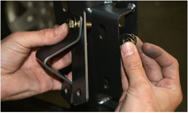
24. Use the OE Spare Tire Mount hardware to attach the Tailgate Plate to the tailgate. The TailGate Plate must be oriented so the welded-on brackets are toward the top and driver side.
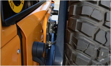
25. Install the 1/2” Black UHMW V-Alignment Bushing on to the corresponding bracket on the Tailgate Plate using the supplied hardware, as shown.
26. Install the V-Alignment Plate on to the back side of the Tire Carrier using the supplied hardware.
27. Test that it seats correctly into the V-Alignment Bushing on the Tailgate Plate when the Tire Carrier is closed against the tailgate. Adjust as necessary then tighten all fasteners.
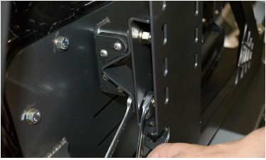
28. Assemble the Aluminum Turnbuckle, Spherical Rod Ends and SS Jam Nuts into a tie-rod assembly. Note that there are left hand threaded and right hand threaded ends of the turnbuckle, rod ends and nuts. (NOTE: the Turnbuckle Assembly may have already been pre-assembled at Poison Spyder). Use the provided hardware to attach one end of the tie rod to the Tailgate Plate, and the other end to the corresponding tabs in the back side of the Tire Carrier, as shown.
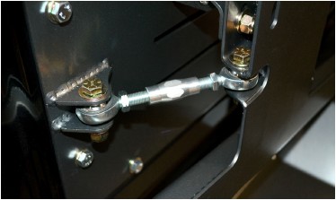
29. Leave the jam nuts on the turnbuckle loose, and adjust the length of the tie rod by rotating the turnbuckle. Adjust the length so that the V-Alginment Plate just begins to touch the V-Alignment Bushing when the tailgate is about 1/2” from being fully closed and latched. This is approximately the point at which the tailgate begins to compress the weatherstripping as it closes. With the tie rod adjusted thusly, test it by firmly (but carefully) closing the tailgate all the way, until it latches. When properly adjusted, this will result in the tie rod firmly pulling the V-Alignment Plate into the V-Bushing, and holding it there with enough pre-load to keep everything tight while the tailgate is shut. Once the tie rod has been properly adjusted, tighten both jam nuts.
30. Measure the overall height of your spare tire (NOT one of the mounted tires on your Jeep!), divide that measurement in half, then add one inch. The resulting number will be your Tire Mount Height measurement. With the tire carrier closed and latched, measure upward from the recessed step surface of the bumper, and make a small mark on the tire carrier at the tire mount height measurement.
31. Use (4) 7/16-14 x 1 Gr8 Hex Head Cap Screws with (4) 7/16 Flat Washers and (4) 7/16-14 Nylon Insert Lock Nuts to attach the Tire Mount - Carrier Side to the Tire Carrier, centered on the mark you made in the previous step. The slots in the tire carrier allow for some adjustment, however if there isn’t enough adjustment to center the Tire Mount exactly centered on your mark, move it up slightly to the next set of slotted holes in the carrier. Tighten the four bolts/nuts to approximately 50 ft.-lbs.
32. Look at the Tire Mount - Tire Side, and note that there are wheel stud holes for several different bolt patterns. Use the Bolt Pattern Template provided at the end of these instructions to determine which THREE holes to use for your specific bolt pattern. Once the three holes are correctly identified, mark them with a felt-tip marker.
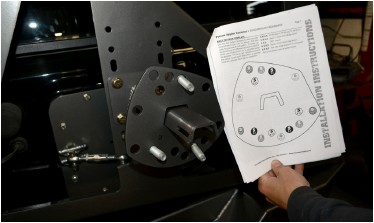
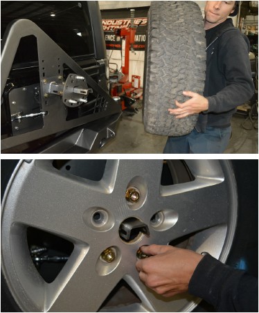
33. Use a shop press or hammer to drive the three provided Wheel Studs into the mounting plate, using the holes that were marked in the previous step. Make sure the studs point in the opposite direction from the V-channel piece that is welded to the back of the plate.
34. Lay your spare tire on the floor with the mounting surface of the wheel pointed up. Lay a long straight edge (yardstick, level, or other suitable item) across the middle of the tire. Measure the vertical distance from the straight edge to the wheel mounting surface. This is the Overall Offset measurement, including any bulge in the tire sidewall.
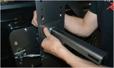
35. Fit the Tire Mount - Tire Side channel on to the corresponding beam of the Tire Mount - Carrier Side. Use (3) 7/16-14 X 3 Gr8 Hex Head Cap Screws with (6) 7/16 Flat Washers and (3) 7/16-14 Nylon Insert Lock Nuts to secure the Tire Mount-Tire Side to the Tire Mount - Carrier Side, using the slotted holes provided. Adjust the position of the mounting surface of the distance between the Tire Mount and the surface of the tire carrier frame is 1/4 to 1/2 inch LESS THAN the Overall Offset measurement found in the previous step. Once properly adjusted, tighten the three bolts/nuts to approximately 50 ft.-lbs.
NOTE: Some tire/wheel combinations, such as 12.50 wide tires on stock Jeep wheels, may require more Overall Offset than the adjustment in the Tire Mount components allows (approximately 4-3/4” to 6-3/4”). In these cases, source a wheel spacer of suitable thickness to make up the difference.
36. Lift the spare tire onto the Tire Mount - Tire Side, and fit the previously installed lug studs through the holes in the wheel. Tighten the (3) Lug Nuts. This will draw the sides of the tire tightly against the frame of the Tire Carrier, to prevent rattles and squeaks.
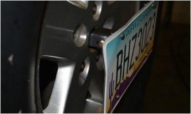
37. Use (4) 1/4-20 X 3/4 SS Button Head Cap Screws, (4) 1/4 Flat Washers and (4) 1/4-20 Nylon Insert Lock Nuts to fasten your license plate to the License Plate Mount.
38. Use the 1/4-20 X 3/4 Hex Head Cap Screws with 1/4 Flat Washer and 1/4-20 Wing Nut to fasten the License Plate Mount to the Tire Mount at the center of the spare tire. Note that you will need to keep these wrenches available in the vehicle in order to remove the license plate mount to access your spare tire in the future.
39. If required by law in your area, you will need to install a license plate light to illuminate the plate at night. Poison Spyder sells separately an LED License Plate & Third Brake Light (p/n 41-04-LP6) that is designed specifically for this purpose, and comes with a 6’ lead to route down the tire carrier to tie into the Jeep’s wiring. Instructions for making the electrical connections are outside of the scope of these instructions, however please note that the tire carrier has small loops laser-cut into the tire carrier swing to make routing and securing the license plate light easy. Simply secure the extension cable to these loops with zip-ties to securely hold it in place.
40. Once the entire bumper is mounted and tested for proper operation, remove and disassemble the bumper for paint or powder coat. If painting yourself, careful preparation will make a big difference in the quality and longevity of your paint job, even using “rattle can” aerosol paints. Begin by thoroughly cleaning the bumper with solvent or de-greaser, then make sure all residue is removed. Even if you use cheap paint, try to use a good quality primer. “Etching” primers are best to use on bare, unpainted metal. Allow it to properly dry before painting, and between paint coats. Note that the Spyder Web Gusset Detail is detachable so that it may be painted or powder coated a contrasting color from the rest of the bumper.
If powder coating, make sure the entire bumper and tire carrier are completely disassembled first. Make sure the bearings, races and grease seal are not yet installed. Make sure your powder-coater understands that the hinge spindle must be masked off (not coated).
41. Once the bumper has been painted or powder coated, re-install by repeating the above steps. On Brawler FULL Width Rear Bumpers with provisions for mounting recessed LED pod lights, pre-install the LED lights into the bumper prior to re-installing the bumper on to the Jeep. On RockBrawler II Rear Bumpers, 2-1/2” round LED backup lamps (sold separately) may be installed after the bumper has been installed on to the Jeep.
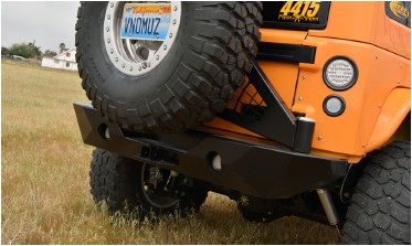
Congratulations, you have completed installation of your RockBrawler™ II or Brawler FULL Width Rear Bumper and Tire Carrier!
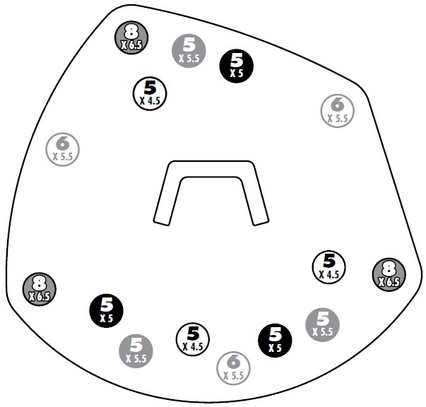
BOLT PATTERN TEMPLATE
Use this Bolt Pattern Template to determine the correct holes to use in the Tire Mount - Tire Side plate, for your specific bolt pattern. The plate can be used for any of 5 different bolt patterns, each of which uses 3 holes which can be identified using the template. The list at right identifies some of the vehicle models each bolt pattern is typically used with, although there may be exceptions.
5 X 4.5 ‘87-’96 Jeep YJ, ‘97-’06 Jeep TJ, ‘84-’01 XJ
5 X 5.5 Jeep CJ, 1/2-ton Ford & Dodge trucks*
5 X 5 2007 Jeep JK
6 X 5.5 Toyota, 1/2-ton Chevy & Jeep trucks*
8 X 6.5 Ford, GM, Dodge & Jeep 3/4- & 1-ton trucks*
*Prior to converting to metric for various models