 FREE 1 to 3-Day Delivery on Orders $149+ Details

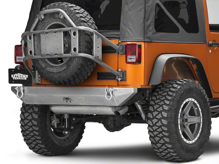
How to Install Poison Spyder Body Mount Tire Carrier - Bare Steel on your Wrangler
Installation Time
2 hours
Tools Required
- Primer, paint, cleaners and masking materials (if painting)
- Mechanic's tool set with a full assortment of SAE and metric end wrenches, sockets, ratchets, hex keys, dead-blow hammers, etc.
- Drill Motor with assorted drill bits
- Felt-tip fine point marker or scribe
- Auto-punch or transfer punches and hammer
Shop Parts in this Guide
APPLICATIONS
These installation instructions apply to the following Poison Spyder products.
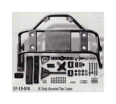
PARTS LIST
Please check your packages immediately upon arrival to ensure that everything listed is included, and to check for damage during shipping. If anything is missing or damaged, call Poison Spyder at (951) 849-5911 as soon as possible.
JK Body Mounted Tire Carrier (Main Structure)
Latch Plate
Latch Plate Drill Template
Upper Internal Brace
Upper Internal Brace Clamp Plate
Lower Internal Brace
JK License Plate Delete Cover
Threaded Tire Mount
Tire Mount Wing Nut
Tire Mount Centering Cone
Upper Hinge Bracket
Lower Hinge Bracket
T-Lock Latch Assembly
T-Lock Spacer Ring
Black Delrin Bushing
3/4" Inner Bushing Sleeve
1/2" Swing-Stop Sleeve
Upper Adjustment Cam Nut
Lower Adjustment Cam Nut
Rubber Insert Bumper
Alignment Cone SS
Middle-Upper Latch Plate Spacer - 5/8 O.D. X .226"
Middle-Lower Latch Plate Spacer - 5/8" O.D. X .257"
Lower Latch Plate Spacer - 5/8" O.D. X .257" X .562"
JK Body Mounted Tire Carrier Hardware Kit
PN: HWKIT-17-13-010 Includes:
(6) 3/8-16 X 1.1/2 Gr8 Hex Head Cap Screw
(3) 3/8.16 X 1 Gr8 Hex Head Cap Screw
(9) 3/8.16 Gr8 Nylon Insert Lock Nut
(18) 3/8" SAE Hardened Flat Wosher
(2) 1/2-13 X 4.1/2 SS Socket Head Cap Screw
(1) 1/2-13 SS Nylon Insert Lock Nut
(2) 1/2" Small ID SS Flat Washer (2) M10-1.5 X 100 SS Socket Head Cap Screw
(4) M10 SS Flat Washer
(2) M10-1.5 SS Nylon Insert Lock Nut
(4) 5/16-18 X 3/4 SS Socket Head Cap Screw
(11) 1/4-20 SS Nylon Insert Lock Nut
(16) 1/4" SAE Hardened Flat Washer
(2) 1/4-20 X 1-1/4 SS Flat Head Cap Screw
(4) 1/4-20 X 3/4 SS Button Head Cap Screw
(5) 1/4-20 X 1 SS Button Head Cap Screw
(4) 1/4" SAE SS Flat Washer
BEFORE YOU BEGIN
IMPORTANT Completely install and remove the product BEFORE painting or powder coating it. This will allow you to check for fitment or do any clearancing or fitting ahead of time, to reduce the chance of damage to the finish during final installation. Poison Spyder Customs Inc. is not responsible for costs for or damage to paint or powder coat finish under any circumstances, including paint or powder coat of incorrectly shipped or defective parts.
Several components of the JK Body Mounted Tire Carrier come as unpainted, bare steel. You will want to either powder coat or paint these items prior to final installation. If painting yourself, careful preparation will make a big difference in the quality and longevity of your paint job, even using "rattle can" aerosol paints. Begin by thoroughly cleaning the bumper with solvent or de-greaser, then make sure all residue is removed. Even if you use cheap paint, try to use a good quality primer "Etching" primers are best to use on bare, unpainted metal. Allow it to properly dry before painting, and between paint coats.
INSTALLATION PROCEDURE
1. Park the Jeep on a flat, level surface and set the parking brake. Wear safety glasses from this point forward.
2. Remove the stock spare tire carrier if it is present. It is recommended that a Poison Spyder Tramp Stamp or Tramp Stamp II be installed in its place to clean up the appearance of the tailgate, however this is not necessary for installation of the tire carrier.
3. Use a 7mm nut driver to remove the license plate from the stock license plate holder if it is present. Remove the plastic license plate holder from the Jeep.
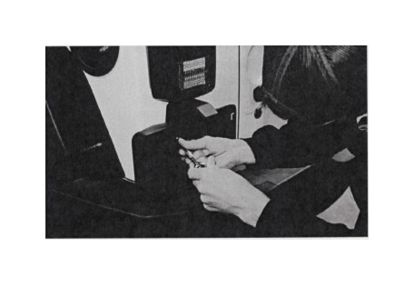
4. With the license plate holder unbolted, disconnect the license plate light pigtail from the Jeep's wiring harness by pressing on the release tab on the plastic connector, and pulling them apart.
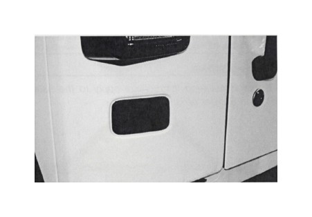
5. Tuck the Jeep's wiring harness back into the Jeep, pop out the plastic screw retainers, and install the License Plate Delete Cover into the hole left in the Jeep's body.
6. Use a Phillips head screw driver to remove the side taillight assembly. It is only necessary to remove the screws from the top-inside and bottom-inside corners. The two screws in the outside corners may be left in place. With the screws removed, grasp the taillight assembly and gently shift it toward the inboard side of the Jeep and pull it away.
7. Disconnect the taillight assembly from the Jeep's vehicle wiring harness by pressing the release tab and separating the two plastic plugs. Set the taillight aside.
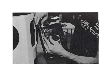
NOTE: Some of the following photos were shot out of sequence and depict the taillight still in place. Please disregard the presence of the taillight in the following shots.
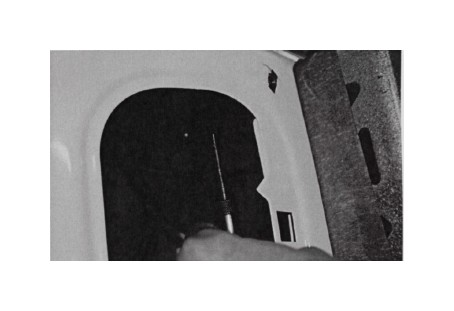
8. Find "THIS SIDE UP" etched into the Latch Plate Drill Template. Hold the template up to the Jeep's body, between the taillight and the tailgate, with the letters away from the Jeep and the arrow pointing up as shown.
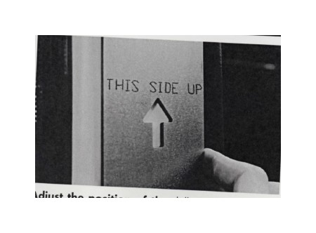
9. Adjust the position of the drill template so that the bottom edge is even with the point where the body tube begins to curve inward. Align the right side of the template approximately so that it is even with the point where the small curve begins at the edge of the tailgate opening. Use a fine-tip felt marker to mark each of the hole locations in the template.

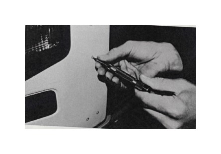
10. Use an auto-punch or manual punch with a small hammer to punch the hole locations. You're just creating a small indentation for the drill to start in without wandering—don't try to punch all the way through. And try not to hit the sheet metal hard enough to dent it other than the small indent needed to pilot the drill.
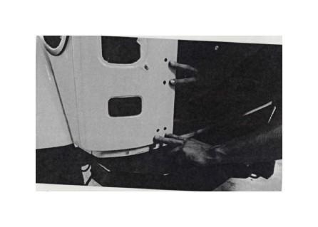
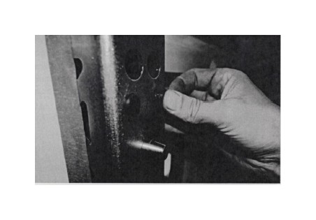
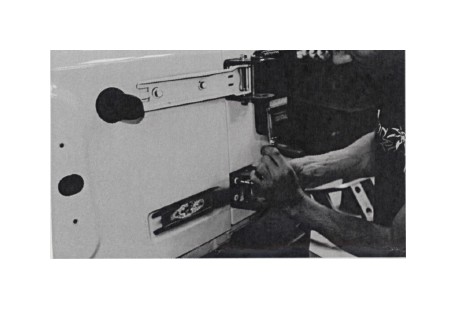
11. Drill each of the six hole locations to a finished hole size of 25/64", through both the outer and inner sheet metal walls. It is recommended to start with a pilot hole of around 3/16" before stepping up to the 25/64" finished hole size. Be careful when drilling, as the sheet metal is very thin and may want to catch on the drill flutes. Note that the body tub in this location is double-wall, so you will be drilling through two layers of sheet metal.
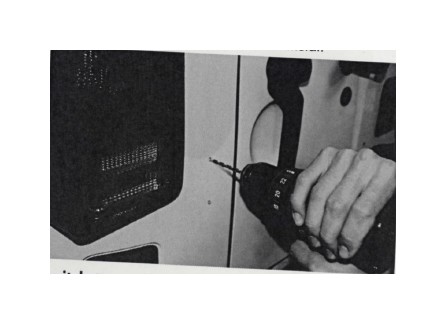
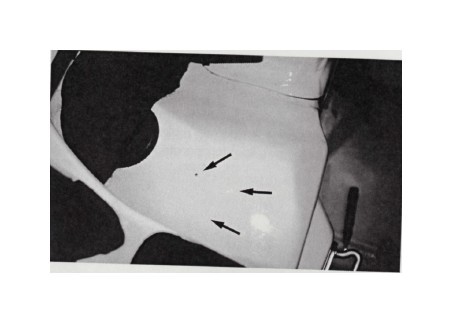
12. Switch to a 5/8" drill bit and drill ONLY the outer layer of sheet metal to 5/8", for ONLY the two lower and two center holes (as shown in the following photo—all except the top two holes). Remember to drill ONLY the outer layer of sheet metal with the 5/8" bit. Again, drill carefully as the sheet metal is thin and may want to grab the drill flutes.
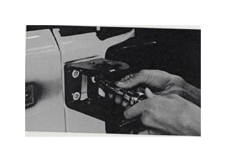
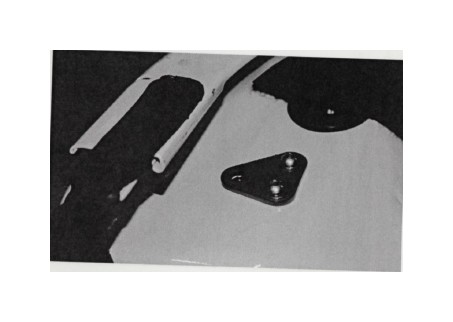
13. In the hardware pack, find the (2) Alignment Cones SS, (2) 1/4-20 X 1-1/4 Flat Head Cap Screw SS, (2) 1/4-20 Nylon Insert Lock Nut SS, and (2) 1/4 Gr8 Flat Washer. Use the Flat Head Cap Screws, washers and lock nuts to attach the Alignment Cones to the front side of the Latch Plate as shown.
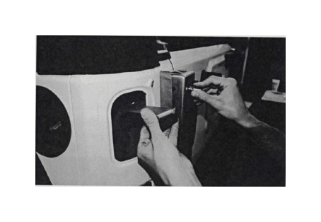
Insert the flat head screw into the narrow end of the cone, then through the small holes at the top and bottom of the Latch Plate.
On the back side of the latch plate, a corresponding larger hole is provided to allow access with a 7/16" deep socket to install and tighten the flat washer and lock nut. Use a 5/32" hex key to hold the flat head screw in place while tightening the nut.
14. Install the (4) Rubber Insert Bumpers in the provided holes just above each of the Alignment Cones. Use a dab of grease to help them slip into place. (Note: photos depict this step out of proper sequence)
15. As this is a pre-installation, and the components will be removed for paint or powder-coat prior to final installation, apply some masking tape to the back side of the Latch Plate to protect the Jeep's paint finish during the pre-installation process.
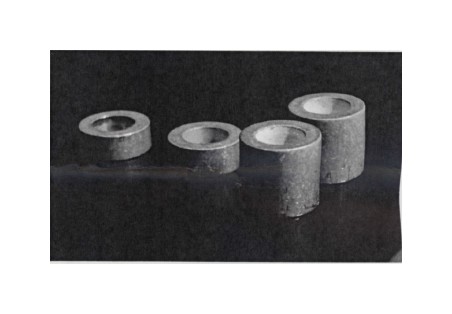
16. Locate the four aluminum Latch Plate Spacers that came in your hardware kit. The two tallest spacers are .562" thick, they will be used with the two lower Latch Plate bolts. The remaining two spacers are nearly identical but one is slightly thicker than the other. Of these, the thicker one, which is .257" thick, is used with the middle-lower Latch Plate bolt. The remaining spacer, which is the thinnest one at .226", is used with the middle-upper Latch Plate bolt.
17. Pre-install the (6) 3/8-16 X 1-1/2 Gr8 Hex Head Cap Screws from the inside of the Latch Plate, as shown in the following photo. Hang the Latch Plate Spacers onto the protruding ends of the bottom, middle-lower and middle-upper bolts as shown.
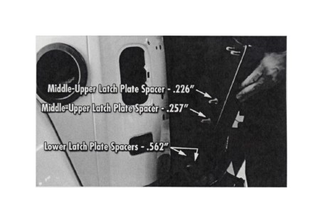
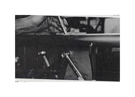
18. Carefully install the Latch Plate assembly on to the Jeep, guiding the threaded ends of the Cap Screws, and the Spacers, into the holes drilled in the previous steps. It may be advantageous to use a small piece of tape over the bolt heads inside the Latch Plate, to help keep them in place. Once the Latch Plate is in place, install 3/8" Flat Washers and 3/8-16 Lock Nuts on to the threads of the middle-upper and middle-lower cap screws, where they protrude into the corner cavity of the Jeep, behind the taillight hole.
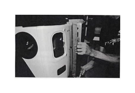
Use a 9/16" socket with ratchet and a 9/16" box end wrench (inside of the body tub) to tighten these bolts. Tighten until the bolts are just barely snugged, so that the Latch Plate may still be shifted from side to side on the elongated bolt holes. DO NOT over-tighten these bolts. They will be further tightened in a later step.
IMPORTANT Be careful not to let the upper and lower 3/8-16 Cap Screws fall out of place before getting the washers and nuts on to them in the next steps. If the bolts fall out, you risk the Spacers falling down between the two layers of body sheet metal. They would be almost impossible to retrieve.
19. Install the Upper and Lower Latch Plate Braces. In the following illustration, we've made the Jeep's body tub transparent to show how these pieces fit together inside the corner cavity of the body:
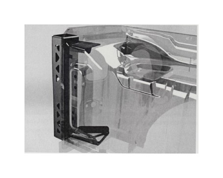
The taillight hole allows access to the interior cavity of the body tub as shown in the following photo. Each of the Latch Plate Braces attaches to the Latch Plate (with the Jeep's body panel sandwiched between) with (2) 3/8-16 X 1 1/2 Gr8 Hex Head Cap Screws which were inserted in a previous step, with 3/8" Flat Washers and 3/8-16 Lock Nuts. Use a 9/16" socket with ratchet and a 9/16" box end wrench (inside of the body tub) to tighten these bolts. Tighten until the bolts are just barely snugged, so that the Latch Plate may still be shifted from side to side on the elongated bolt holes. DO NOT over-tighten these bolts. They will be further tightened in a later step.
The Upper Latch Plate Brace will be bolted to the inner body tub panels later in the installation process.
20. Peak through the taillight hole and observe the Lower Internal Brace that was partially installed in the previous step. Install (2) 1/4-20 X 1 Button Head Cap Screws SS, with Flat Washers and lock nuts, to secure the Brace, using two existing holes in the floor of the cavity in the body tub. Tighten these bolts until just before they go snug, so that the Brace may still move around slightly as further adjustments to the Tire Carrier are made in later steps.
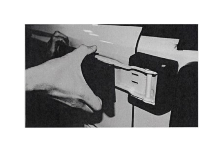
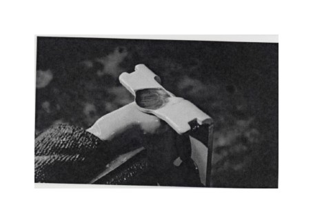
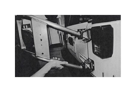
21. Remove the plastic tailgate hinge covers. The long cover may be removed by firmly grasping it near the pivot side of the hinge, squeezing, and sliding it to the left.
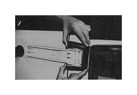
22. Remove the short tailgate hinge covers by spreading the top and bottom apart, as shown in the photo below.
IMPORTANT In the following steps we will be removing each tailgate hinge and modifying it, one at a time beginning with the upper hinge. Make sure the tailgate is firmly shut and latched before proceeding. Do not remove the lower hinge until the upper hinge has been modified and reinstalled. DO NOT OPEN THE TAILGATE until BOTH hinges have been modified and reinstalled.
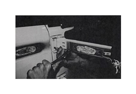
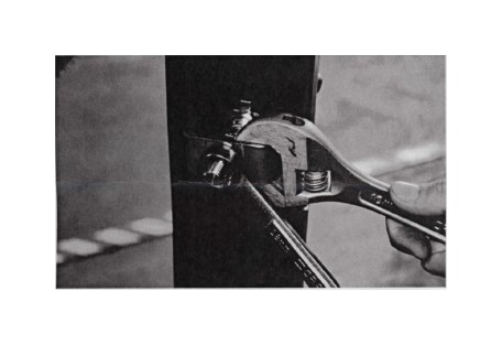
23. Make sure the tailgate is firmly shut and latched, then use a 13mm wrench to remove the two bolts from the tailgate side of the upper hinge. Proceed with a T47 Torx bit to remove the 3 hinge bolts from the body side.
IMPORTANT Make sure the Torx bit is firmly seated into the head of the bolt. Pooled paint may prevent the bit from fully seating, but a light tap with a mallet will ensure full engagement. If the bit isn't fully seated, there is a risk of stripping the bolt head, the driver bit, or both.
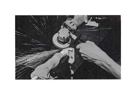
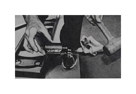
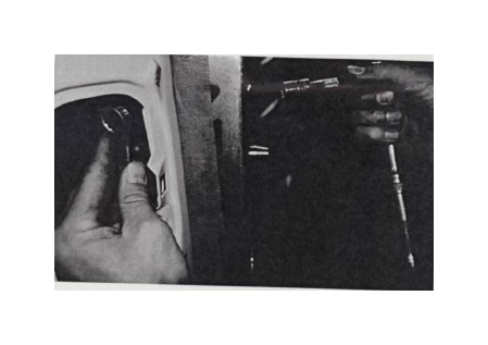
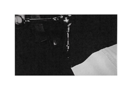
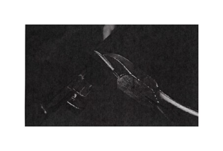
24. Inspect the hinge assembly and note that the hinge pin has a thick head on one end, and a thin head on the other. Place the long side of the hinge into a vise as shown, with the thin hinge pin head oriented upward. Use a shop rag to protect the paint on the hinge.
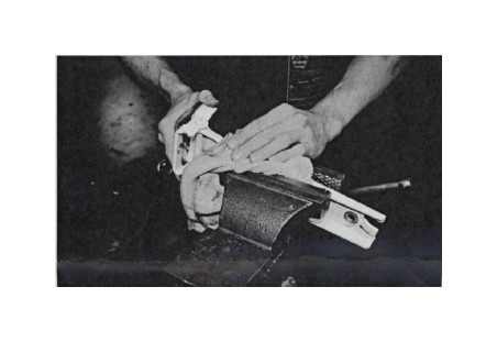
25. Try not to grind too far into the hinge piece itself, although some slight grinding into it is inevitable in order to fully remove the pin head.
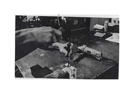
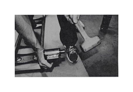
26. Use a narrow punch and shop hammer to pound the hinge pin out of the hinge.
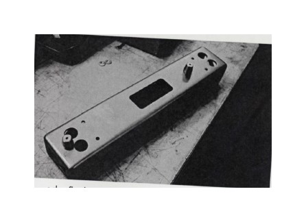
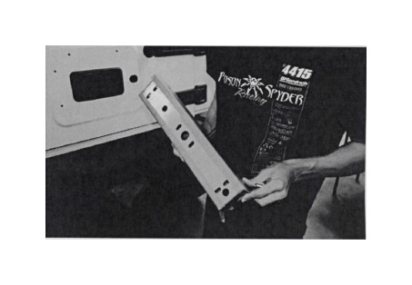
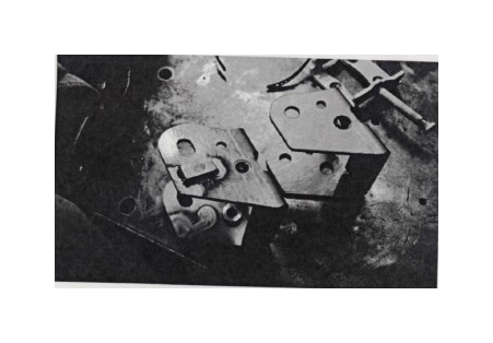
27. Observe the two hinge brackets provided in the kit, as shown in the photo below. The Upper Hinge Bracket is the one with the slotted hinge pivot holes and cam stop blocks welded to the outside (the one on the left in the photo).
28. Install the Upper hinge Bracket on to the Jeep, re-using the three Torx bolts that were removed when the hinge was removed.
29. Reinstall the long side of the hinge using a M10-1.5 X 100 Socket Head Cap Screw (8mm hex key) as the new hinge pin. Secure it with an M10-1.5 lock nut (17mm wrench) and flat washers top and bottom.
30. Install a 1 /2" diameter Swing Stop Sleeve into the Upper Hinge Bracket as shown, using two 5/16-18 X 3/4 Socket Head Cap Screws (1/4" hex key). At final assembly, apply blue thread locker (Loctite® 242 or equivalent) to the threads.
31. Reinstall the OE bolts that attach the long side of the hinge to the tailgate (13mm wrench).
32. Repeat the previous procedures with the lower hinge: hinge removal, grind and remove hinge pin, install Lower Hinge Bracket, reinstall long side of hinge, install Swing Stop Sleeve.
33. Install the four (4) Black Delrin Bushings into the tube hinge sleeves on the Tire Carrier Main Structure. Use a round file to make sure the ends of the tube sleeves are free of burrs. Apply a thin film of grease to the bushing, then tap into place with a mallet.
34. Insert a 3/4" Inner Bushing Sleeve into the tire carrier hinge bushings installed in the previous step. Before inserting, de-burr and round over any sharp edges at the ends of the sleeve with a file. Apply a thin film of grease to the sleeve, then tap it into place with a mallet. Do this for both the upper and lower bushing/hinge assemblies on the tire carrier.
35. With the help of a friend, lift and install the Tire Carrier Main Structure into the Upper and Lower Hinge Brackets.
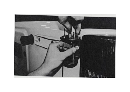
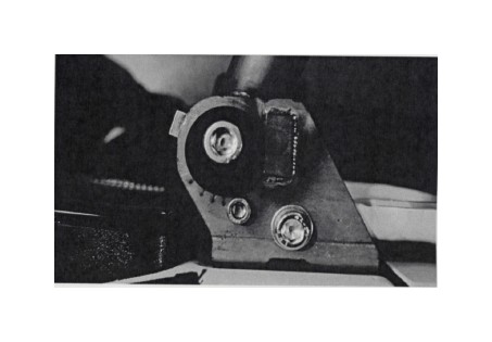
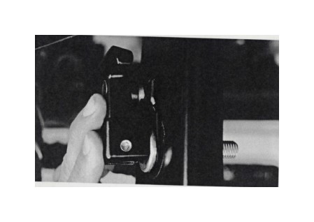
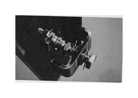
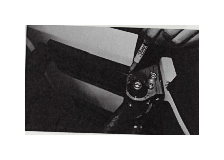
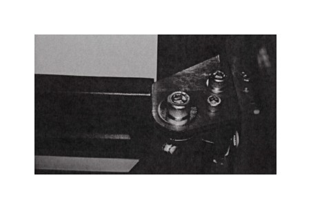
36. Locate the Upper Adjustment Cam. It is the one that is NOT threaded, and is counter bored to accept the head of a 1/2-13 X 4-1/2 Socket Head Cap Screw as shown in the photo below.
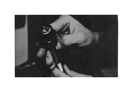
Insert the 1/2-13 X 4-1/2 Socket Head Cap Screw, through the Upper Adjustment Cam, into the Upper Hinge Bracket and through the bushing sleeve.
Thread the Lower Adjustment Cam Nut onto the end of the 1/2-13 bolt, where it protrudes through the bottom of the Hinge Bracket. Leave this assembly finger-tight for now.
37. Install a 1/2-13 X 4-1/2 Socket Head Cap Screw, with 1/2-13 lock nut and washers, into the lower hinge assembly and tighten with a 3/8" hex key and 3/4" wrench.

38. Install the license plate to the center plate of the Tire Carrier Main Structure, using (4) #10-24 X 3/4 Button Head Cap Screw SS (1/8" hex key), Flat Washers and Lock Nuts (3/8" wrench).
39. If laws in your area require the license plate to be illuminated, install a license plate light of your choice. Poison Spyder recommends its LED License Plate Light & 3rd Brake Light with 6' Extension Harness (p/n 41-04-LP6).
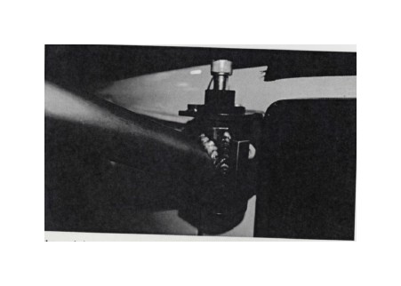
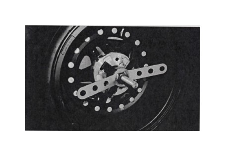
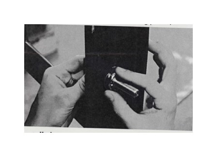
40. Attach the Threaded Tire Mount to the inside of the Tire Carrier Main Structure, using (3) 3/8-16 X 1 Gr8 Hex Head Cap Screws, Lock Nuts and Flat Washers.
Use a pair of 9/16" wrenches to tighten the three 3/8-16 X 1 Hex Head Cap Screws, Flat Washers and Lock Nuts.
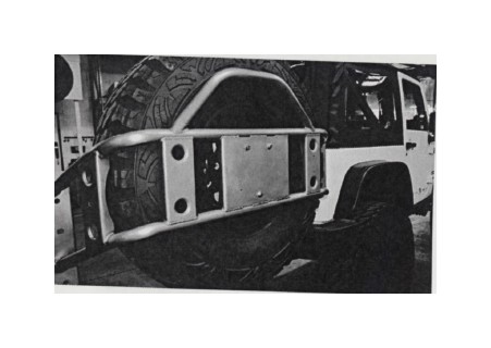
41. Lift the spare tire onto the Tire Carrier, with the outside (appearance side) of the wheel facing the back of the Tire Carrier (facing away from the Jeep with the Tire Carrier closed).
42. Slide the Tire Mount Centering Cone on to the Threaded Tire Mount, followed by the Tire Mount Wing Nut. Thread the Wing Nut down until it is snug against the tire. The tire may need to be lifted slightly as the Wing Nut is tightened, so that the Cone may properly center the tire. Once the tire is centered, tighten the Wing Nut as far as it can reasonably be tightened by hand.
43. Pre-Install Any Roto-Pax accessories and/or Hi-Lift Jack (see notes in steps 60 & 61). Make sure Roto-Pax units are full, as they will be in normal use.
44. Once the spare tire and any accessories are installed, close the Tire Carrier and note that the Alignment Cones in the Latch Plate are most likely not correctly aligned with their corresponding holes in the Tire Carrier Main Structure.
There are two adjustments that must be made to perfectly align the Alignment Cones. To adjust them left to right, simply shift the Latch Plate left or right, as the bolts mounting it to the Jeep's body are in slotted holes, and not yet fully tightened. The following procedure is for aligning the holes with the Cones vertically, which is done at the Adjustment Cams on the Upper Hinge at the other side of the Tire Carrier.
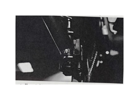
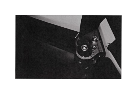
45. Note that there are hash marks etched into the Upper Hinge Bracket, with an indexing mark etched into the Upper Adjustment Cam. The same markings can be found on the Lower Hinge Bracket and the Lower Adjustment Cam Nut. Make sure the Upper and Lower Adjustment Cams are clocked the same (index marks on the Cams point to the same hash marks on the top and bottom side of the Hinge Bracket). Note that at this point the large Socket Head Cap Screw that runs through the Upper Hinge Assembly should not be fully tightened yet.
46. With a 1" wrench on the Upper Adjustment Cam and a 3/4" wrench on the Lower Adjustment Cam, rotate them TOGETHER to raise or lower the opposite side of the Tire Carrier, until properly aligned with the Alignment Cones in the Latch Plate.
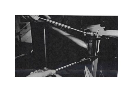
Remember that adjustments to align the Cones side-to-side are made by shifting the Latch Plate left or right. Adjust the side-to-side positioning of the Latch Plate and the Adjustment Cams simultaneously until the Alignment Cones seat perfectly into the holes in the Tire Carrier, allowing the Tire Carrier to shut fully against the Latch Plate.
47. Once the alignment Cones are properly aligned with the corresponding holes in the Tire Carrier, tighten the Upper Hinge assembly by holding the Lower Adjustment Cam Nut stationary with a 3/4" wrench while tightening the large Socket Head Cap Screw with a 3/8" hex key or driver bit. Take care to keep both Adjustment Cams stationary and aligned with each other as the bolt is tightened. DO NOT OVER TIGHTEN these fasteners. We can not give a torque specification for this, but tighten the fasteners firmly, but not so tight as to bind up the tire carrier from swinging open smoothly. Use the same tools to tighten the Lower Hinge assembly.
48. Swing the Tire Carrier open, and tighten the six 3/8-16 Gr8 Hex Head Cap Screws that fasten the Latch Plate to the Jeep's body. Remember you'll need a 9/16" socket with extension to reach the bolt heads, and a 9/16" box end wrench through the taillight hole to hold the lock nuts while tightening. Remember that there are Spacers installed on the lower and middle bolts, to keep the two layers of body sheet metal from crushing together. Still, be careful not to over-tighten and deform the outer sheet metal.
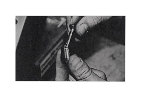
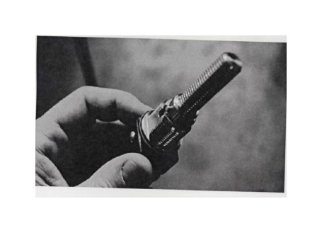
49. Locate the T-Latch lock assembly and observe the threaded barrel. The two flats of the threaded barrel will engage into the similarly shaped laser-cut lock hole in the tire carrier swing.
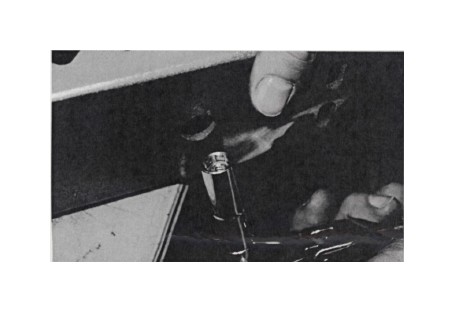
50. Fit the T-latch lock assembly and lock plate onto the tire carrier swing.
51. With the lock receiver and heavy duty T-latch in place, install the large washer lock-plate and large lock nut onto the large threaded barrel of the T-latch, on the back side of the tire carrier plate. FIRMLY tighten this nut, taking care not to strip it (either the threads or the wrench flats). Leave the lock nut with one of the flats lined up with the two tabs on the lock plate. Use a flat screwdriver to bend the two tabs upward, until flat against the adjacent flat surface of the lock nut, to lock it into place (the tabs are not shown bent into place in the following photos).
52. Install the remaining small washer lock plates, lock nuts, star lock-washers and Locking U-Plate onto the threaded shaft of the heavy duty T-latch, in the order shown in the following photo.
53. Run the inner lock-nut all the way inward, just to have it out of the way. Then thread the outer lock-nut inward a couple of turns, then close the tire carrier and test the latch to see that it turns and engages the U-plate firmly against the inside of the latch plate. If the T-latch won't turn 90-degrees, the U-Plate is too far inward and the lock-nut will need to be threaded outward. If the T-Latch does turn 90-degrees but the U-Plate is not tight against the back side of the latch plate, adjust it inward by threading the outer lock-nut inward. It may take several rounds of adjustments before it is just right. When properly adjusted, the U-Plate will engage firmly against the back side of the Latch Plate, seating the tire carrier firmly against the small rubber bumpers on the latch plate. Check to ensure that the tire carrier assembly doesn't rattle in the latch.
54. Once the position of the U-plate is properly adjusted, tighten the inner lock-nut and washers against the U-Plate. Hold the outer lock-nut and/or U-Plate with a wrench to ensure they don't move while tightening the inner lock-nut. Once the lock-nuts are firmly tightened, test the T-latch one more time to ensure it is still properly adjusted. Make sure both lock-nuts are turned so that the wrench flats on the nuts align with the lock-tabs on the washer lock plates.
55. Once all hardware is tight and properly adjusted, use a screwdriver to bend the lock-tabs on the lock washers outward, against the flats of the nuts, to lock them in place.
IMPORTANT' the position of the latch bar is critical! If it is too loose, it won't hold the tire carrier firmly closed. If it is too tight, it won't operate smoothly and risks damage to the latch. Remember, the entire load of the spare tire and carrier are not riding on this latch--it is merely acting to keep the carrier from swinging open. Other features of the tire carrier bear the weight and do the heavy lifting. Note that the position of the latch bar may need to be re-adjusted over time, as the assembly and the small rubber bump stops settle during use.
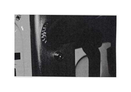
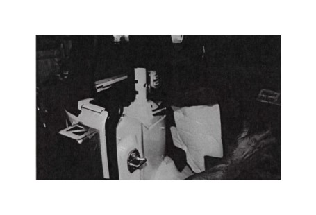
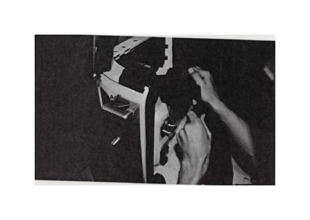
56. Open the tailgate and remove the plastic and carpet coverings to reveal the sheet metal on the top surface of the driver's side wheel housing/corner housing (near where the roll bar connects). To do so, you may need to remove some tie-down loops as shown in the photo.
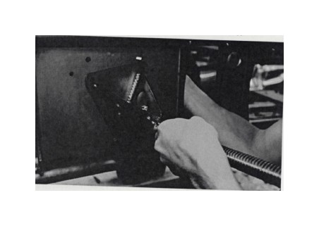
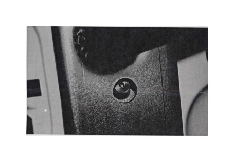
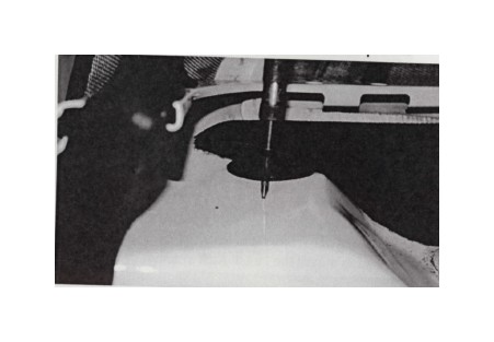
57. Peak through the taillight hole and observe the Upper Internal Brace that was partially installed in a previous step, and that there are three bolt holes in the brace, in a triangle arrangement. Holes will need to be drilled in the Jeep's body sheet metal in order to install bolts into these three locations. To do so, first an indent must be made at each hole location, that is visible on the other (top) side of the sheet metal. The best tool for this would be a 1/4" transfer punch and small hammer, in order to ensure the mark is perfectly centered. However an auto-punch or center punch and hammer will also work. Punch the sheet metal from below, by reaching through the taillight hole and using your punch tool of choice centered on the three hole locations.
If using an auto punch, several punches may be needed in order to make the dimples visible on the other (top) side.
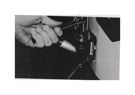
58. Re-use the punch from the TOP side on each of the hole locations, to invert the punch marks in order to center the drill so the holes can be drilled from the top side.
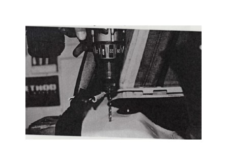
59. Drill the three hole locations beginning with a 1/8" pilot hole and finishing with a 1 /4" bit
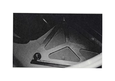
60. Install the Upper Internal Brace Clamp Plate (small triangle-shaped steel plate with three holes) as shown in the photo below, using (3) 1/4-20 X 1 Button Head Cap Screws SS 5/32" hex key), with Flat Washers and Lock Nuts (7/16" wrench), to clamp the body sheet metal firmly between the Clap Plate and the Upper Internal Brace.
61. Replace plastic covers, carpets etc. in the Jeep's interior.
62. Re-Install the driver's side taillight housing, remembering to plug the taillight pigtail back into the Jeep's wiring harness.
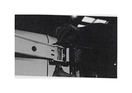
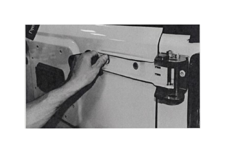
63. Re-install the OE plastic upper and lower hinge covers. With the tire carrier swung open all the way, open the tailgate slowly until it becomes apparent where the plastic hinge covers will need to be trimmed to allow clearance for the Hinge Brackets.
Use a silver or other light colored fine tip felt marker, or a scribe, to mark the material that will need to be trimmed for clearance.
64. Use a cutting tool of your choice to trim the plastic hinge cover.
65. Re-install the hinge cover and check for clearance. Trim further as needed.
66. If installing the vehicle's license plate on to the Tire Carrier, use the provided (4) 1/4-20 X 3/4 Stainless Steel Button Head Cap Screws, (4) 1/4" Stainless Steel Flat Washers and (4) 1/4-20 Stainless Steel Nylon Insert Lock Nuts to attach the license plate to the center plate of the Tire Carrier, using the four holes provided. Note that in some areas vehicle laws require the license plate to be illuminated at night. Poison Spyder sells an LED License Plate & 3rd Brake Light with 6' Extension Harness (p/n 41-04-LP6, sold separately) which may be installed along with the license plate.
67. If installing Roto-PaxTM fuel or storage packs, provisions are in place to bolt the Roto-Pax Pack Mounts directly to the Tire Carrier. The Tire Carrier is designed to accommodate two 2-Gallon Fluid Packs or Storage Packs (or one of each) on the rear surface, at either side of the license plate. Smaller 1-Gallon Fluid Packs may be mounted on either side. Note that mounting a 1-Gallon Pack on the driver's side will make it a little more difficult (though not impossible) to operate the T-Lock handle.
68. A Hi-Lift Jack may be installed on the passenger side instead of a 1-Gallon Roto-Pax (bolt holes are included for both) or horizontally above the license plate and rear Roto-Pax mounts. Square mounting holes are included in both locations for using 1/2-13 X 3" carriage bolts, nuts and urethane bushings. A hardware kit is available from Poison Spyder (sold separately) which includes everything needed to mount the Hi-Lift Jack in either of these locations.
At this point, the pre-installation of the JK Body Mounted Tire Carrier is Complete. Once everything has been tested for proper operation, all of the un-painted bare steel components must be un-installed and painted or powder coated. Once painted or power-coated, re-install using the same procedures outlined above. Consider the following pointers when painting or powder coating:
• When painting or powder-coating, mask off the interior of the bushing sleeves on the passenger side of the Tire Carrier Main Structure.
• The Acme threads on the Threaded Tire Mount may be powder coated in a thin, durable coating. There is enough clearance between the Wing Nut and the threaded rod to accommodate this, but not enough for a thick coat. Also, less-durable paint on the threaded rod may not hold up with the Wing Nut passing back and forth over it.
• Paint and powder coat may not hold up on the inner surface of the alignment holes where they contact the Alignment Cones. It may be better to leave that surface bare and keep it coated with a thin coat of grease to inhibit rust.
• While the Tire Carrier components are removed for paint, use the opportunity to apply touch-up paint to the edges of all holes drilled into the Jeep's sheet metal to help prevent corrosion.
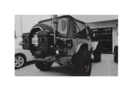
Congratulations, you have completed installation of your JK Body Mounted Tire Carrier!
CARE & MAINTENANCE
Check and re-tighten any fasteners that need it after the first day's use or 100 miles. This is especially important for the fasteners that hold the latch plate to the driver's side corner panel, the hinge bushing bolts, proper alignment of the alignment pins (adjusted using the adjustment cams on the top hinge bushing), and of course the T-handle latch mechanism. Check them again after a few weeks of use or 500 miles, then as part of your normal vehicle maintenance plan after that.

