 FREE 1 to 3-Day Delivery on Orders $149+ Details

How to Install Lite Spot Chassis Rock Lights Kit on your Wrangler
Installation Time
2 hours
Tools Required
- Wire cutters/strippers
- High temperature heat gun
- Drill and ¼” nut driver (if permanent mounting LiteSPOTs pods)
- Optional (electrical tape or shrink tubing)

Shop Parts in this Guide
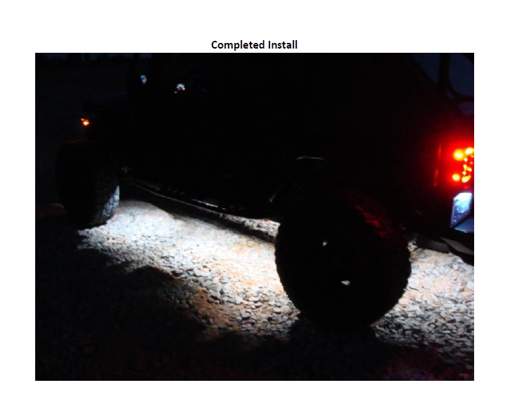
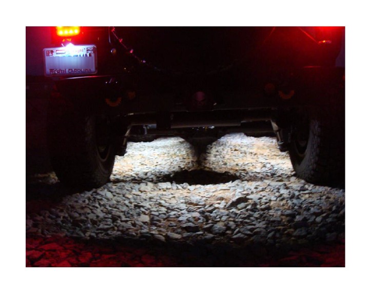
Pre-Installation Notes - Use the integrated magnets on the LiteSPOTs to determine the best setup for your vehicle prior to hard mounting them using the self-tapping screws. The setup used for the vehicle used for this installation guide (2014 Jeep JK Unlimited) used three LiteSPOTs pods on each side of the vehicle, one pod at the front, and one pod at the rear, for a total of 8 pods.
You may also consider using only the integrated magnets to mounts the pods to allow the ability to adjust the setup at a later time. For this install only the front and rear pods were secured with self-tapping screws, and the for the rest of the pods only the magnets were used and the extra wire was secured using zip ties so that the lights can be easily repositioned to use as temporary work lighting for repairs.
Installation Instructions:
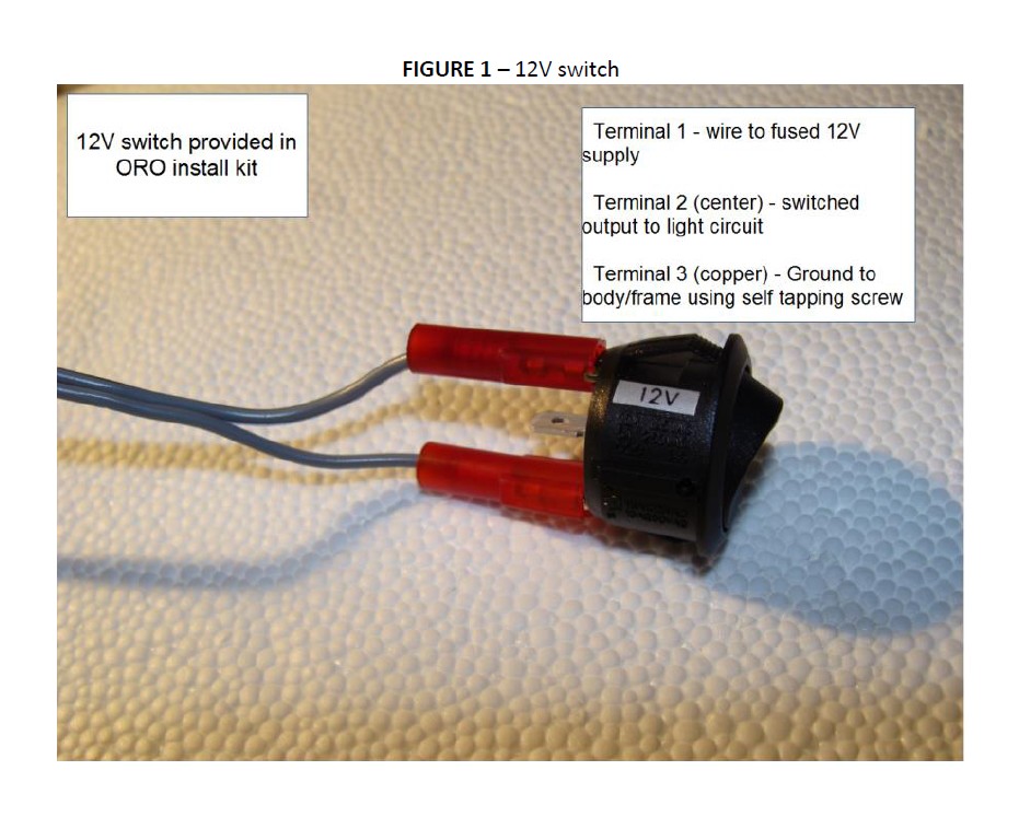
1. Choose location for the switch provided in the kit. (Figure 1) (Optional – use of sPOD or similar switch unit)
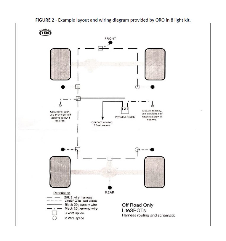
2. Choose layout for LiteSPOTs pods. Use integrated magnets to place in preferred locations, but do not permanently mount until all wiring is completed and tested. This will allow you to make adjustments with the pods for best results. An example layout and wiring diagram is included by ORO in the kit (Figure 2).
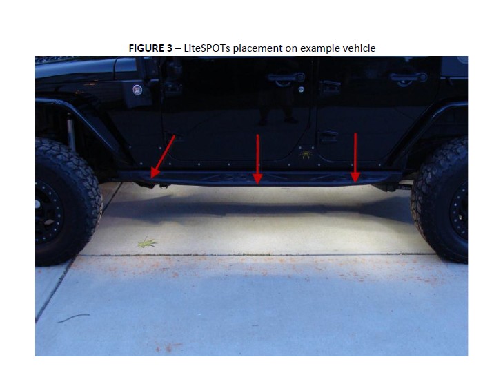
a. For this example we used three LiteSPOTs pods for each side of the vehicle and one each for the front and rear. The three side locations were evenly spaced for best coverage and the front LiteSPOTs was placed at a slight angle to provide better illumination of the front tire area. (Figure 3)
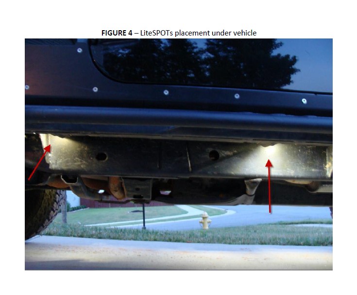
b. The LiteSPOTs were attached to the underside of the vehicle between the frame and the outside edge of the vehicle so that the underside was illuminated, but the LiteSPOTs pods were not visible. (Figure 4)
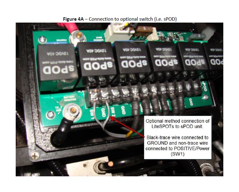
3. NOTE: If you are connecting the LiteSPOTs kit to an existing switch such as a sPOD (Figure 4A) you will not use the switch and flat spade connectors included in the installation kit, and you will not need to complete any additional ground connections to the body as the sPOD will provide power, ground, and a fuse for the wiring harness. Simply run the 25 foot wiring harness in series to each LiteSPOTs pod, connecting the positive wire for each pod (non-trace) to the harness positive wire (non-trace), and the ground wire for each pod (black-trace) to the harness ground wire (black-trace) to complete the installation.
4. Hard Wiring to battery - Begin wiring using the wire provided in the kit. Do NOT connect to the battery at this time to prevent injury and/or damage. Be sure to leave enough wire to connect to the positive and negative battery terminals at the completion of the wiring process. (If not wiring through the fuse block it is recommended that you use an inline fuse between the switch and the POSITIVE terminal of the battery).
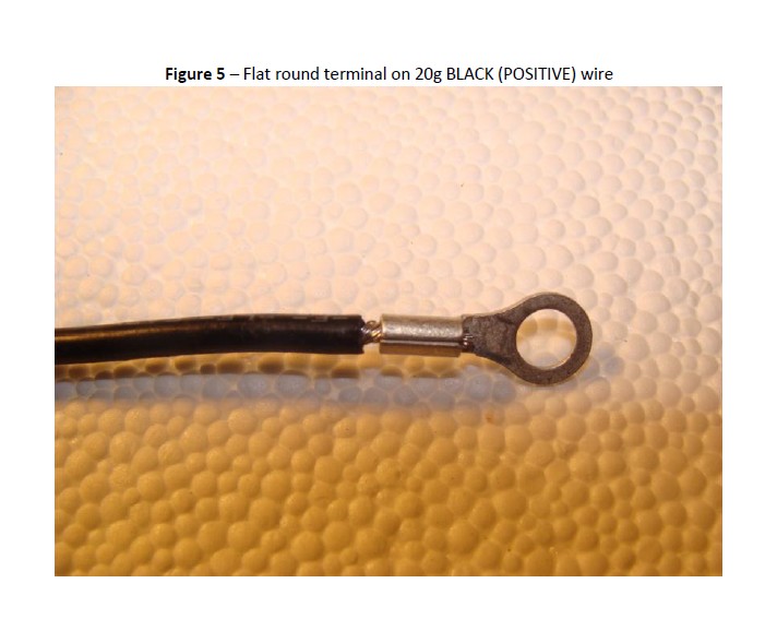
a. Using the provided BLACK 20g wire to attach the flat round terminal (provided in kit) to one end of the BLACK 20g wire (Figure 5).
a. Determine how much wire is needed between the switch location and battery and cut off any extra BLACK 20g wire. Save the remaining BLACK 20g wire for the remaining steps.
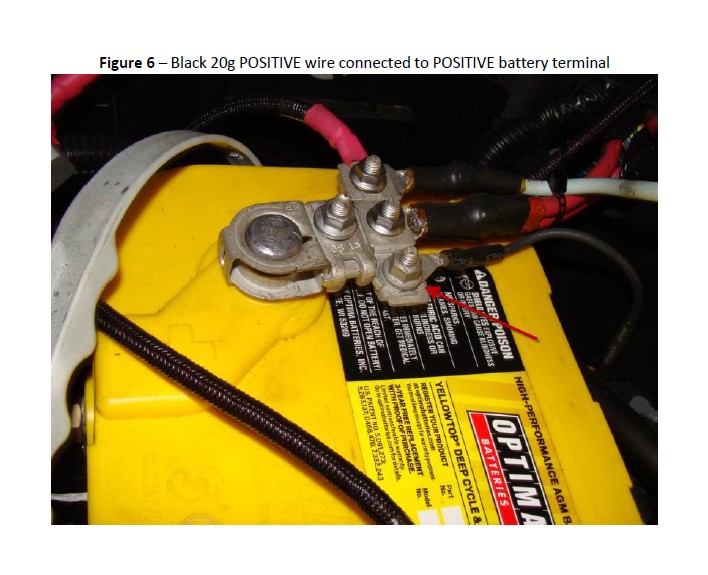
b. Upon completion of all wiring the other end of the BLACK 20g POSITIVE wire will be connected to the POSITIVE battery terminal of the vehicle (Figure 6)
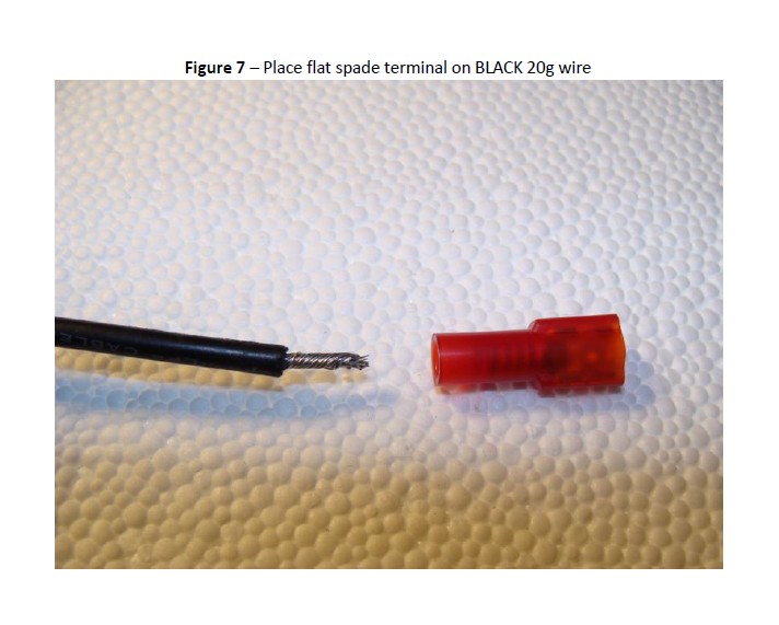
c. Place a flat spade terminal (included in kit) on the other end of the BLACK 20g POSITIVE wire. (Figure 7)
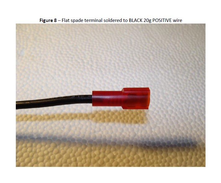
d. Use a high temperature heat gun to melt the solder (silver) in the flat spade terminal and to shrink the tubing at the same time connecting the wires and creating a sealed connection. (Figure 8)
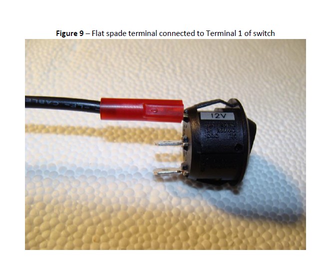
e. Connect the flat spade terminal of the BLACK 20g POSITIVE wire to Terminal 1 (12V label) of the switch. (Figure 9).
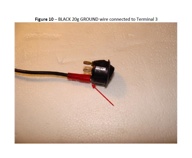
f. Using the same process previously detailed, attach a flat spade terminal to one end of the extra unused BLACK 20g wire. Use the flat spade connector to attach the wire to Terminal 3 of the switch. Terminal 3 is the copper colored terminal on the switch. (Figure 10)
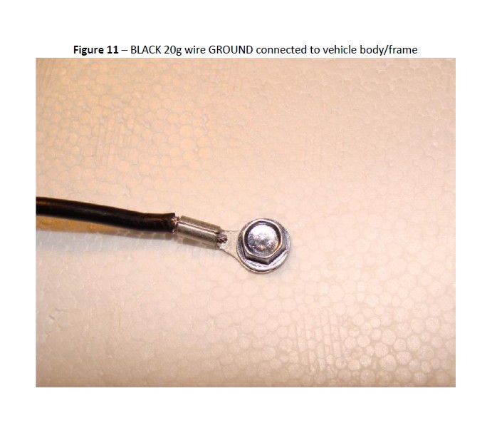
g. Connect the other end of that wire to the body of the vehicle using a self-tapping screw to GROUND the switch. (Figure 11)
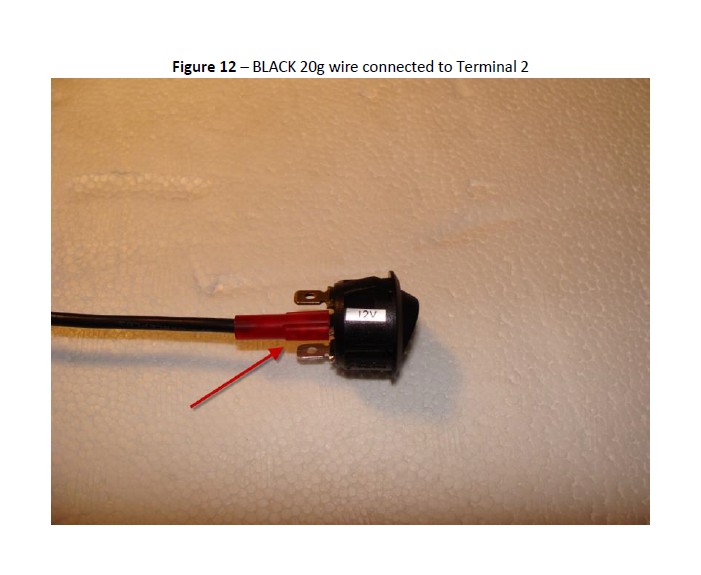
h. A third section of BLACK 20g wire will be used to connect the switch to the wiring harness that connects all of the LiteSPOTs pods. Connect a flat spade terminal to one end of the wire and attach it to Terminal 2 of the switch. Terminal 2 is the center terminal of the switch. (Figure 12)
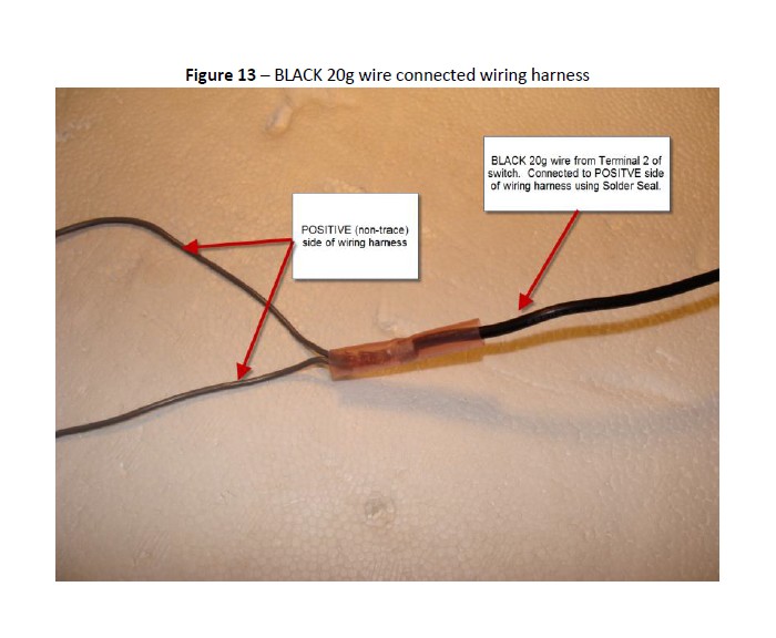
1. The other end of this wire will connect wiring harness, which is the 25 foot 2 conductor wire included in the installation kit.
2. One side of the harness has a black trace on it and contains silver wire – this is the GROUND side of the harness. The other side of the harness does not have a black trace on it and contains copper wire – this is the POSITIVE side of the harness.
3. Connect the BLACK 20g wire from Terminal 2 to the POSITIVE (non-trace) side of the wire harness using one of the Solder Seals included in the installation kit. (Figure 13)
i. Attach the GROUND wire of the harness to the body using a self-tapping screw. This can be completed at the end of the wiring harness, or can be spliced into the middle of the wiring harness using a Solder Seal.
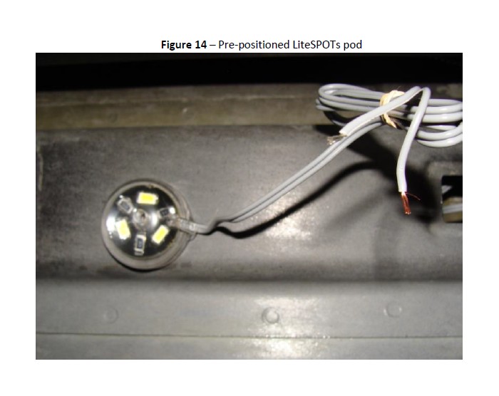
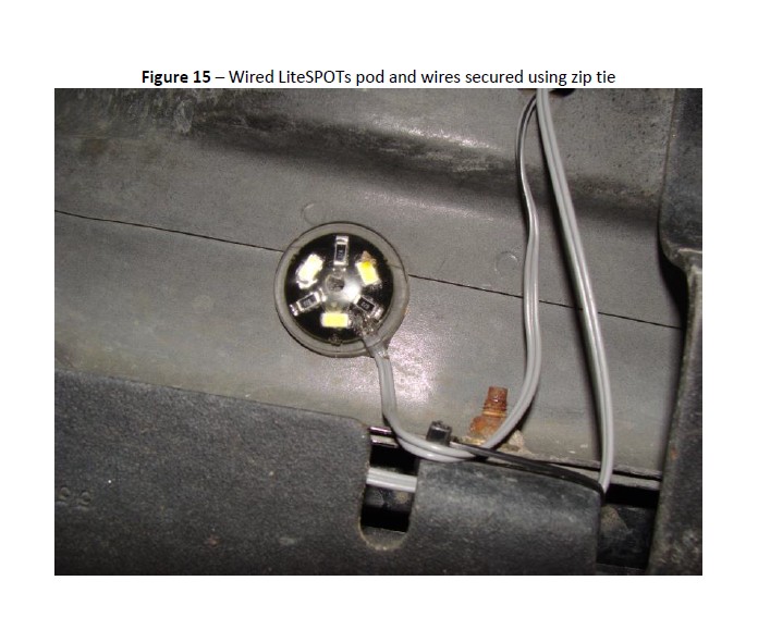
5. Run the wiring harness to each of the pre-positioned LiteSPOTs pods (Figure 14) and use two Solder Seals to connect the pod to the wiring harness. Connect the positive wire for each pod (non-trace) to the harness positive wire (non-trace), and the ground wire for each pod (black-trace) to the harness ground wire (black-trace). Use included zip ties to secure loose wires (Figure 15).
6. Once all LiteSPOTs pods have been connected to the wiring harness connect the harness to the battery/power source.
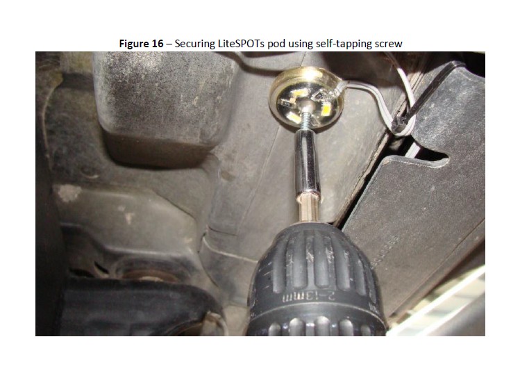
7. Turn on switch to test lights and make any needed adjustments to achieve desired results. If you choose to mount the pods permanently, use a drill with a ¼” nut driver and the included self-tapping screws through the pre-drilled hole in the pod to secure the pod to the vehicle (Figure 16).
8. Use zip ties to secure any loose wiring. Conceal wires inside existing wire harness covers under the vehicle for a finished appearance.
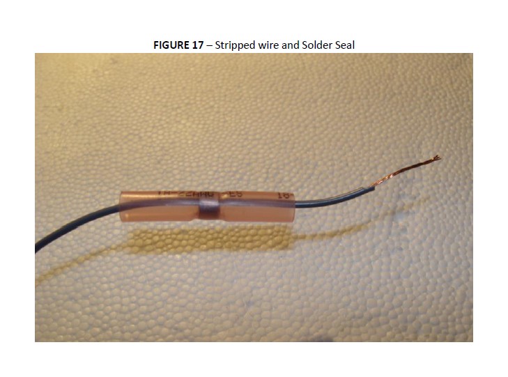
To connect wires using a Solder Seal –
1. Separate the harness wires from each other for about 2 inches.
2. Strip about 3/4 of an inch of insulation from the ends of the wires being connected.
3. Slide a Solder Seal onto one of the wires so that the bare end of the wire is exposed (Figure 17)

4. Twist the ends of the wires together and then slide the Solder Seal over the connection until the solder (silver) part of the Solder Seal covers the wires to be connected. (Figure 18)
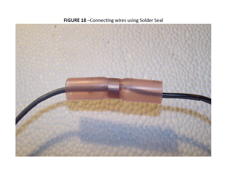
5. Use a high temperature heat gun to melt the solder (silver) in the Solder Seal and to shrink the tubing at the same time connecting the wires and creating a sealed connection.
OPTIONAL – use electrical tape or additional shrink tubing to create a water-proof seal over all connections.
Installation Instructions Written by Extreme Terrain Customer D. Barton 05/21/2015
