 FREE 1 to 3-Day Delivery on Orders $149+ Details

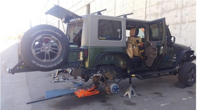
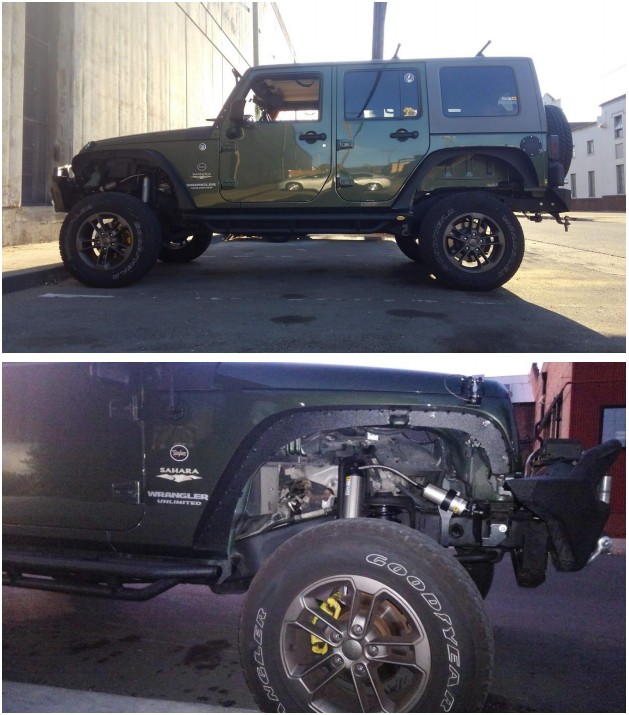
How to Install Old Man Emu 4 in. Suspension Lift Kit w/ BP-51 High Performance Bypass Shocks (07-18 Jeep Wrangler JK) on your Jeep Wrangler
Installation Time
6 hours
Tools Required
- Sockets and Open ended wrench sets -Metric and Imperial
- Torque Wrench
- Vice Grips
- Scribe
- File
- Allen Key set
- Jack Stands and a floor jack (2 floor jacks are helpful)
- Die Grinder Safety Glasses and ear plugs
- Tape measure
- PB Blaster for old models
Note: When fitting larger diameter tires it is necessary to fit aftermarket wheels (rims) with greater offset (reduced backspacing) to clear sway bar, sway bar links and control arms. Note: For 2012 models with 3.6L engine, modifications to exhaust or driveshaft are required to avoid contact of the driveshaft and exhaust when the suspension is at full droop.
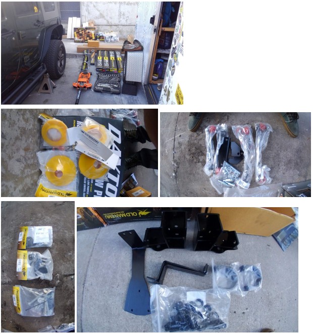
Before starting the installation, ensure all parts listed are in the box.
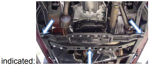
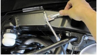
AUTO TRANSMISSION- Remove transmission Cross-member by removing three bolts
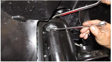
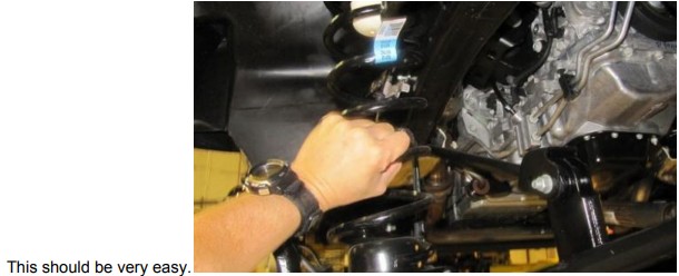
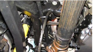
1: While at ride height, remove the top shock absorber mounting nut, washers and bushings using a 16mm wrench.
2: Remove track bar while at ride height.
3: Lift vehicle and support with jack stands so you have enough room to droop the front axle.
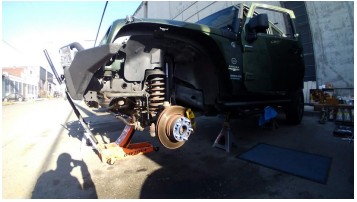
4: Remove front wheels and drop axle down a couple of inches after the frame rests on the stands. This will give you more room to avoid head bonking.
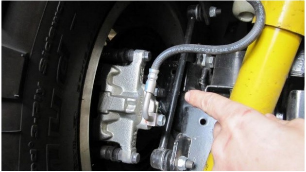
5: Remove front brake line bracket using a 10 mm wrench or socket.
6: Remove front sway bar end links on both sides of the front sway bar.
7: Remove front shock absorber lower mounting bolts and front shock absorbers.
8: Lower the axle far enough to pull out old coil springs, but watch for brake lines and sensor wires to prevent breaking when lowering the axle. When its low enough, remove the springs.
TO INSTALL OPTIONAL CASTOR AND DRIVELINE CORRECTION KIT TO HELP CORRECT CASTOR ANGLES:
1: DIsconnect lower control arms at axle end and loosen them at chassis. Hang them out of the way.
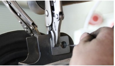
2: Using vice grips clamp the driveline alignment plates to the axle mount, placing the plates as shown. Ensure the alignment plate is mounted with the pilot hole towards the rear of the vehicle
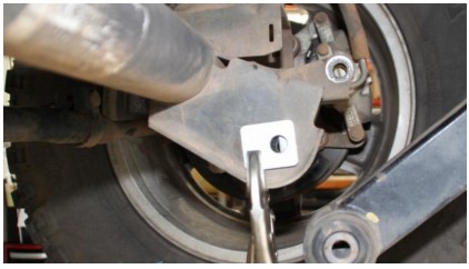
3: Mark the new 14mm hole position very carefully with the knowledge that too much room leaves too much room for your suspension to move around.
4: Remove the plates and use a die grinder to carefully grind out the metal and file any burred edges.
5: Reposition alignment plates and reconnect the lower control arms using the hardware supplied. Do Not torque at this stage.
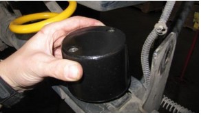
9:Fit the front Bump Stop spacers as per the directions that come with the bump stop kit.
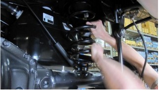
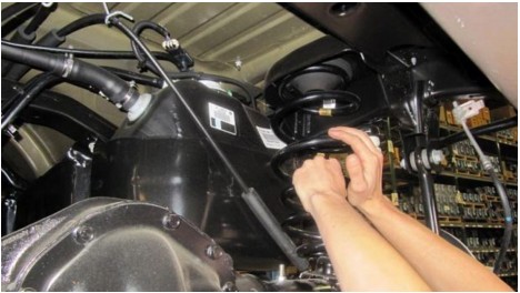
10: Once bump stops are installed, install the new Old Man Emu Front Springs!
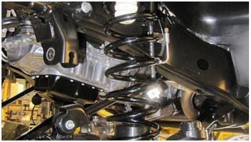
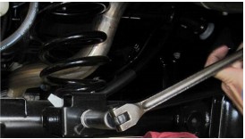
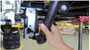
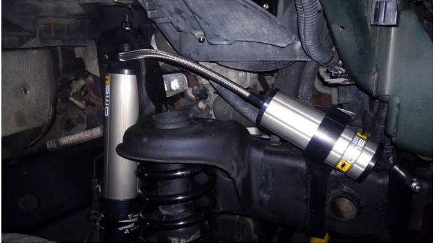
11: Fit the new BP-51 Shock Absorbers as per the instructions that come in the box. First mount the top of the shock, then raise the axles back up pinching the springs into position and lining the lower shock absorber holes up with the spots on the axle to mount them to.
Auto transmission models only: Refit transmission cross member with spacers and new bolts provided in FK49 kit.
12: For all models other than Rubicon, a sway bar disconnect system is provided in the kit.
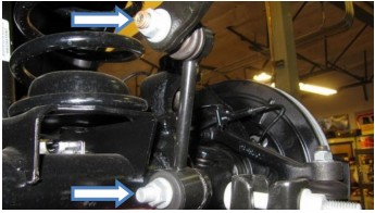
Assemble the non greasable pin to the bracket as shown. For Rubicon models simply connect the new sway bar links using the metal sleeve provided in the sway bar kit.
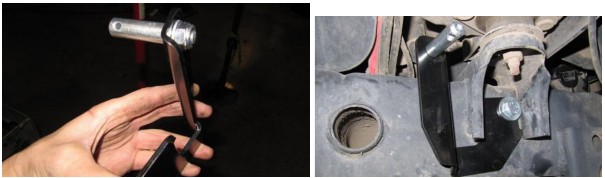
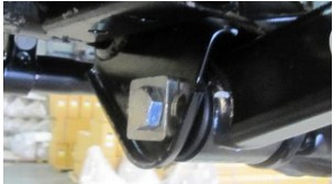
13: Fit the sway bar disconnect park brackets to the chassis rails. This may require a hole to be drilled on some models.
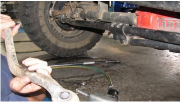
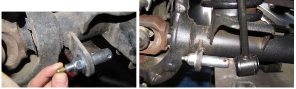
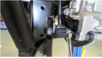
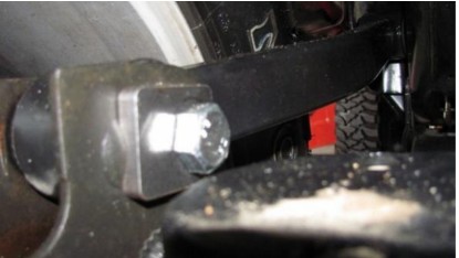
14: Fit greasable sway bar link pin and nut to axle bracket. Fit the grease nipple and tighten with spanner. Hold flat section on pin with 17mm open end spanner to prevent pin from spinning when tightening.
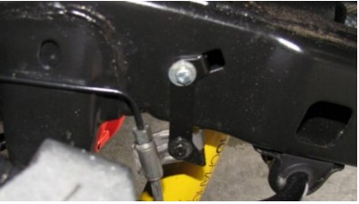
15: Fit brake line drop brackets using the fasteners provided
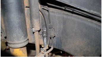
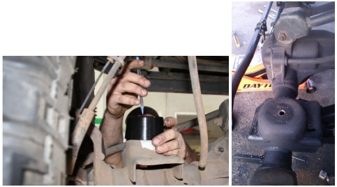
16: Make sure your front differential breather tube is relocated allowing t=for increased wheel travel. Use included zip tie.
17: Fit FK 50 Steering Stabilizer kit using instructions in the box. There is information regarding weather or not you need the bracket included for extra height and strength. I added it because it looks stronger.
18:Lower vehicle to new GROUND HEIGHT!!!
Fit new OME adjustable track bar to the vehicle using original bolts. Adjust track bar until the front axle is correctly centered relative to the chassis rails at ride height. Once adjusted, secure with thread locker and tighten lock nut.
19: Once axle is centered, adjust drag link to re-centre the steering.
20: Torque all bolts to spec!
Shock absorber upper nut 20 ft-lb
Shock absorber lower nut- 56 ft-lb
Suspension arm lower axle bracket nut- 125 ft-lb
Suspension arm lower frame bracket nut- 125 ft-lb
Suspension arm upper axle bracket nut/ bolt- 75 ft-lb
Suspension arm upper frame bracket bolt- 75 ft -lb
Stabilizer Bar link upper nut - 75 ft-lb
Track bar frame bracket nut- 125 ft -lb
Track bar axle bracket bolt- 125 ft-lb
REAR:
1: Lift the rear of the vehicle and put on jack stands; Remove rear wheels.
2: Disconnect brake line brackets on both sides.
3: Remove rear sway bar links on both sides.
4:Disconnect rear track bar at the axle end and loosen chassis end
5: Remove rear shock absorbers.
6: Lower axle and remove rear springs.
TO INSTALL OPTIONAL CASTOR AND DRIVELINE CORRECTION KIT TO HELP CORRECT CASTOR ANGLES:
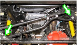
1:Disconnect the rear upper control arms at the axle end and loosen at chassis end. Move control arms up and clear of the axle mounts.
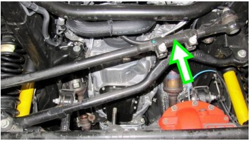
2: Using vice grips clamp the drive line alignment plates to the axle mount, placing the plates as shown. Ensure the alignment plate is mounted with the pilot hole towards the front of the vehicle.
Caution: Take care when completing the following steps as incorrect fitment may result in excessive suspension movement!
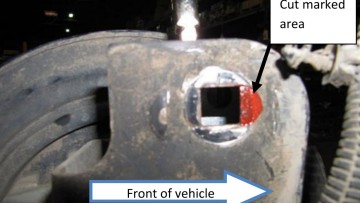
3: Using a scribe, mark the new 14 mm hole position.
4:Using a die grinder, cut the marked area.
5: With alignment plates in position, reconnect upper control arms using the new M14x100mm flange bolts and cone lock nuts provided.
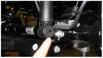
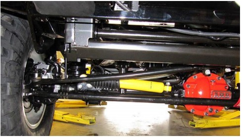
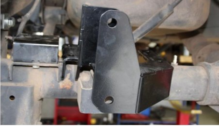
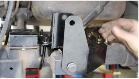
7:Fit the new rear track bar bracket to the rear axle as shown.
Re-fit the original bolt and nut back in their original positions with the new spacer tube fitted in the original track bar position.
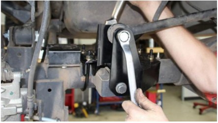
8: Clamp the track bar bracket in position with the 2 U-bolts provided. Torque u-bolts to 44Nm/33ftlb Torque Original bolt to 150Nm/110ftlb
9: Fit the track bar to the new bracket using new bolt and nyloc nut and flat washers provided.
10: Fit the rear bump stops using the fitting instructions provided in the kit
11: With bump stops installed, install new OME rear springs.
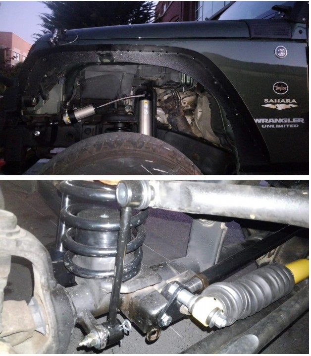
12: Install BP-51 shock absorbers as per fitment instructions included.
13:Fit the brake line drop brackets provided as shown.
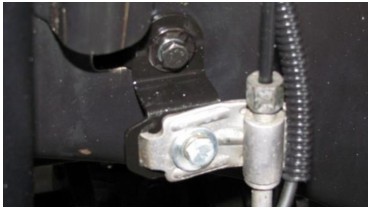
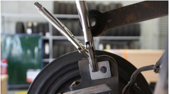
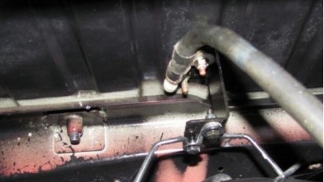
14: Fit the hand brake relocation bracket as shown.
15: Fit OME sway bar links as shown.
16: Re-fit wheels and lower to ride height.
Align wheels at a professional alignment shop.
Torque to spec before driving.
Shock absorber upper bolts- 37 ft-lb
Shock absorber lower nut 56 ft-lb
Suspension arm lower axle bracket nut- 125 ft-lb
Suspension arm lower frame bracket bolt- 125 ft-lb
Suspension arm upper axle bracket bolt- 125 ft-lb
Suspension arm upper frame bracket bolt- 125 ft-lb
Stabilizer bar to link nut/ bolt- 75 ft-lb
Track bar frame bracket nut- 125 ft-lb
Track bar axle bracket nut- 125 ft-lb
