 FREE 1 to 3-Day Delivery on Orders $149+ Details

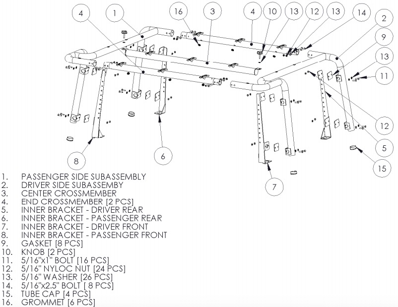
How to Install a MBRP Black Coated Roof Rack System on your 2007-2010 Jeep Wrangler JK 2 Door
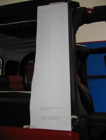
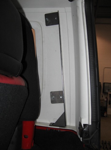
1. Mark the holes to be drilled in the factory hardtop using the supplied Hole Templates. There is a front and rear template. LH and RH are mirror image of each other and will use the same template. Trim the template and tape it to the outside of the Hardtop. ENSURE THAT THE TEMPLATES ARE ALINED WITH THE HARDTOP AS DESCRIBED. THE REAR TEMPLATE MUST BE ALIGNED WITH THE BOTTOM EDGE OF THE HARDTOP, AND THE REAR VERTICAL ‘SEAM’ OF THE HARDTOP. THE FRONT TEMPLATE MUST BE ALIGNED WITH THE BOTTOM EDGE OF THE HARDTOP AND THE VERTICAL DOORJAM EDGE OF THE HARDTOP. THE WINDOW PROFILES ARE USED AS A REFERENCE ONLY AND SHOULD NOT BE USED TO POSITION THE TEMPLATE OVER THE PROCEDURE OUTLINED ABOVE. Once the Hole Templates are properly positioned, use a 1/16” bit to drill a pilot hole through the template and through the Hardtop. Transfer the Hole Templates to the other side and repeat. Once all pilot holes are drilled, remove the templates and drill the holes out with a 3/8” bit. Refer to Figures 1 and 2.
Figure 1
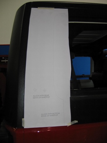
Figure 2
2. Remove the 4 corner factory hard top mounting bolts, leaving the center 2 in place. Loosely attach the Driver and Passenger side, Front and Rear Inner Brackets using the previously removed bolts. The brackets can easily be identified by the cut-out in the lower pad, ie DF, DR, PF, PR. The brackets may not exactly line up with the previously drilled holes. The brackets are flexible and can be moved to line up with the holes. This is normal. Refer to Figure 3.
Figure 3
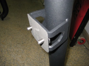
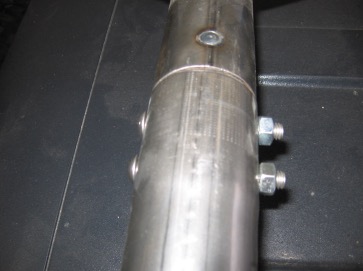
3. Install the Passenger Side Subassembly by first preassembling with the supplied 5/16”x1” Bolts. Be sure to place a 5/16” Washer under the head of the bolts. Next slide the supplied Gaskets over the threads of the bolts. The Gasket will help hold the bolts in place while installing the assembly. Refer to Figure 4.
Figure 4
Note: if you plan to run lights, now is the time to start routing the wiring through the tubing. Typical installations route the wiring harness through the forward downtube of one of the side subassemblies. There is a cutout on the front inner brackets for wiring to pass through. You will need to drill the downtubes to suit your needs.
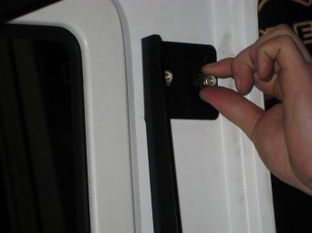
4. Lift the Passenger Side Subassembly into position on the side of the hardtop. Line up the holes and slide the 5/16”x1” Bolts through the hard top, through the holes in the Inner Brackets, and secure using the supplied 5/16” Nyloc Nuts. Do not fully tighten the bolts yet. You will need 2 people for this step. Refer to Figures 5 and 6.
Figure 5
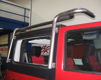
Figure 6
5. Before installing the End Crossmembers, insert the Grommets into the wiring holes. Install the End Crossmembers by sliding the ends of the Crossmembers into the ends of the Passenger Side Subassembly. Ensure the accessory mounting pads are facing up, the light wiring holes are facing rearward on the Front Crossmember, forward on the Rear Crossmember, and the bolt holes in the Crossmembers line up with the holes in the Passenger Side Subassembly. Secure the Crossmembers by inserting the supplied 5/16”x2.5” Bolts, 5/16” Nyloc Nuts and Washers. No washers are required under the heads of these bolts. Do not tighten yet. Refer to Figures 7 and 8.
Figure 7
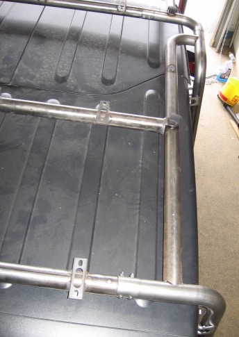
Figure 8
6. Preassemble the Driver Side Subassembly as shown in Step 3. Lift the assembly into position as before. Be sure to align the Crossmembers with the Driver Side Subassembly as well. Some adjustment may be required to get everything to line up and slide into position, this is why all fasteners should be left loose. Secure the Driver Side Subassembly to the hardtop using the supplied 5/16”x1” Bolts, 5/16” Nyloc Nuts and Washers. Secure the Crossmembers to the Driver Side Subassembly with the supplied 5/16”x2.5” Bolts, 5/16” Nyloc Nuts and Washers as in Step 5. 2 people will be required for this step as well.
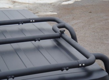
7. Install the Center Crossmember by choosing a location and securing with the supplied Knobs and 5/16” Washers.. Refer to Figure 9.
Figure 9
8. Tighten all fasteners to no more than 12 ftlbs. Be careful to not over tighten. Damage to the finish and/or components may result.
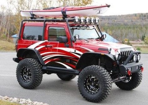
* Shown with optional Light Bar Kit #130987
Congratulations! You are finished. We are sure that you will enjoy this Off Camber Fabrications product by MBRP Inc MBRP Inc.
