 FREE 1 to 3-Day Delivery on Orders $149+ Details

How to Install a MBRP Bumper Light Bar/Grill Guard on your 2007-2017 Jeep Wrangler JK
Tools Required
- Spring Compressor
- Silicone spray
- Drill assortment
- Hammer
- Combination
- wrenches
- Floor jacks
- Wheel chocks
- 1/2” drill motor
- T55 torx bit
- 11/32” Drill bit
- 17/32” Drill bit
- Torque wrench
- 1/2 drive ratchet and sockets
- Allen wrenches
- Large “C” clamps and /or bench vise
- Heavy duty jack stands
- Safety glasses
- Anti-seize compound

Shop Parts in this Guide
FRONT INSTALLATION
1. Place the vehicle on a level surface. The vehicle will need to be placed on jack stands front and rear to install the long arm kit.
2. Remove the front tires and wheels.
3. From inside the engine compartment, remove the upper stud nut, retainer and grommet from both of the front shocks using a 15mm socket.
4. Remove both of the front sway bar end links using a 15mm wrench for the upper and a 18mm wrench for the lower. Retain lower link hardware for re-use.
5. Place a floor jack underneath the axle for support and complete the removal of the front shock absorbers from the lower mount using a 13mm Socket. Retain the stock lower hardware for reuse.
6. Do not reuse the original factory shocks.
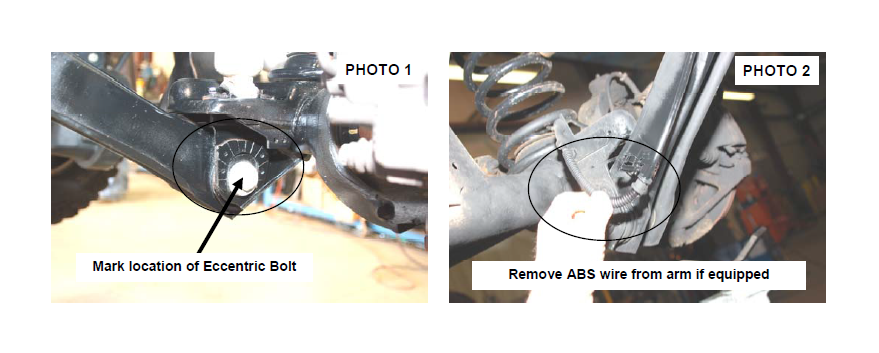
7. If your axle is equipped, mark the position of the lower control arm cam bolt and axle brackets for installation reference. See Photo 1. If equipped with ABS brakes, remove the sensor wires and clamps for the inside of the lower arms and save clamps for re-use. See Photo 2.
8. Remove the track rod from the axle and from the frame using a 15mm (axle) & 18mm wrench (frame). Retain the axle hardware for reuse.
9. Remove the coil spring clip located on the bottom coil seat on the driver side of the vehicle using a 13mm socket. Retain the clip and hardware for reuse.
10.Remove the brake caliper from the axle using a 13mm socket and secure out of harms way.
11.Lower the axle and remove the coil spring. A coil spring or strut compressor may be needed to remove the stock coil spring.
12.Support the front axle and remove the stock lower control arm by removing the nut, cam, and cam bolt (if equipped) from the axle bracket and then removing the nut and bolt from the frame bracket doing one side at a time using a 21mm socket & wrench. Retain the stock hardware.
13.Remove the upper arm from the mount using a 15mm wrench. Do not retain stock hardware.
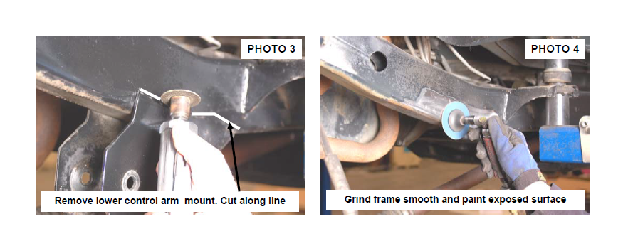
14.Cut the stock lower control arm mounts from the frame as shown in Photo 3 by cutting the weld that secures the bracket to the frame using a cutting wheel or similar cutting tool. Take care not to cut in to the frame rail.
15.After the bracket is removed, grind the surface smooth as shown in Photo 4 and paint the area to prevent rusting
16. On the rear of the vehicle, remove the stock shocks from the vehicle using a 13mm socket on the upper and a 18mm socket / wrench on the lower mount. Retain hardware for reuse.
17. Remove the rear track rod from the axle using a T55 Torx bit and a 15mm & 18mm wrench on the frame. Retain the hardware for reuse.
18. Lower the axle and remove the coil springs. Remove the rear sway bar links using a 15mm socket / wrench. Retain the upper hardware for reuse
19. Support the rear axle. Remove the brake line from the upper control arms using a 13mm wrench. Remove the lower control arms using a 21mm wrench & socket. Retain the factory axle hardware.
20. Remove the upper control arms from the rear axle using a 15mm socket / wrench. Retain axle hardware for reuse.
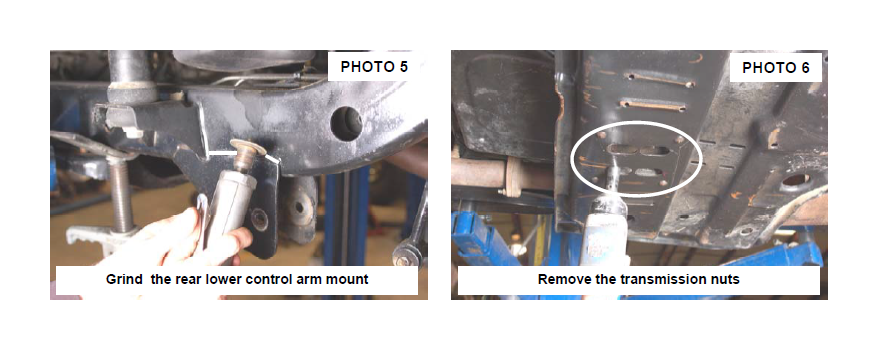
21. Cut the stock rear lower control arm mounts from the frame as shown in Photo 5 by cutting the welds that secures the bracket to the frame using a cutting wheel or similar cutting tool. Take care not to cut in to the frame rail. Paint the exposed surface to prevent rusting.
22. Remove the transmission nuts as shown in Photo 6 with a 13mm socket to allow the skid plate to be removed. Retain the factory hardware. On Rubicon models, remove the compressor bracket from the skid plate using a 13mm wrench. Retain the hardware for reuse. Removal of the compressor from the vehicle is recommended to ease in installation.
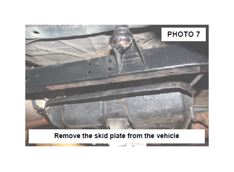
23. Support the factory skid plate and remove the 6 bolts (3each side) that secure it to the frame using a 3/4” socket. Retain the factory hardware. See Photo 7. If equipped with a forward skid plate (present on most auto transmission models) remove at this time using a 13mm & 3/4” wrench. This skid plate will not be reused. Lower the main skid plate and remove for trimming. Make sure stock lines are not pulled or overextended.
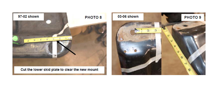
24. On 97-02 models , measure back 2 3/8” on the drivers side only rear corner of the skid plate and mark with tape. See Photo 8. Cut using a reciprocating saw. This is done to allow clearance for the new lower control arm mount. Grind the edges smooth. On 03-06 models measure back 2 3/4” from hole edge as shown on both sides of the skid plate and 6 1/2 from the sides and cut using a reciprocating saw. See Photo 9.
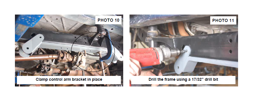
25. Align the holes in the frame with the new control arm bracket and install the factory skid plate bolts. Clamp in place using a large c-clamp. See Photo 10.
26. Using the new bracket as a guide, drill using a 17/32” drill bit through the inner and outer frame rail. See Photo 11. NOTE: The drill must be kept level for the frame holes to align with the new bracket. Note: Use caution when drilling the frame rail to avoid any lines on the inside of the frame rail, including fuel lines and brake lines.
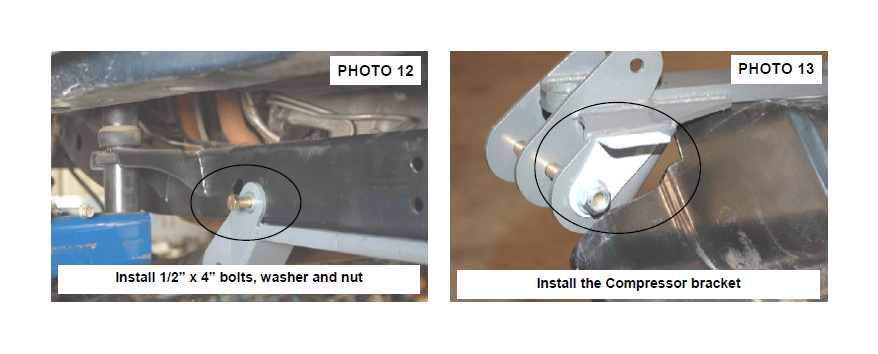
27. Install the supplied 1/2” x 4” bolts, washers and nuts as shown in Photo 12 through the frame rail and tighten using a 3/4”wrench. Repeat steps 29-31 for the opposite side.
28. On Rubicon Models, the compressor bracket will be installed on the rear lower control arm bolt as shown in Photo 13. Temporarily insert 9/16” x 7” bolt at this time and continue to next step.
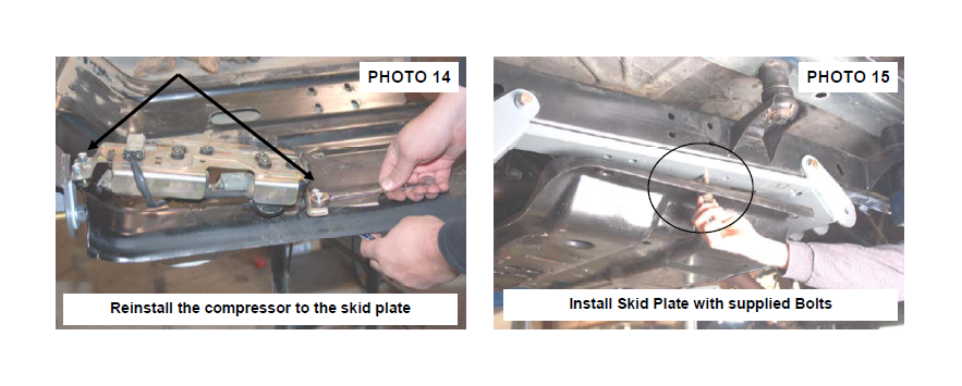
29. Using the stock compressor bracket as a guide, align the hole in the frame mount bracket and drill two holes using 11/32” drill bit and secure to the skid plate using the supplied 5/16” x 1” bolts, washer and nuts. The compressor will be secured to the new bracket with the supplied 5/16” x 1” bolts, washer and nuts. See Photo 14.
30. Reinstall the skid plate with the supplied 1/2” x 4 1/2” for 97-02 Models and 12mm x 65mm bolts & washers for 03 and up models. Tighten the 1/2” bolts using a 3/4” socket and the 12mm using a 19mm socket See Photo 15.
31. Locate the front lower control arm bushings and lubricate them with a lithium grease. Assemble the bushings and sleeves in the lower control arm. Adjust the arm to a length of 29 3/4” from center of bushing to center of bushing. Tighten jam nut using an adjustable wrench.
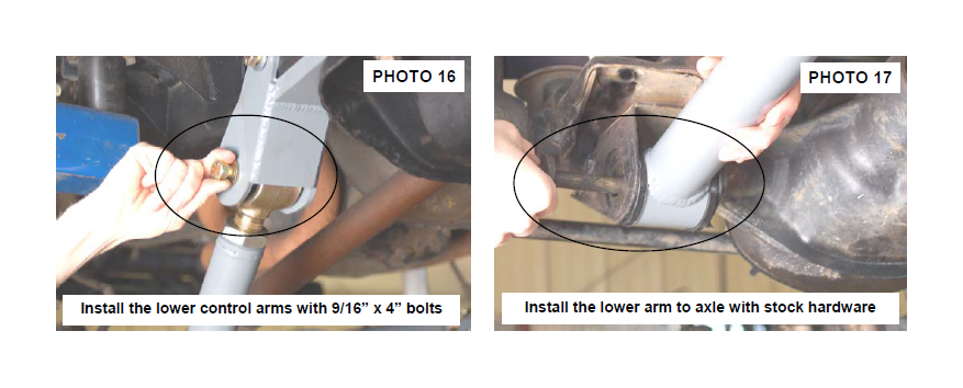
32. Install the new front lower control arm in the new mount with the supplied 9/16” x 4” bolts, washers / nuts making sure the joint is centered. Do not tighten at this time. See Photo 16.
33. Install the lower control arm on the axle with the factory hardware. See Photo 17. Do not tighten at this time
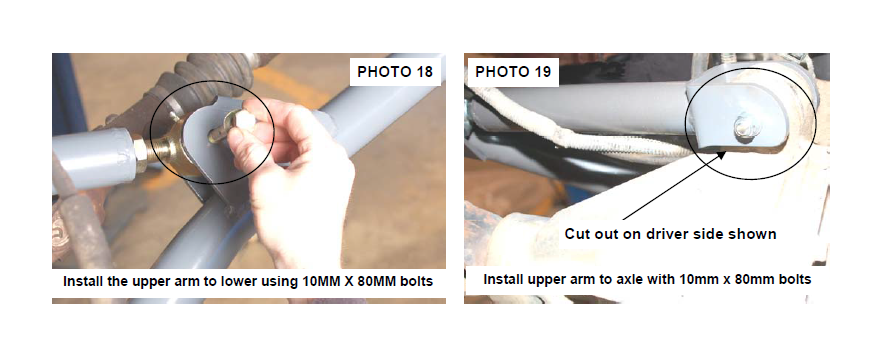
34. Assemble the front upper control arm and adjust to a length of 15 1/4” from center of hole to center of bushing. Install on the new lower control arm with the supplied 10mm x 80mm bolt, washers / nuts. See Photo 18. Do not tighten at this time. Tighten jam nut using an adjustable wrench.
35. Install the new upper arm to the axle using the supplied 10mm x 80mm bolt, washers & nuts. Do not tighten at this time. See Photo 19. If installing on a vehicle equipped with a Dana 44 front axle, be sure to install the arm on the drivers side with the cut out over the differential to allow clearance. See Photo 19.
36. Moving to the rear of the Jeep, Grease the supplied bushings with a lithium grease and install the bushings in the rear upper and lower control arms. Adjust the lower control arms to 27 3/4” and the upper control arms to 29” long. On LJ Jeeps: Adjust the lower arms to 38 3/4” and adjust the upper control arms to 39”.
37. Install the new rear lower & upper control arm in the new mount with the supplied 9/16” x 7” bolts. Washers / nuts making sure the lower arm joint is centered in the mount. Do not tighten at this time. See Photo 20. 38. If installing on a Rubicon Model, reinstall the compressor bracket on the bolt as shown in Step 28.
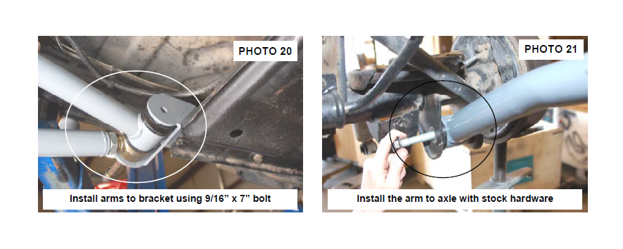
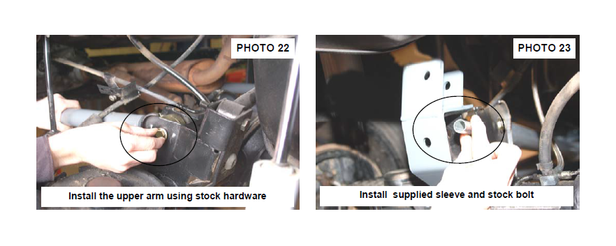
39.Install the upper arm on the axle using the stock hardware. Do not tighten at this time. See Photo 22.
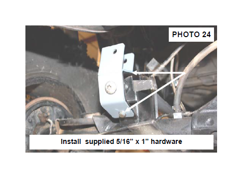
40.Locate the new track rod bracket and install on the rear axle mount as shown in Photo 23 with the supplied crush sleeve using the stock bolt and flag nut. Tighten using a T55 torque head bit.
41. Install the supplied 5/16” x 1” bolts, washers & nuts in the bracket as shown in Photo 24. Tighten using a 13mm wrench.
42. The track rod will be tightened on both ends after the vehicle has been lowered to the ground and is supporting it own weight. This is done to ensure the axle is centered under the body.
43. Install the coil springs making sure the rubber damper in positioned in the upper mount. It may be necessary to use a coil spring or strut compressor to install the new coil springs.
44. Install the wheels and tires and tighten the lug nuts to the factory specifications using crossing pattern (80- 110 ft. lbs).
45.Remove the jack stands and lower the vehicle to the ground.
46.On the front lower control arms; align the reference marks on the adjustment cams and lower arm axle brackets and tighten to 85 ft. lbs using a 21 socket & wrench. Tighten the upper using a 15mm socket & wrench. Repeat for the rear of the vehicle.
47. On the rear, make sure the body is centered over the axle. It is important to center the vehicle over the axle to ensure proper tracking and alignment.
POST INSTALLATION
1. Rotate driveshaft and check for interference at differential yoke and u-joint. If necessary, lightly dress casting(s) and/or U-joint tabs in order to eliminate binding.
2. Have a qualified alignment center realign front end to factory specs. As a general rule you set caster to the minimum of the factory spec and set toe-in to the maximum.
3. Install Warning to Driver decal on sun visor.
4. Adjust headlights to proper settings
5. Grease all control arms and periodically grease as required.
6. All components must be retightened after 500 miles, and every three thousand miles after installation.
7. The factory exhaust must be modified / rerouted to have adequate clearance on all fixed and moving components.
8. A CV type driveshaft and slip yoke is recommended for the 4” kit and a necessity for the 6” kit to avoid drive shaft
vibration.

